Simultaneous Vanishing Point Detection and Camera Calibration from Single Images Bo Li, Kun Peng, Xianghua Ying, and Hongbin Zha The Key Lab of Machine Perception (Ministry of Education), Peking University, Beijing P.R. China
Abstract. For images taken in man-made scenes, vanishing points and focal length of camera play important roles in scene understanding. In this paper, we present a novel method to quickly, accurately and simultaneously estimate three orthogonal vanishing points (TOVPs) and focal length from single images. Our method is based on the following important observations: If we establish a polar coordinate system on the image plane whose origin is at the image center, angle coordinates of vanishing points can be robustly estimated by seeking peaks in a histogram. From the detected angle coordinates, altitudes of a triangle formed by TOVPs are determined. Novel constraints on both vanishing points and focal length could be obtained from the three altitudes. By using the constraints, radial coordinates of TOVPs and focal length can be estimated simultaneously. Our method decomposes a 2D Hough parameter space into two cascaded 1D Hough parameter spaces, which makes our method much faster and more robust than previous methods without losing accuracy. Enormous experiments on real images have been done to test feasibility and correctness of our method. Keywords: vanishing point detection, calibration using vanishing points, perceptual grouping.
1
Introduction
Under a pinhole camera model, a set of parallel lines in 3D space are projected to a set of lines in the image which converge to a common point. This point of intersection, perhaps at infinity, is called the vanishing point. The understanding and interpretation of man-made scene can be significantly simplified by the detection of vanishing points. Its applications [2, 3, 4, 7, 8, 9] range from robotic navigation, camera calibration, 3D reconstruction, augmented reality, image understanding and etc. For instance, for images taken in man-made scenes, without any 3D geometric information in Euclidean space, the spatial layouts of the scenes are very difficult to understand. In this case, vanishing points corresponding to three orthogonal directions may provide important information. Therefore, the task of detecting the three mutually orthogonal directions of a man-made scene has considerable attraction. G. Bebis et al. (Eds.): ISVC 2010, Part II, LNCS 6454, pp. 151–160, 2010. © Springer-Verlag Berlin Heidelberg 2010
152
B. Li et al.
1.1
Related Work
Previous vanishing point detection techniques can be roughly divided into two categories: The first category uses an accumulator cell to accumulate lines passing through the corresponding image point [1, 10, 13]. Peaks in the accumulator space represent the potential vanishing points. The second category does not require seeking the peaks in an accumulator space. Instead, some iterative algorithms, such as the Expectationmaximization algorithm, are used to group lines [9, 12]. Here we present some work related to the first category since our method can also be put into this category. Previous methods vary in the choice of accumulator space. For example, Barnard [1] suggested the unbounded image space can be mapped into the bounded surface of a Gaussian sphere. Tuytelaars et al. [13] mapped points into different bounded subspaces according to their coordinates. Rother [10] pointed out that these methods could not preserve the original distances between lines and points. In his method, the intersections of all pairs of non-collinear lines are considered as accumulator cells instead of a parameter space. But since these accumulator cells are difficult to index, searching for the maximal from the accumulator cells is slow. A common problem among previous methods [1, 13] is that they do not consider constraints between vanishing points and focal length. For images of man-made scene, there are constraints between TOVPs and focal length. In general, coordinates of two orthogonal vanishing points are enough to calculate focal length using these constraints. If the third vanishing point is detected, it could be used to refine the result. Without considering the constraints in detection, sometimes the detected vanishing points may be incorrect and focal length cannot be calculated. In order to solve this problem, Van Den Heuvel [6] used the constraints as additional criterion in detection. But this method is based on the assumption that the camera is calibrated. Rother [10] also used the constraints in searching for the vanishing points. But due to the reason mentioned above, this approach requires more computational efforts. In this paper, we present novel constraints developed from the previous constraints mentioned above. Our method firstly detects altitudes of the triangle formed by TOVPs. The triangle is called the TOVPs triangle in this paper. The novel constraints on both vanishing points and focal length are obtained from the three altitudes. Based on the constraints, the 2D accumulator space could be simplified into two cascaded 1D accumulator spaces. Vanishing point detection by our method is much faster than previous methods. Focal length and vanishing points could be estimated simultaneously and the previous constraints are still guaranteed.
2 2.1
Notations and Basic Principles Pinhole Camera Model
u, v, 1 is its image point. In Consider a point in 3D world x, y, z, 1 . the pinhole camera model, the two homogeneous coordinates satisfy: µ
(1)
Simultaneous Vanishing Point Detection and Camera Calibration
where µ is a scale factor.
153
is the intrinsic matrix defined as: f 0 0
s u αf v 0 1
(2)
where f is the focal length of camera. α is the aspect ratio. (u , v ) represents the principle point of the camera. s is the skew parameter. is the extrinsic matrix, determined by the position and orientation of the camera. Further information about pinhole camera model can be found in [5]. In this paper, we assume the skew parameter to be zero, the aspect ratio to be one, and the principal point to be centered. The only intrinsic parameter that we consider is the focal length f. 2.2
Relationship between TOVPs and Focal Length
Let x, y, z be an orthogonal system of coordinates associated with a viewing camera, such that the origin of the system coincides with the optical center and the z-axis with the optical axis. The image plane is defined by the equation z f where f is the focal length. Let (x , y ), (x , y ), (x , y ) be coordinates of the TOVPs v , v , v in an image of the man-made architectural environment. One important property of the TOVPs is that for triangle v v v , its orthocenter coincides with the principal point of the image, which is assumed to be the image center in this paper. Relationship between vanishing points and focal length can be presented as: x x x x x x
y y y y y y
f f f
0 0 0
(3)
Detailed explanations for these properties could be found in [2].
3
Distribution of Intersections of All Pairs of Converging Lines
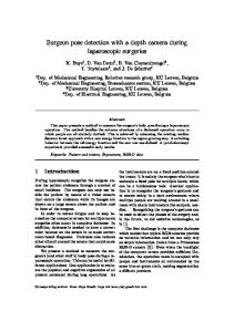
Due to errors in line detection [11], real intersections of converging lines corresponding to one vanishing point are distributed around the true vanishing point. We discovered that if these intersections are not too close to the image center, their distribution has very different variances in different directions. This distribution could be approximately interpreted as an elliptical Gaussian distribution. Its minor axis is very short with respect to major axis. Meanwhile, the included angle between the major axis and a line determined by the true vanishing point and the image center is very small. Figure 1a shows an image with line segments converging to TOVPs. Lines corresponding to different vanishing points are shown in different colors. We add noises to these lines so that their intersections do not coincide with the vanishing points. Blue crosses represent intersections of all pairs of detected lines. As shown in Figure 1a, distributions of the blue crosses are approximately elliptical Gaussian distributions around vanishing points respectively.
154
B. Li et al.
v1
150
v2
100 50
v3
0
0
π
2π
θ
(a)
(b)
Fig. 1. (a) An image of converging lines with noise added. The TOVPs v , v , v form a triangle called the TOVPs triangle. Lines corresponding to different vanishing points are shown in different colors. Blue crosses represent intersections of all pairs of detected lines. Orthocenter of the TOVPs triangle coincides with the image center. Altitudes of the TOVPs triangle are shown as blue solid lines. (b) Histogram of angle coordinates of intersections in (a).
Consider distribution of intersections of converging lines corresponding to one vanishing point in a polar coordinate system with origin at the image center. The major axis of the elliptical Gaussian distribution approximately passes through the origin. Angle coordinates of true vanishing points could be obtained by seeking peaks in histogram of angle coordinates of intersections. Figure 1b shows the histogram of angle coordinates of intersections of all pairs of lines in Figure 1a. Three significant peaks correspond to angle coordinates of the three vanishing points in Figure 1a. As discussed in Section 2.2, orthocenter of the TOVPs triangle coincides with the image center, which is considered as origin of the polar coordinate system. Therefore, if angle coordinates of the TOVPs are detected, altitudes of the TOVPs triangle could be obtained. In our method, we detect altitudes of the triangle firstly. Then constraints from these altitudes are used to detect radial coordinates of the TOVPs and focal length simultaneously (described in Section 4). The detected altitudes of the triangle are shown as blue solid lines in Figure 1a.
4 4.1
Approach Detecting Altitudes of the TOVPs Triangle
Let the image center be the origin of a Cartesian coordinate system in the image plane. The Cartesian coordinates of the three vanishing points v , v , v are denoted by (x , y ), (x , y ), (x , y ), respectively. The polar coordinates of v , v , v is denoted by (θ , ρ ) , (θ , ρ ) , (θ , ρ ) , respectively. Polar transformation of the Cartesian coordinates (x, y) is defined as: y θ tan x (4) ρ x y
Simultaneous Vanishing Point Detection and Camera Calibration
155
According to Section 3, angle coordinates of the TOVPs could be detected by seeking peaks in θ-histogram of intersections of all pairs of detected lines. Consider an altitude of the TOVPs triangle v v v , which passes through vertex v . The altitude also passes through the image center, which is defined as origin in the polar coordinate system. Given angle coordinates θ , θ , θ of the three vanishing points, the altitudes are also determined. It can be represented as: x sin θ
y cos θ
0, i
1, 2, 3
(5)
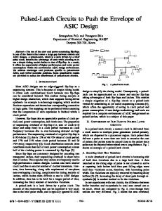
In Figure 2a, intersections of all pairs of detected lines are represented by blue crosses. Figure 2b shows the θ-histogram of the intersections in Figure 2a. The three peaks correspond to the TOVPs. The detected altitudes are shown in Figure 2a. 250 200 150 100 50 0
0
ʌ
�ʌ
T
(b) f = 1020 f = 780 f = 540 f = 300
(a) (c) Fig. 2. (a) A polar coordinate system whose origin is at the image center. Intersections of all pairs of detected lines are marked by blue crosses. Detected altitudes of the TOVPs triangle are shown as solid black lines. (b) θ-histogram of the intersections. (c) A series of TOVPs triangles corresponding to different potential TOVPs and focal length. Detected TOVPs are marked by black squares.
4.2
Constraints from Three Altitudes of the TOVPs Triangle
Consider coordinates of the TOVPs (x , y ), (x , y ), (x , y ) and focal length f as seven unknowns. Since the TOVPs lie on the three detected altitudes respectively, we have the following equations from (5). x sin θ
y sin θ
0, i
1, 2, 3
(6)
156
B. Li et al.
Constraints provided by the detected altitudes of the TOVPs triangle v v v could be represented as an equation system formed by (3) and (6). By solving the equation system, radial coordinates of the TOVPs could be denoted as: ρ where i
x
y
η f,
(7)
1,2,3 and cos(θ θ ) θ ) cos(θ
θ )
η
cos(θ θ ) θ ) cos(θ cos(θ
θ )
η
cos(θ θ ) θ ) cos(θ cos(θ
θ )
η
cos(θ
(8)
Then we obtain: ρ cos θ ρ sin θ
x y
(9)
where i 1,2,3. According to (7) and (9), for different f, the corresponding TOVPs triangles are similar triangles, as shown in Figure 2c. 4.3
Simultaneously Detecting Radial Coordinates of the TOVPs and Focal Length
The intersections of all pairs of detected lines can be divided into three sets according to the nearest altitudes. Since altitudes have already been detected in Section 4.1 as shown in Figure 2a, we project intersections on the corresponding altitudes and use the projections as candidates for the TOVPs. In Figure 2c, projections of intersections are marked by blue crosses. These projections are divided into three sets S , i 1,2,3 according to corresponding altitudes. Consider the distribution of radial coordinates ρ of points in S . Define g (ρ), i 1,2,3 as the distribution function. Radial coordinate ρ of the i-th vanishing point should be the value that maximizes g (ρ). Using (7), we can present this distribution function as a function of f: g (ρ)
g (η f)
(10)
Focal length should be chosen to maximize three g (η f), i We define h(f) as a weighted sum of the three distributions: h(f) where w , i
w g (η f)
w g (η f)
1, 2, 3 simultaneously.
w g (η f)
(11)
1, 2, 3, is the weight of g . f should be a solution of: f
arg max(h(f))
(12)
Simultaneous Vanishing Point Detection and Camera Calibration
157
Since f is measured by pixel and within a bounded range, this equation can be solved by simply enumerating all possible values of f. Given the estimation of f, coordinates of the TOVPs can be calculated by (7) and (9). Computational complexity of our approach is determined by the following: (a) The number of intersections. In an image with n detected lines, the number of intersections could be O(n ), (b) The number of accumulator cells used to detect angle coordinates θ of the vanishing points, denoted by N . (c) The number of accumulator cells used to detect focal length f and radial coordinates ρ of the vanishing points, denoted by N . Generally N and N are no more than 3000. The complexity of this approach can be N N ). O(n
5
Experiments
Many experiments have been done to test validity and correctness of our method. In our tests we use 640 480 images and the image center is considered as the origin of the image space. Accumulator space 0, 2π of θ is discretized into 600 accumulator cells. The range of f is set to 500, 3200 and also discretized into accumulator cells. Weights used in (11) are all set to 1. Since flexibility of our method relies on the constraints provided by the TOVPs, images we use all contain three significant vanishing points. In first experiment, images taken with different focal lengths are used to test our method. Figure 3.a-c show three images of same object with f f f . For images taken with longer focal length, detected lines are much closer to parallel. Many previous methods fail to obtain a reliable focal length when true focal length is relatively long because the vanishing points are close to infinity and difficult to estimate. In our method, novel constraints are used as additional criterion to reduce error. Detected coordinates of vanishing points and focal lengths of Figure 3a-c are shown in Table 1. The vanishing points are not marked in the figures because some of them are too far from image. Focal length errors in the three cases are all below 10%, compared with values calculated by method proposed in [14].
(a)
(b)
(c)
Fig. 3. Images taken with different focal lengths. We have
.
158
B. Li et al.
Table 1. Focal length and vanishing point coordinates of Figure 3a-c estimated by our method Image
f
TOVPs
Fig 3.a
713
(-949,-649), (1009,-693), (17,758)
Fig 3.b
1319
(1728,-1186), (-1767,1108), (34,1516)
Fig 3.c
1880
(2325,1463), (82,2546), (-2345,-1312)
Table 2. Focal length and vanishing point coordinates of Figure 4a-d estimated by our method Image
f
TOVPs
Fig 4.a
713
(28,-1437), (897,443), (-883,408)
Fig 4.b
772
(1166,567), (750,489), (-47,-1146)
Fig 4.c
695
(-891,-366), (631,-217), (-169,1731)
Fig 4.d
721
(882,530), (-1033,-738), (-90,831)
Computition time(sec.)
In second experiment, we test our method by using images of different scenes. Figure 4a and 4b are taken by us. Figure 4c and 4d are from the ZuBuD1 database. Intersections of detected lines in the images are marked by blue crosses. Detected vanishing points are marked by black squares. Detected coordinates of TOVPs and focal lengths are shown in Table 2. We also compared our method with that using EM algorithm [9], which is considered as a quite efficient one among previous methods. Both methods are implemented in MATLAB M-files. They use same line detection algorithm and here we only compare the time cost by vanishing point detection. The results of vanishing point detection using the two methods are comparable. But our method costs much less time. Minimal, average and maximal computational time are reported in Figure 5. Computational time cost by our method in most cases is no more than 0.1 second. Our method can be used in real-time applications. 0.8 0.6
Our method EM
0.4 0.2 0
Min
Mean
Max
Fig. 4. Comparison of computation time
1
http://www.vision.ee.ethz.ch/showroom/zubud
Simultaneous Vanishing Point Detection and Camera Calibration
(a)
(b)
(c)
(d)
159
Fig. 4. Experiments on images of both indoor and outdoor scenes. (a) and (b) are taken by us. (c) and (d) are from the ZuBuD database. Intersections of detected lines in the images are marked by blue crosses. Detected vanishing points are marked by black squares.
5
Conclusions
A novel method for simultaneous vanishing point detection and camera calibration is proposed in this paper. The method can be described in two steps: Firstly, angle coordinates of the three vanishing points are detected. Secondly, focal length and radial coordinates of the vanishing points are estimated simultaneously. This method is based on an observation that angle coordinates of vanishing points can be estimated easily and robustly. Altitudes of the TOVPs triangle may be determined from the detected angle coordinates of the TOVPs. The three altitudes provide constraints on both vanishing points and focal length, which largely simplifies the
160
B. Li et al.
estimation problem of vanishing points and focal length. Compared to previous methods, our method requires much less time and memory.
Acknowledgement This work was supported in part by the NSFC Grant (No.61075034), the NHTRDP 863 Grant No. 2009AA01Z329, and the NHTRDP 863 Grant No.2009AA012105.
References 1. 2. 3.
4. 5. 6. 7. 8. 9. 10. 11. 12. 13.
14.
Barnard, S.T.: Interpreting perspective images. Artificial Intelligence 21, 435–462 (1983) Caprile, B., Torre, V.: Using vanishing points for camera calibration. International Journal of Computer Vision 4, 127–140 (1990) Cipolla, R., Drummond, T., Robertson, D.: Camera calibration from vanishing points in images of architectural scenes. In: Proc. British Machine Vision Conference, vol. 2, pp. 382–392 (1999) Van Gool, L., Zeng, G., Van Den Borre, F., Müller, P.: Towards mass-produced building models. In: Photogrammetric Image Analysis, PIA (2007) Hartley, R., Zisserman, A.: Multiple view geometry in computer vision. Cambridge University Press, Cambridge (2003) Van Den Heuvel, F.A.: Vanishing point detection for architectural photogrammetry. International Archives of Photogrammetry and Remote Sensing 32(Part 5), 652–659 (1998) Hedau, V., Hoiem, D., Forsyth, D.: Recovering the spatial layout of cluttered rooms. In: Proc. International Conference on Computer Vision (2009) Kong, H., Audibert, J., Ponce, J.: Vanishing point detection for road detection. In: Proc. IEEE Conf. Computer Vision and Pattern Recognition, pp. 96–103 (2009) Košecká, J., Zhang, W.: Video compass. In: Heyden, A., Sparr, G., Nielsen, M., Johansen, P. (eds.) ECCV 2002. LNCS, vol. 2353, pp. 657–673. Springer, Heidelberg (2002) Rother, C.: A new approach for vanishing point detection in architectural environments. Image and Vision Computing 20, 647–655 (2002) Shufelt, J.A.: Performance evaluation and analysis of vanishing point detection Techniques. IEEE Trans. Pattern Analysis and Machine Intelligence 21(3), 282–288 (1999) Tardif, J.: Non-iterative approach for fast and accurate vanishing point detection. In: Proc. International Conference on Computer Vision (2009) Tuytelaars, T., Van Gool, L., Proesmans, M., Moons, T.: The cascaded Hough transform as an aid in aerial image interpretation. In: Proc. International Conference on Computer Vision, pp. 67–72 (1998) Zhang, Z.: Flexible camera calibration by viewing a plane from unknown orientations. In: Proc. International Conference on Computer Vision (1999)