Operator’s Manual Supplement
7000 Series 3–Source Automatic Transfer System with Acc. 111A Standby Generator to Generator Controls NOTES
DANGER is used in this manual to warn of high voltages capable of causing shock, burns, or death.
■
!
WARNING is used in this manual to warn of possible personal injury.
Refer to the outline and wiring drawings provided with the 7000 Series ATS for installation and connection details and accessories.
■
Refer to the Operator’s Manual provided with your generator ATS (7000 Series) for general installation information.
■
!
CAUTION is used in this manual to warn of possible equipment damage.
N
ATS 2 Main ATS (provided separately) E
L
Generator ATS (7000 Series with Acc. 111A) E
N
Refer to the Operator’s Manual provided with the main ATS for general installation information.
General Application
Utility
L
■
Refer to the Controller User’s Guide 381333–126 for status display messages, time delays, pickup and dropout settings, and adjustments.
ATS 1
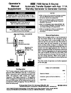
Where loads are highly critical, it may be necessary to have the double backup of two emergency sources. Thus, if one doesn’t start, is slow starting, or fails, the other one will start and carry the load. The controls in this system keep the load connected to the normal source, usually a utility, as long as it is adequate. If the normal source fails or drops below acceptable levels, the controls start both engine generator sets. The first to produce acceptable voltage and frequency is selected by ATS 1. If the first engine generator set operates properly after a pre–set period, the other set is shut down; it will be started up and put on the line if the first one fails at any time during operation. When normal power is restored, the load is retransferred to normal by the main ATS 2. The other modes of operation are further explained on the next page.
Configuration The 3–source automatic transfer system consists of a generator ATS1 (7000 Series with Acc. 111A controls) used in conjunction with a separately provided main ATS2. The generator ATS1 sources are Engine– Generator 1 and Engine–Generator 2. The generator ATS1 load feeds the emergency side of main ATS2. So, the main ATS2 sources are the utility (normal) and the load feed from ATS1 (emergency). The main ATS2 load feeds the facility loads.
TABLE OF CONTENTS page Operation Modes . . . . . . . . . . . . . . . . . . . . . . . . 2 Indicators Lights and Control Switches . . . . . 3 Logic Relay . . . . . . . . . . . . . . . . . . . . . . . . . . . . . 4
50 Hanover Road, Florham Park, New Jersey 07932–1591 USA 1 800 937–2726 (ASCO), for service call 1 800 800–2726 (ASCO) www.asco.com ASCO POWER TECHNOLOGIES CANADA PO Box 1238, 17 Airport Road, Brantford, Ontario, Canada N3T 5T3 telephone 519 758–8450, fax 519 758–0876, for service call 1 888 234–2726 (ASCO) www.asco.ca
381333–273 B
Operation Modes There are several different operating modes of the 3–source automatic transfer system. Figure 1 on page 3 shows the Source Selector control switch which determines the operating modes.
If Generator 1 fails to start or fails while connected to the load, Generator 2 is started. When it attains rated voltage and frequency, it causes the generator ATS1 to transfer to it. The facility loads are now carried by the other generator.
Normal Mode
Generator 2 Mode
With acceptable utility power available at the normal side of main ATS2, the utility provides electrical power to the facility loads.
With the Source Selector control switch in the Gen 2 position, only Generator 2 is signalled to start upon utility failure. When Generator 2 attains rated voltage and frequency it causes the generator ATS1 to transfer to it (if not already connected to it). When the main ATS2 senses acceptable emergency power it transfers the facility loads to the emergency source (Generator 2).
Automatic Mode With the Source Selector control switch in the Auto position, both generators are signalled to start upon utility failure. The first generator to attain rated voltage and frequency causes the generator ATS1 to transfer to that generator (if not already connected to it). Likewise, when the main ATS2 senses acceptable emergency power it transfers the facility loads to the emergency source (either Generator 1 or Generator 2).
If Generator 2 fails to start or fails while connected to the load, Generator 1 is started. When it attains rated voltage and frequency, it causes the generator ATS1 to transfer to it. The facility loads are now carried by the other generator.
The other (unloaded) generator begins a cooldown time delay and then shuts down because it is not needed.
Simulated Utility Failure Operation of the Transfer Test control switch on the main ATS2 simulates a utility failure. The 3–source automatic transfer system operates according to the position (mode) of the Source Selector control switch on generator ATS1. If the running generator fails during the test, the main ATS2 immediately transfers the facility loads back to the utility. If the utility fails during the test, the running generator continues to feed facility loads until utility returns.
If the connected generator fails, the other generator is restarted. When it attains rated voltage and frequency, it causes the generator ATS1 to transfer to it. The facility loads are now carried by the other generator. Alternate Mode With the Source Selector control switch in the Alternate position, Generator 1 and Generator 2 alternate in their starting preference. If Generator 1 is providing emergency power this time, next time Generator 2 will be started, and vice versa.
Operation of the Retransfer Delay Bypass control switch on the main ATS2 immediately transfers the facility loads back to the utility. Engine–Generator Exerciser When the Source Selector control switch is in the Alternate position with the engine exerciser initiated via the transfer switch the generator will exercise during this event. The sequence will then alternate between Generator 1 and Generator 2 each time the exercise period is initiated.
If the preferred generator fails to start or fails while connected to the load, the other generator is started. When it attains rated voltage and frequency, it causes the generator ATS1 to transfer to it. The facility loads are now carried by the other generator.
If a power outage occurs after Generator 1 has completed an exercise period, Generator 2 will assume the load. Generator 1 would then assume load during the next exercise period. The sequence will continue to alternate between Generator 1 and Generator 2 each time start signals are removed and initiated.
Generator 1 Mode
If a power outage occurs during the Generator 1 exercise period, Generator 1 will continue to assume the load. Generator 2 would then assume load during the next exercise period. The sequence will continue to alternate between Generator 1 and Generator 2 each time start signals are removed and initiated.
With the Source Selector control switch in the Gen 1 position, only Generator 1 is signalled to start upon utility failure. When Generator 1 attains rated voltage and frequency it causes the generator ATS1 to transfer to it (if not already connected to it). When the main ATS2 senses acceptable emergency power it transfers the facility loads to the emergency source (Generator 1).
With the Source Selector control switch in the Auto position, both generators are signaled to start upon utility failure. The first generator to attain voltage and frequency will continue to be exercised. The other (unloaded) generator begins a cooldown time delay and then shuts down because it is not required. The generator logic does not differentiate between a start signal initiated from an outage or an engine exerciser event.
2
Automatic Transfer Switch
Transfer Switch Transfer Switch Generator 1 Connected Connected Start To To Manual Auto Generator 1 Generator 2
RED
observe these lights
Generator 1 Source Accepted
GREEN
RED
Generator 2 Source Accepted
Source Selector Auto
Alternate
Gen 2
Gen 1
Generator 2 Start Auto
Programmable Controller Failed
Manual
GREEN
RED
Figure 1. Door–mounted indicators and controls.
Indicator Lights
Control Switches
Five door–mounted indicator lights show the position of generator ATS1, which generator sources are available (acceptable), and one alarm condition.
The door–mounted Source Selector control switch provides four operating modes. Two Generator Start control switches provide either automatic or manual operation of each generator.
Indicator Transfer Switch Connected To Generator 1 Transfer Switch Connected To Generator 2 Generator 1 Source Available Generator 2 Source Available Programmable Controller Failed
ON Meaning Generator ATS1 is feeding its load from the Generator 1 source. Generator ATS1 is feeding its load from the Generator 2 source. Generator 1 source voltage and frequency are acceptable. Group 5 Controller constantly monitors generator 1. Generator 2 source voltage and frequency are acceptable. Group 5 Controller constantly monitors generator 2. The internal Logic Relay may not be functional. Refer to page 4 for troubleshooting.
Control
Meaning Auto Both generators 1 & 2 start upon utility failure. Alternate Generators 1 & 2 alternate in their starting preference. Source Generator 1 Selector Only generator 1 starts upon utility failure. Generator 2 Only generator 2 starts upon utility failure. Auto Generator 1 starts automatically as determined by the position of the Source Selector control switch and utility status. Generator 1 Manual Start Generator 1 starts and runs in this position. To return it to automatic operation, turn the control switch to Auto position. Auto Generator 2 starts automatically as determined by the position of the Source Selector control switch and utility status. Generator 2 Manual Start Generator 2 starts and runs in this position. To return it to automatic operation, turn the control switch to Auto position.
3
Logic Relay A Logic Relay is used to provide many of the Accessory 111A control functions and time delays. Use extreme caution when checking the relay. Do not touch any power terminals; shock, burns, or death could result!
Troubleshooting
Figure 2. Internal Logic Relay.
If the Programmable Controller Failed red light comes on, the Logic Relay may not be functional. It should be checked to see if it is in the RUN mode.
Time Delay Settings Time Delay
If the display is blank, then there is either a problem with the power supply to the logic relay or the logic relay is defective. Verify that control power to the logic relay is acceptable (18---30 V dc). If the voltage is OK, then the logic relay is not functioning and must be replaced.
T1 T2 T3
If the display is active, but lists several language choices, then follow this procedure to put the logic relay in RUN mode:
T4
NOTE: If the logic relay does not list several language choices but instead shows STOP on line 2 of the display, then start at step 6 below. 1. Use the up (Z1) and down (Z3) arrows to scroll to the language to be selected.
Generator 1 Cooldown Generator 2 Cooldown Generator 1 Failure Generator 2 Failure
Factory Setting
Setting Range
5 minutes
0 to 99 min.
5 minutes
0 to 99 min.
30 seconds
0 to 99 sec.
30 seconds
0 to 99 sec.
!
Changes to these settings may affect the normal operaton of the automatic transfer switch.
To Change a Timer Delay Settings
2. Press Sel./OK. A diamond should appear to the right of the language.
The timer values can be changes through the keypad on the logic relay. 1. Select PARAMET from the main menu. 2. Press Sel./OK.
3. Press ESC. A screen asking you to set the time should appear. The time functions are not used, so it is not necessary to set the correct time. 4. Press Sel./OK several times to accept the default values (or use keys to set correct day & time).
3. Use the up (Z1) and down (Z3) arrows to scroll to the timer to be changed.
5. Press ESC to leave the time menu and return to the main screen.
4. Press Sel./OK to select the timer. 5. Use the left (Z4) and right (Z2) arrows to move between the values to be changed.
6. Press Sel./OK to display the main menu. 7. Use the up (Z1) and down (Z3) arrows to select RUN/STOP. 8. Press Sel./OK.
6. Use the up (Z1) and down (Z3) arrows to change the value. 7. Press Sel./OK to save the changes, or press ESC to retain the previous setting.
9. Use the up (Z1) and down (Z3) arrows to select YES.
8. Press ESC to leave the parameter menu and return to the main screen.
10. Press Sel./OK. 11. Press ESC to return to the main screen.
4