Reconfigurable Low Pass Filter with Automatic Frequency Tuning for WCDMA and GSM Application Chen Jiang, Renzhong Xie,Weinan Li, Yumei Huang * and Zhiliang Hong
State Key Laboratory of ASIC and Systems, FudanUniversity, Shanghai201203, China * Email:
[email protected] A reconfigurable baseband low-pass filter (LPF) with automatic cut-off frequency tuning for WCDMA and GSM application is presented. Cut-off frequencies of 2.1MHz and 200-KHz, and out of band IIP3 at least 20.8dBm and 22.7dBm are achieved under WCDMA and GSM mode respectively. The in band ripple is below 0.5dB in both modes. By utilizing digital frequency tuning technique, a cut-off frequency error of less than 2.5% is obtained. The total tuning time is about 5.5I1S. The LPF is fabricated in SMIC 0.13!lffi CMOS technology with chip area of 0.35mm2, and the current consumptions are 8.3mA and 1. lmA for WCDMA mode and GSM mode respectively under a power supply of 1.5V. Abstract:
I
iJl!
L ___
�-- :
L-------------------------
------------A��i�g B�;;b��d
__________
J
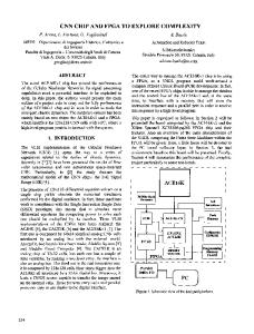
Figure I. Block Diagram of The Multi-mode Analog Baseband
1. Introduction
Channel select filter is an important building block for analog baseband circuits in receivers. Its main purpose is to select desired signals and provide anti-aliasing for the following ADC. A reconfigurable LPF designed for WCDMA and GSM dual-mode receiver analog baseband circuit is presented in this paper. The architecture of the multi-mode baseband circuit is shown in Fig. I. It is consist of Programmable-gain amplifiers (PGA) with DC Offset Cancellation (DCOC) blocks as well as the reconfigurable LPF with Automatic Frequency Tuning (AFT) block. There are two stages of PGAs in this baseband circuit. The first one is placed in front of the filter in order to suppress the noise caused by the large resistors in the filter, and the second one is placed after the filter for good in-channel linearity. The filter is a fourth-order low-pass Chebyshev filter with cut-off frequencies of 2. IMHz and 200-KHz for WCDMA and GSM applications respectively. Under different process comers, the value of resistors and capacitors in the LPF may change largely, thus the cut-off frequency may deviate from the designed value. To maintain a precise cut-off frequency, a DFT circuit is proposed. The rest of this paper is organized as follows. Section 2 describes design of the configurable LPF. Section 3 describes the DFT technique for the filter. Measurement results are given in Section 4 and a summary in Section 5.
978-1-61284-193-9/11/$26.00
�-------i
!------------------------------------------------------------
2011IEEE
2. Design of ReconfigurabJe LPF 2.1 LPF Structure
Gm-C filter and active-RC filter are two commonly used types of continuous-time filters [ I]. Gm-C filters are generally more flexible compared to active-RC filters, but as most Gm-C filters are implemented open looped, which causes poor linearity. At the same time, active components in Gm-C filters often lead to a worse noise performance. For these reasons, active-RC structure is chosen here. If each branch in a LC ladder filter is represented with an opamp with feedback elements, we can get an active ladder filter [2] shown in Fig. 2. It is well known that LC ladder filters are fairly insensitive to errors on the value of L and C, which can be used to overcome mismatch of capacitors and resistors in active-RC filters. The capacitors in the filter are implemented as capacitor arrays prepared for frequency tuning in order to compensate process variation. Capacitor arrays are shared under both WCDMA and GSM mode and configurable cut-off frequency is realized by changing resistors connected in the circuit, which is shown in Fig. 2. To make cut-off frequency error introduced by capacitor array quantization error within 2%, capacitor arrays are composed of a fixed
capacitor and six tuning capacitors in binary formation, thus a 6-bit tuning word is needed.
VDD
.. ..... ........ ..............................
Vinp Vinn
::-:-:::E1-...-j ... -1 1
········ ·····························
_
t Vb2
Vb2
GND
Figure 3. Reconfigurable Opamp Figure 2.Schematic of an Active-RC Ladder Filter Since noise performance largely depends on the resistances in the LPF, by adjusting the resistance, the noise can be optimizes. However, adjusting the resistance means changing the gain of certain branches, which may affect the transfer function of the LPF. It is necessary to make sure that the whole LPF transfer function remains the same though the gain of some branches is changed after the resistors are adjusted [2]. 2.2 Opamp Design
It is obvious that requirement for opamp under different modes is different. For power saving consideration, a configurable opamp is designed to suit both modes. The structure of the configurable opamp is shown in Fig. 3. The first stage of the opamp encompasses two sets of transistors that are specially designed for WCDMA and GSM modes. A control signal MODE, as denoted in Fig. 3, controls which set of transistors to be connected into the circuit and which set is disabled. The gates of disabled PMOS transistors are connected to V DD and gates of disabled NMOS transistors are connected to GND. In this way, disabled transistors are all cut off. Under WCDMA mode, opamp needs a relatively larger transconductance for sake of a higher cut-off frequency. This means the transistor set designed for WCDMA mode will be more sensitive to the influence of switches than that in GSM mode. So in order to obtain a good performance, switches should be moved from WCDMA mode circuit to GSM mode circuit as many as possible. Another issue is that, in the LPF shown in Fig. 2, values of the capacitors are different, which means opamp should also be able to accommodate to different load capacitances. By connecting different number of
transistors in parallel, we can get different transconductances. In this way, we can make the transconductance of the second stage of opamp reconfigurable for different loads. 3. Automatic Cut-off Frequency Tuning Technique
Due to process variation, the values of resistors and capacitors in the LPF could have a variation of 20%, thus cut-off frequency could be largely deviated from the designed value. So a tuning circuit is needed to ensure a precise cut-off frequency. Here we use a master-slave method to realize automatic frequency tuning [3].
Figure 4. AFT Circuit Analog Part The AFT circuit is composed of both analog part and digital part. Schematic of analog part is shown in Fig. 4. The first opamp is used as a regulator to generate a reference current:
Ire!
Vre! Rslave
=--
(1)
A current mirror copies this reference current to charge the slave capacitor array. Assuming that the charging time is Llt, then after charging, the voltage on the capacitor array is:
V::ap
=
IchargeM Cslave
=
klrej!1t Cslave
(2)
k is the ratio of the current mirror. After charging, V cap is compared with the reference voltage, the result is sent to digital part of AFT circuit. Then the digital part will change the capacitor array tuning word according to the comparison result. When the voltage of capacitor array equals to the reference voltage, according to equation (1) and equation (2), we will get:
RslaveCslave
=
k!1t
(3)
A very precise M can be obtained with the clock signal. So if master resistors and capacitors in LPF circuit match well with the slave devices in AFT circuit, a very precise cut-off frequency can be obtained. As shown in Fig. 4, switch S1 is designed for discharging the capacitor array before each comparison period. S2_W and S2_G are designed for WCDMA and GSM modes respectively. Only one of them will be manipulated by AFT digital part according to the mode adopted.
s
�
� i . i �::f.................+....... reset
s
Camparator output Sample
T
l
nnno
nonnnno
b l hL-' amp,
4. Experiment Results
The chip is implemented with SMIC 0.13/lffi CMOS technology, and the micrograph is shown in Fig. 6. The LPF occupies about 0.35mm2 area and consumes about 8.3mA from a 1.5V supply under WCDMA mode and about l.1mA under GSM mode. The AFT part takes up only about 0.04mm2 area and draws about 300uA current from 1.5V supply under both modes, which is powered off when tuning is completed.
�r-l� '----_-----'I
____�____��__ charge
nnnnnnnnnnnnnn
comparison periods are used for circuit to become stable after reset or power up, then the total automatic tuning time is 5.54I1S. Same opamp is used as regulator and comparator in AFT analog part (shown in Fig. 4) to cancel the influence of opamp input offset voltage. After tuning is fmished, the EN signal will become 0 to power down opamps and current mirror in AFT analog part to save power. If capacitor array quantization error is kept within 2%, master and slave resistor mismatch is less than 0.5%, master and slave capacitor mismatch is small than 0.3%, other error sources like current mirror mismatch and opamp mismatch is below 1%, then the cut-off frequency error will be under 5%.
__ __
nonnnnnnnno
\
I
____
Figure 5. Timing Diagram of AFT Digital Part Digital part of AFT circuit is to generate control signal for switches in AFT analog part and generate the next tuning word for slave capacitor array according to the previous compare result. The timing diagram of AFT digital part is shown in Fig. 5. There are 16 clock cycles within one comparison period. Charging takes 4 clock cycles and before each charging, capacitor array is discharged at fIrst. This discharge takes 2 clock cycles, denoted as reset in Fig. 5. To achieve high precision, switch S2 is on during the reset period in order to provide enough time for charging current to become stable. 5 clock cycles are provided for comparator to generate a stable output. After that, the result will be sampled. A successive approximation method is used to generate the next tuning word for slave capacitor array, so it will take 6 comparison periods to get the fInal 6-bit tuning word. The clock frequency is 26MHz, and 3
Figure 6. Chip Micrograph Fig. 7 and Fig. 8 show the frequency response of the LPF before and after AFT under both modes. The frequency error is 2.4% and 1.5% for WCDMA mode and GSM mode respectively. Fig. 9 shows the result of two-tone test under WCDMA mode. The frequencies of the two tones are 10MHz and 21MHz, and input powers are both -12dBm. The test reflects the out of band linearity of the LPF. This test is operated on the whole analog baseband depicted in Fig. I with gain of both stages of PGA confIgured to 0 dB. So the linearity of LPF alone should be better than the test results. Table 1 tabulates details about the low-pass fIlter and AFT circuit test results.
Frequency Response in WCDMA mode
1
20--,-----------'---------,
II
------
t
---
-20
ro "0 Q) "0
2
·c Cl '" :2
Before AFT After AFT
LPF Mode Type
\�
-40 -60 -80 -100 1E6
1E7
Frequency
1E8
Hz
Figure 7.Frequency Response in WCDMA Mode. Measured cut-off Frequency is 3.0MHz before AFT and 2.05MHz after AFT.
Frequency Response in GSM mode
20--,------,--,
ro "0 Q) "0
2
·c Cl '" :2
-20 -40 -60 -80 -100 1E5
1E6
Frequency
1E7
Hz
Figure 8.Frequency Response in GSM Mode. Measured cut-off Frequency is 300KHz before AFT and 197KHz after AFT.
Figure 9.Test Result of Out of Band IIP3
Table I.Summary of LPF Performance WCDMA 4th Order Chebyshev 2.05MHz 0.4 <0.5 >20.8 1.5 12.4
Cutoff Freq Gain [dB] Inband Ripple fdBl IIP3 Out of Band [dBm] Supply Voltage [V ] Power Consumption fmWl AFT Mode WCDMA Tuning Time [�s] 5.54 2.4% Freq Error Power Consumption [mW] 0.45
GSM 4th Order Chebyshev 197KHz 0.15 <0.5 >22.7 1.5 1.6 GSM 5.54 1.5% 0.45
5. Summary
This paper presents design of a configurable baseband low-pass filter with automatic cut-off frequency tuning for WCDMA and GSM application. The low-pass filter is fabricated in SMIC 0.13� CMOS technology and takes about 0.35mm2 area. Under WCDMA mode, it realizes a cut-off frequency of 2.05MHz with 12.4mW power consumption; under GSM mode, it realizes a cut-off frequency of200-KHz with a power consumption of 1.6mW. After automatic frequency tuning, precise cut-off frequency with less than 2.5% error is achieved. References
[1] B.Nauta, "Analog CMOS Filters", Kluwer Academic Publishers (1993) [2] M. Banu and Y. Tsividis, "An Elliptic Continuous-Time CMOS Filter with On-Chip Automatic tuning", Solid-State Circuits, IEEE Journal of, 6, p.1114(1985). [3] Liang Zou, Kefeng Han,Youchun Liao,Hao Min and Zhangwen Tang,"A 12th Order Active-RC Filter with Automatic Frequency Tuning for DV B Tuner Applications", IEEE Asian Solid-State Circuits Conference, p.281(2008) [4] Seyeob Kim, Bonkee Kim, Min-Su Jeong, Jung-Hwan Lee, Youngho Cho, Tae Wook Kim and Bo-Eun Kim, "A 43dB ACR Low-pass Filter with Automatic Tuning for Low-IF Conversion DAB/T-DMB Tuner IC", IEEE European Solid-State Circuits Conference, p.319(2005)