DESIGN METHOD OF AN OPTIMAL INDUCTION HEATER CAPACITANCE FOR MAXIMUM POWER DISSIPATION AND MINIMUM POWER LOSS CAUSED BY ESR Jung-gi Lee, Sun-kyoung Lim, Kwang-hee Nam ∗ and Dong-ik Choi ∗∗
∗ Department of Electrical Engineering, POSTECH University, Hyoja San-31, Pohang, 790-784 Republic of Korea. Tel:(82)54-279-2218, Fax:(82)54-279-5699, E-mail:
[email protected] ∗∗
POSCO Gwangyang Works, 700, Gumho-dong, Gwangyang-si, Jeonnam, 541-711, Korea.
Abstract: In the design of a parallel resonant induction heating system, choosing a proper capacitance for the resonant circuit is quite important. The capacitance affects the resonant frequency, output power, Q-factor, heating efficiency and power factor. In this paper, the important role of equivalent series resistance (ESR) in the choice of capacitance is recognized. Without the effort of reducing temperature rise of the capacitor, the life time of capacitor tends to decrease rapidly. This paper, therefore, presents a method of finding an optimal value of the capacitor under voltage constraint for maximizing the output power of an induction heater, while minimizing the power loss of the capacitor at the same time. Based on the equivalent circuit model of an induction heating system, the output power, and the capacitor losses are calculated. The voltage constraint comes from the voltage ratings of the capacitor bank and the switching devices of the inverter. The effectiveness of the proposed method is verified by simulations and experiments. Keywords: Induction heating, Equivalent series resistance, Design
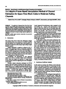
1. INTRODUCTION Induction heating is widely used in metal industry for melting or heating of thin slab in a continuous casting plant because of good heating efficiency, high production rate, and clean working environments. A typical parallel resonant inverter circuit for induction heater is shown in Fig. 1. The phase controlled rectifier provides a constant DC current source. The H-bridge inverter consists of
four thyristors and a parallel resonant circuit comprised capacitor bank and heating coil. Thyristors are naturally commutated by the ac current flowing through the resonant circuit. Therefore, this type of inverter called as a load commutated inverter (Y. kwon, 1999; F.P. Dawson, 1991; R. Bonert 1994). The induction heater was kept up the metal slab of 1100o C for the next milling process. In the parallel resonant inverter, if the switching frequency is
3-phase Rectifier
Idc
H-bridge Inverter
is
DC link Inductor
+-
S
Firing angle a, DC link current Idc control
Output Power P
Heating Coil
vC Capacitor Bank
(a1, a2, a3, a4, a5, a6 ) Power Reference P*
iL
VoltageLimiter Vmax
Heated Slab
vC
-Vmax
Output Power Calulator
1 2
Pout = VC I s cosa
vC is
Fig. 1. Block diagram of induction heating system. closer to the resonant frequency for high power, higher voltage is generated at capacitor bank (F.P. Dawson, 1991). However, due to the limit in the voltage tolerance of the capacitor bank, the inverter output voltage vC needs to be limited below the rated voltage Vmax . One method of limiting vC is to reduce the DC-link current Idc by increasing the firing angle of the rectifier. However, it results in the decrease of Idc , thereby the decrease of the output power.
elled as an inductance plus a series resistance, and the capacitor bank is modelled as a pure capacitance with an equivalent series resistance(ESR) (Dec.2002 issue of Practical Wireless). Utilizing this model, the output power of the induction heater and the power loss in the capacitor are derived as functions of capacitance. An optimal value of the capacitance under the voltage constraint is found with the help of Lagrange multiplier (D.G. Luenberger, 1989).
At the mini-mill in a POSCO steel plant, eight induction heaters of load commutated type were installed to heat thin slabs for next milling process in the continuous casting plant. The rated output power of each induction heater is 1.5 MW. However, there were two problems: One was the insufficiency in the output power, and the other was the frequent damages of the capacitor bank. Insufficiency in output power was caused by a poor power factor of the inverter. On the other hand, the damage to the capacitor bank was due to a little voltage margin between vC and Vmax , and it resulted in a large power dissipation in the capacitor causing a high temperature rise.
This procedure looks very useful in the design of the induction heating system, specifically, in determining the size of capacitor bank. All the parameters used in this work come from the induction heater operating in POSCO.
The capacitance of the capacitor bank affects the overall operating factors of induction heater such as resonant frequency, Q-factor, efficiency, and power factor (P. Jain,1988; E. J. Davis,1979; E. J. Davies, 1990). Hence, in this work, we propose a method of choosing an optimal capacitance value Copt , which maximizes the output power, and at the same time, minimizes the capacitor loss. Firstly, an equivalent model of the induction heater is developed based on previous works (Y. kwon, 1999; T. Imai, 1997; E. J. Davis, 1979; E. J. Davies, 1990). The heating coil and slab is mod-
2. EQUIVALENT CIRCUIT AND POWER EQUATIONS In general, the heating coil and the load are modelled as a transformer with a single turn secondary winding as shown in Fig. 3(a). Almost all magnetic flux generated by the induction coil (primary winding) penetrates into the slab (secondary winding). Hence, in the secondary circuit no leakage inductance appears and the coupling coefficient is equal to one. The secondary circuit can be moved to the primary part as shown in Fig. 3(b) (E. J. Davis, 1979). Denoting the mutual inductance by LM , it follows that
L1 = L l + N L M , LM , L2 = N
(1) (2)
1.2 × 10⁻⁶ Ω · F to 1.5 × 10⁻⁶ Ω · F (Dec.2002 issue of Practical Wireless).
Fig. 2. Model of slab for one turn coil. where L1 and Ll denote the inductance of the heating coil and the leakage inductance, respectively. Using Wheeler’s formula (Harold A. Wheeler, 1942), the inductance of the heating coil is calculated as follows: L1 (µH) =
r2 × N 2 , 9r + 10h
(3)
where r is the radius, N is the turn number and h is the height of the coil. The slab resistance RL for one turn coil is given by RL = ρ
L 2(w + 2b) =ρ , A lδ
(4)
where L and A are length and area of eddy current, l is the effective length of the slab occupied by one turn coil and b and w are defined in Fig. 2 (S. Zinn, 1988), δ and ρ are skin depth almost distributed over the surface of slab and electrical resistivity of the material. Simplified equivalent model for a transformer can be represented in Fig. 3(c) by an equivalent inductance Leq and resistance Req (Y. kwon, 1999; E. J. Davis, 1979). These equivalent parameters depend on several variables including the shape of the heating coil, the spacing between the coil and slab, the electrical conductivity and magnetic permeability of the slab, and the angular frequency of the varying current ωs (E. J. Davis, 1979).
2
(5)
2
(6)
Leq = L1 − A L2 ,
Req = R1 + A RL ,
where R1 denotes the resistance of the heating coil, RL denotes p the resistance of the heated slab, ± and A = ωs LM ωs 2 L2 2 + RL 2 . It is noted that the inductance of heating coil L1 is not affected by the existence of the slab in the heating coil, since at about 1100o C temperature the permeability of the iron slab is equal to that of air, i.e., µ = 4π × 10−7 (H/m) (E. J. Davis, 1979). To represent the power dissipation in the capacitor bank, it is modelled by a pure capacitance C and an equivalent series resistance (ESR) RESR . It is noted that RESR is inversely proportional to the ± capacitance, hence, it is modelled as RESR = k C, where k is a coefficient of ESR ranged from
Fig. 3. (a) Based circuit of the induction heater. (b) Equivalent circuit of the induction heater based on a transformer concept. (c) Simplified equivalent circuit of the induction heater. A useful variable to calculate the power is a total impedance seen from the impedance of equivalent circuit in Fig. 3(c) (H. Kojima, 1990). The total impedance is given by
(ZC + ZESR ) · (ZL + ZR ) ZL + ZR + ZC + ZESR (ωs kReq + ωs Leq ) + j(ωs2 Leq k − Req ) = ,(7) ωs (CReq + k) + j(ωs Leq C − 1) ± where ZL = jωs Leq , ZC = 1 jωs C, ZR = Req , and ZESR = RESR = k/C. Zt =
The rectifier and H-bridge inverter of the induction heater are represented by a square waved current source whose magnitude is equal to the DC-link current Idc . Therefore, the current source expanded in a fourier series is described as follows: is (t) =
∞ X 4Idc sin nωs t nπ n−1
n = 1, 3, 5, . . .
The fundamental component of the square waved current source is given by
.(8)
is (t) =
4 Idc sin ωs t = Is sin ωs t, π
(9)
where Is = 4Idc /π is a peak of is . The current through Req and RESR are represented by iL and iC , respectively. The phasor expression of iL and iC are described as follows:
ZC + ZESR VC = Is ,(10) ZL + Z R ZL + ZR + ZC + ZESR VC ZL + Z R IC = = (11) Is , ZC + ZESR ZL + ZR + ZC + ZESR IL =
where VC and Is are phasors of vC and is and VC = Z t · I s . In Fig. 3(b), the power consumption generate equivalent resistor Req and ESR RESR of the capacitor bank. therefore, the output power of the induction heater Pout and the capacitor loss Ploss are given by
Pout (C) =
µ
I √L 2
¶2
Zeq
¯ ¯2 ¯ 2 ZC + ZESR 1 ¯¯ ¯ I Zeq (12) = ¯ 2 ZL + ZR + ZC + ZESR ¯ s ¯ ¯2 ¯ 2 ¯ 8Idc ωs k − j ¯ ¯ ¡ ¢ = 2 ¯ ¯ Req , π ¯ ωs C Req + Ck + j(ωs2 CLeq − 1) ¯ ¶2 µ IC ZESR Ploss (C) = √ 2 ¯2 ¯ ¯ 2 1 ¯¯ ZL + Z R ¯ I ZESR = ¯ (13) 2 ZL + ZR + ZC + ZESR ¯ s ¯2 ¯ ¯ k 2 ¯ 8Idc ωs C(Req + jωs Leq ) ¯ ¯ ¡ ¢ = 2 ¯ , ¯ π ¯ ωs C Req + Ck + j(ωs2 CLeq − 1) ¯ C
where VC is the peak of vC , Vmax is rated voltage of the capacitor bank, and Zt is total impedance of capacitor bank and heating parts. One can see that |Zt (j1.1ω 0 )| is also a function of capacitance, ±p since ω0 = 1 Leq C.
The aim is to find an optimal capacitance value that maximize the output power of the induction heater and minimize the capacitor losses simultaneously under the voltage constraint (14). If the cost function is selected as Pout − Ploss , maximizing Pout − Ploss is equivalent to maximizing Pout and at the same time minimizing Ploss . maximizing subject to
Pout − Ploss
|Zt (j1.1ω0 )| · ( π4 Idc ) ≤ Vmax .
It leads to apply Kuhn-Tucker theorem (D.G. Luenberger, 1989). Firstly, the cost function is defined by
J(C) = Pout (C) − Ploss (C) ³ π ´ + λ · Vmax − |Zt (j1.1ω0 )| · Idc ,(15) 4 where λ ≥ 0 is the Lagrange multiplier. The maximum point is found under the following conditions,
where IL and IC denote the peak of iL and iC , respectively (S. Dieckerhoff, 1999). It is noted that Pout and Ploss are function of capacitance C, since all the parameters except capacitance are known values in (12) and (13). 3. OPTIMAL CAPACITANCE FOR MAXIMIZING OUTPUT POWER AND MINIMIZING CAPACITOR LOSS In the load commutated inverter, the switching frequency of the inverter must be higher than the resonant frequency of the L-C load to guarantee commutation of the thyristors (R. Bonert, 1994). Hence, for more suitable value for the inverter while working close to the resonant frequency, we let ωs = 1.1ω0 , then the voltage constraint is given Fig. 4. The output power Pout , the capacitor loss by Ploss , and the power difference (cost function) π VC = |Zt (jωs )| · Is = |Zt (j1.1ω0 )| · Idc ≤ Vmax ,(14) Pout − Ploss versus capacitance value. 4
∂J = 0, ∂C ³
λ · Vmax − |Zt (j1.1ω0 )| ·
(16) π Idc = 0. 4 ´
(17)
The optimal capacitance value was found by using MATLAB. But, the resulting equation is quite long, hence it is described in Appendix.
Fig. 6. The source current is and the capacitor voltage vC when (a) C = 115 µF and (b) C = 126 µF, respectively. 4. SIMULATION AND EXPERIMENTAL RESULTS Simulation was performed with SIMPLORER circuit simulator. The parameters of POSCO induction heater were utilized in this simulation: Leq =8.3 µH, Req =0.053 Ω, Vmax =1700 V, Is =1300 A, and k = 1.35 × 10⁻⁶ Ω · F . With the help of MATLAB, the optimal capacitance value is found to be Copt = 126µF and λ = 0 by (19) and (20) in Appendix. Fig. 4 shows the output power Pout , the capacitor loss Ploss , and the power difference Pout − Ploss versus capacitance value. MATLAB is used for deriving various powers in functional forms, and SIMPLORER is used for simulating powers versus time. One can see that the cost function is maximized at the optimal capacitance C = 126µF. Fig. 5 shows circuit simulation results of the source current is , the capacitor voltage vC , the output power Pout , and the capacitor loss Ploss when C = 90 µF, C = 126 µF, and C = 170 µF, respectively. Fig. 5. The source current is , the capacitor voltage vC , the output power Pout , and the capacitor loss Ploss when C = 90 µF, C = 126 µF, and C = 170 µF, respectively.
With C = 90 µF, the largest output power (1.38 MW) is achieved. However, the capacitor loss (0.62 MW) is impracticably large. With the optimal value C = 126 µF, the capacitor loss
is reduced to a reasonable value, 0.4 MW, while the output power is 1.27 MW. Fig. 6 shows experimental results of the source current is and capacitor voltage vC when C = 115 µF and C = 126 µF, respectively. Note that the source current is is constant at 1300A and the peak of capacitor voltage vC falls to 1250V at the optimal operating point(C = 126 µF). Note also that the experimental results are identical with the simulation results.
5. CONCLUSION This paper suggests a new method in the choice of capacitance and operating frequency with the considerations on voltage tolerance and ESR of the capacitor, maximum output power, and high power factor. The optimal solution is found with Lagrange multiplier. In the derivation of the desired solution, MATLAB is utilized. This optimal choice is thought to contribute to increasing the life time of the capacitor bank and generating a maximum output power. REFERENCES Y. Kwon, S. Yoo, and D. Hyun, “Half-bridge series resonant inverter for induction heating applications with load- adaptive PFM control strategy”, IEEE-APEC Conf. Rec., pp. 575-581, 1999. F.P. Dawson, and P. Jain, “A comparison of load commutated inverter systems for induction heating and melting applications”, IEEE Trans. on Power Electronics, Vol. 6, No. 3, pp. 430 -441, July, 1991. R. Bonert, and J.D. Lavers, “Simple starting scheme for a parallel resonance inverter for induction heating”, IEEE Trans. on Power Electronics, Vol. 9, No. 3, pp. 281 -287, May, 1994. T. Imai, K. Sakiyama, I. Hirota, and H. Omori, “A study of impedance analysis for an induction heating device by applying a new interpolation method”, IEEE Trans. on Magnetics, Vol. 33, No. 2, pp. 2143-2146, March, 1997. Y. Kim, S. Okuma, and K. Iwata, “Characteristics and starting method of a cycloconverter with a tank circuit for induction heating”, IEEE Trans. on Power Electronics, Vol. 3, No. 2, pp. 236 -244, April, 1988. P. Jain, and S.B. Dewan, “Designing a complete inverter system for a series tuned induction heating/melting load”, Power Electronics and Variable-Speed Drives, Third International Conference on, pp. 456-461, 1988. S. Dieckerhoff, M. J. Ruan, De Doncker, “Design of an IGBT-based LCL-resonant inverter for high-
frequency induction heating”, Industry Applications Conference, Conference Record of the 1999 IEEE, vol.3, pp. 2039 -2045, 1999. H. Kojima, T. Shimizu, M. Shioya, G. Kimura, “High frequency power transmission in plural induction heating load circuits”, Industrial Electronics Society, 16th Annual Conference of IEEE, vol.2 pp. 990 -995, 1990. Harold A. Wheeler, “Formulas for the Skin Effect”, Proceedings of the I.R.E., pp. 412-424, September 1942. S. Zinn and S. L. Semiatin, Elements of Induction Heating. Ohio: Electric Power Research Institute, Inc. 1988. E. J. Davis and P. G. Simpson, Iduction Heating Handbook. New York: MaGraw-Hill, 1979. E. J. Davies, Conduction and Iduction Heating. Londonn: Peter Peregrinus Ltd. 1990. D.G. Luenberger, Linear and Nonlinaer Programming. Stanford University: Addison-Wesley Publishing Company. 1989. Dec.2002 issue of Practical Wireless in World Wide Web, “http://www.valveandvintage.co.uk /pw/esr.htm”
6. APPENDIX Based on these parameters, the cost function and the condition equations are calculated as follows: ¡ ¢ Idc 2 10000 Leq C + 12100 k 2 Req
J(C) = 8
¢ ¡ π 2 12100 Req 2 C 2 + 24200 CkReq + 12100 k 2 + 441 Leq C ¡ ¢ Idc 2 121 Leq + 100 Req 2 C k ¢ − 968 2 ¡ π 12100 Req 2 C 2 + 24200 CkReq + 12100 k 2 + 441 Leq C s à ! ¡ ¢ 121 Leq + 100 Req 2 C (100 Leq C + 121 k 2 ) Vmax ¢ , ¡ +λ − Idc C 12100 Req 2 C 2 + 24200 CkReq + 12100 k 2 + 441 Leq C
(18)
Idc 2 Leq Req ∂J(C) ¢ = 80000 2 ¡ 2 2 ∂C π 12100 Req C + 24200 CkReq + 12100 k 2 + 441 Leq C ¢ ¡ ¡ ¢ Idc 2 10000 Leq C + 12100 k 2 Req 24200 Req 2 C + 24200 kReq + 441 Leq −8 ¡ ¢2 π 2 12100 Req 2 C 2 + 24200 CkReq + 12100 k 2 + 441 Leq C
Idc 2 Req 2 k ¢ π 2 12100 Req C 2 + 24200 CkReq + 12100 k 2 + 441 Leq C ¢ ¢ ¡ ¡ Idc 2 121 Leq + 100 Req 2 C k 24200 Req 2 C + 24200 kReq + 441 Leq + 968 ¢2 ¡ π 2 12100 Req 2 C 2 + 24200 CkReq + 12100 k 2 + 441 Leq C ¡ ¢¡ ¢ Req 2 100 Leq C + 121 k 2 12100 Req 2 C 2 + 24200 CkReq + 12100 k 2 + 441 Leq C Leq C × 100 +λ − 2 Leq 2 C 3 ¡ ¢ ¡ ¢ 121 Leq + 100 Req 2 C 12100 Req 2 C 2 + 24200 CkReq + 12100 k 2 + 441 Leq C + 100 Leq C 3 ¡ ¢¡ ¢¡ ¢ 2 121 Leq + 100 Req C 100 Leq C + 121 k 2 24200 Req 2 C + 24200 kReq + 441 Leq + Leq 2 C 3 ¡ ¢¡ ¢¡ ¢ 121 Leq + 100 Req 2 C 100 Leq C + 121 k 2 12100 Req 2 C 2 + 24200 CkReq + 12100 k 2 + 441 Leq C −3 Leq 2 C 4 v u u Leq 2 C 3 × t¡ ¢3 ¢ ¡ 121 Leq + 100 Req 2 C (100 Leq C + 121 k 2 ) 12100 Req 2 C 2 + 24200 CkReq + 12100 k 2 + 441 Leq C s ¢ ¡ 121 Leq + 100 Req 2 C (100 Leq C + 121 k 2 ) ¡ ¢ − C 3 12100 Req 2 C 2 + 24200 CkReq + 12100 k 2 + 441 Leq C v ¢ ¡ ¢ u¡ u 121 Leq + 100 Req 2 C (100 Leq C + 121 k 2 ) 24200 Req 2 C + 24200 kReq + 441 Leq 2 t = 0, (19) + ¡ ¢3 C 12100 Req 2 C 2 + 24200 CkReq + 12100 k 2 + 441 Leq C ¯ à !¯ ¯ ¯ 1.1 ¯ ¯ − ¯Z j p ¯ ¯ Leq C ¯ s ! à ¡ ¢ 121 Leq + 100 Req 2 C (100 Leq C + 121 k 2 ) Vmax ¢ = 0. ¡ (20) − =λ Idc C 12100 Req 2 C 2 + 24200 CkReq + 12100 k 2 + 441 Leq C − 96800
{
2
¡
{
}
( VI
λ
max dc
)
}