Cluster Space Control of Autonomous Surface Vessels Utilizing Obstacle Avoidance and Shielding Techniques Paul Mahacek
Ignacio Mas
Dr. Christopher Kitts
Santa Clara University Department of Mechanical Engineering 500 El Camino Real Santa Clara, Ca. 95053 Abstract- Multi-robot systems offer many advantages over a single robot system including redundancy, coverage and flexibility. One of the key technical challenges in fielding multirobot systems for real-world applications is the coordination and relative motion control of the individual units. The cluster space control technique addresses the motion control challenge by providing formation control and promoting the simplified specification and monitoring of the motion of mobile multirobot systems. Previous work has established this approach and has experimentally verified its use for dynamic marine surface vessels consisting of 2 or 3 robots and with varying implementations ranging from automated cluster trajectory control to human-in-the-loop piloting. In this research program, we apply the cluster space control technique to a larger group of marine vessels and include both obstacle avoidance and threat detection with shielding formations. The resulting system is capable of autonomous navigation utilizing a centralized controller, currently implemented via a shorebased computer, that wirelessly receives ASV data and relays control commands. Using the cluster space control approach, these control commands allow a cluster supervisor to oversee a flexible and mobile perimeter formed by the ASV cluster or to detect a threat and establish a shield between the operation and the threat. Theoretical formulation and simulation results demonstrating these capabilities are provided, and plans for future work are discussed.
I. INTRODUCTION Robotic systems offer many advantages to accomplishing a wide variety of tasks given their strength, speed, precision, repeatability, and ability to withstand extreme environments. While most robots perform these tasks in an isolated manner, interest is growing in the use of tightly interacting multi-robot systems to improve performance in current applications and to enable new capabilities. In this application the robots are Autonomous Surface Vessels (ASVs). Creating a multi-ASV or any multi-boat cluster has many potential advantages including redundancy, increased
This work has been sponsored through a variety of funding sources to include Santa Clara University Technology Steering Committee grant TSC184 and National Science Foundation Grant No. CNS-0619940; any opinions, findings, and conclusions or recommendations expressed in this material are those of the authors and do not necessarily reflect the views of the National Science Foundation.
coverage and throughput, flexible reconfigurability and spatially diverse functionality. For mobile systems, one of the key technical considerations is the coordination of the motions of the individual vehicles. Many techniques have been and continue to be explored. Because of the physical distribution of components and the potential for limited information exchange, decentralized control approaches hold great promise [1], and these techniques have been explored for a variety of systems. Our work, explores a specific centralized approach for potential application to robot clusters of limited size and scope with the understanding that other control modes may be required for expansion to achieve higher performance (vehicles on the order of 1-10 units and several miles range) [2]. A. Cluster Space Approach The motivation of the cluster space [3] approach is to promote the simple specification and monitoring of the motion of a mobile multi-robot system. This strategy conceptualizes the n-robot system as a single entity, a cluster, and desired motions are specified as a function of cluster attributes, such as position, orientation, and geometry. These attributes guide the selection of a set of independent system state variables suitable for specification, control, and monitoring. These state variables form the system’s cluster space. Cluster space state variables may be related to robot-specific state variables, actuator state variables, etc. through a formal set of kinematic transforms. These transforms allow cluster commands to be converted to robot specific commands, and for sensed robot-specific state data to be converted to cluster space state data. As a result, a supervisory operator or real-time pilot can specify and monitor system motion from the cluster perspective. Our hypothesis is that such interaction enhances usability by offering a level of control abstraction above the robot and actuator-specific implementation details [4-8]. B. Multi- robot Obstacle Avoidance For any mulit-robot formation control strategy, avoiding collisions with obstacles and with other members of the formation is critical. For cases where the environment is
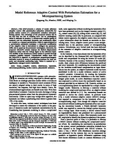
well know and predictable, a preset path can be used. But most environments are dynamic and unknown. Here we utilize a continuous collision algorithm as presented in references [9], [10] and [11]. While this technique can be applied at both the cluster level and the individual robot level, in this work it is only applied at the robot level. C. The ASVs The design of the vessels emphasizes versatility, ease of operation, and low cost in all design segments. The use of common bus architecture across all Robotic Systems Lab robotic vehicles enables a rapidly reproducible control system capable of transparently controlling multiple platforms, including several different types of land rovers, an aerial vehicle, and two different types of ASVs. Off the shelf parts, like a readily available kayak requiring no permanent modifications, facilitate both ease of integration and quick replacement if the need arises. Minor upgrades and modifications have been made to the ASVs including a new deployment and transportation system as well as structural upgrades decreasing the required time for setup and deployment. The details of the control hardware, protocol, propulsion, and power subsystems can be found in previous publications such as [2]. II. THE CONTROLLER The motivation of this research is to promote the simple specification and monitoring of the motion of a mobile, multi-robot system. Our vision is to enable automated, formalized execution of operator directives based on information such as “Drive North at 5 m/sec in a side-byside line with a 25 m separation,” or “Translate and rotate based on joystick inputs while decreasing the lateral size of the formation.” In general, enabling features of a system providing such conceptual level specification include flexibility in the choice of specifications made to define the desired motion and the judicious selection of default values appropriate to the system design and application. A. Cluster Space State Variables Fig. 1 depicts the reference frames for the planar 3-ASV problem. To complement the sensor data used in experimentation, the global frame conventions were selected as follows: YG points north, XG points east. The cluster frame is located at (X0, Y0) and its orientation is given by θ1 which is the angle about robot 0 from YG to the location of robot 1 as shown below. Robots 1, 2 and 3 are defined by a radial distances, R1, R2 and R3 from robot 0. Robots 2 and 3 are each also defined by a fence spacing from robot 1 given as F2 and F3. Further expansion would be added in an even-odd pattern with robot 4 and 5 referenced radially from robot 0. Robot 4 would be fence spaced from robot 2, while robot 5 would be fence spaced from robot 3.
Fig. 1. Cluster and robot
B. Kinematic Equations The forward position kinematics are a set of equations the allow the transformation from robot variables, X0, Y0, φ0, X1, Y1, φ1, X2, Y2, φ2, X3, Y3, and φ3, to cluster variables, Xbrc, Ybrc, φbrc, R1, θ1, φ1c, R2, F2, φ2c, R3, F3, and φ3c. The inverse kinematics allow the cluster variables to be changed back into the robot variables. The equations for the forward kinematics can be seen in (1-6). And the inverse are shown in (7-12). Note that the equations for X0, Y0, φ0, φ1, φ2, and φ3 trivially correspond directly to their respective cluster variables for the selected cluster definition and are not included. R1=((X1-X0)2+(Y1-Y0)2)1/2
(1)
θ1=Atan2((X1-X0),(Y1-Y0))
(2)
R2=((X2-X0)2+(Y2-Y0)2)1/2
(3)
F2=((X2-X1)2+(Y2-Y1)2)1/2
(4)
R3=((X3-X0)2+(Y3-Y0)2)1/2
(5)
F3=((X3-X1)2+(Y3-Y1)2)1/2
(6)
X1=Xbrc+R1* Sin(θ1)
(7)
Y1=Ybrc+R1* Cos(θ1)
(8)
X2=Xbrc+R2* Sin(θ1+acos((R12+ R22- F22)/2* R1* R2))
(9)
Y2=Ybrc+R2* Cos(θ1+acos((R12+ R22- F22)/2* R1* R2)) (10) X3=Xbrc+R3* Sin(θ1+acos((R12+ R32- F32)/2* R1* R3))
(11)
Y3=Ybrc+R3* Cos(θ1+acos((R12+ R32- F32)/2* R1* R3)) (12)
C. Control Framework Fig. 2 presents the control architecture for trajectory based cluster space control of an n-robot system. A cluster level PID controller compares cluster position and velocity with desired trajectory values and outputs cluster commanded velocities, which are translated into individual ASV velocities through the inverse Jacobian. Data from the ASVs are converted to cluster space information through the forward kinematics and Jacobian and fed back into the controller. The non-holonomic constraint given by the differential drive motion of the ASVs effectively reduces each ASV from three degrees of freedom down to two. For the cluster of ASVs it becomes a six DOF system. As a consequence, an inner-loop ASV level heading control is needed on each ASV and the cluster space controller does not regulate the cluster parameters corresponding to the yaw orientation of the ASV relative to the cluster.
Fig. 2. Cluster Space Control Architecture for an n-Robot system
D. Obstacle Avoidance
automation of different applications. It can minimize the number of cluster variables needing to be directly controlled by the pilot or cluster supervisor. For this work it is used to reduce the number of variables specified from six down to three. III. SIMULATION AND RESULTS The main objective of this research was to validate the cluster space control architecture for a multi-ASV System while utilizing obstacle avoidance and to determine the viability of a new shielding technique applied in application space. Two main cases were run, basic shielding, and shielding with threat detection. A. Basic Shielding In the case of the basic shielding technique we are applying it to a main vessel deploying an ROV. Using the application space, the operator can set the standard shield radius, the maximum approach and the minimum fence spacing. In this first instance the standard shield radius is set to 17m, the minimum fence spacing and approach are disregarded as there is no threat. When there is no threat, the application space automatically sets the ASVs into an evenly spaced formation and rotates them about the boat and ROV centroid as shown in Fig. 3. With the random selection of the ASV starting points the initialization might cause them to be on a path that would make them collide with the boat or cross over the ROV. The obstacle avoidance algorithm successfully pushes each of the ASVs away from the boat and rov, avoiding any potential collisions.
Different approaches can be used to avoid collisions with obstacles or other robots in the formation depending on the nature of the task. When keeping the formation at all times is not a priority a robot level obstacle avoidance algorithm can be utilized. In this case, the ASVs negotiate obstacles in an independent fashion, momentary breaking away from the formation. Once the obstacle has been avoided the ASV will return to the cluster. This algorithm is input the position of the obstacle and feeds an offset after the cluster space controller as shown in Fig. 2. For each ASV, the detection radius and the avoidance potential can be set. The function as shown in [8] has a zero value outside the detection radius, and an infinite at the minimum circle enveloping the ASV. Typically circles are used, but for a non-circular shape, like a ship, an elongated oval can be defined to better model the outer edge of the vessel. E. Application Space and Shielding Application Space is an additional layer between the cluster space controller and the user interface. It is a more versatile way to modify the interaction of the user with the cluster space variables. The application space can be used to implement conditional and behavioral modes needed for
Fig. 3. Standard shielding, no threat.
The response of each parameter in the cluster space for the run shown in Fig. 3. are shown in Fig. 4. It can be seen from the graphs that the controller is capable of compensating for dynamics added by the ASVs even when starting from random locations.
A. Shielding with Threat Detection An overhead view of the second case, shielding with threat detection, is shown in Fig. 5, and the individual components of the cluster space variables are shown in Fig. 6. In this instance the application space is used to set the standard radius is to 17m, the maximum approach is 50m, and the minimum fence spacing is set to 5m. The overhead view in Fig. 5 is broken down into five time segments, each showing a different interaction with the threat and the boat and ROV cluster. At step 1 the ASVs are in a standard formation around the boat and ROV centroid. The threat is identified and they begin to rotate to a position in between the threat and the boat and ROV centroid. At step 2 the threat is continuing to approach. The ASVs are still tracking along the heading pointing at the threat. They have come further out and are narrowing the fence spacing between them. At step 3 the threat has reached the max approach and the ASV have set the fence spacing to the minimum value as set in the application space. It can also be seen that the obstacle avoidance is playing a part, with ASV 1 backing away to avoid a collision with the threat. At step 4 the threat has begun to stand down and the ASVs reduce the radius and increase the fence spacing while still staying between the threat and the boat and the ROV. At step 5 the threat is outside the visible range. The ASVs have fully disengaged and resumed the basic shield rotating around the boat and ROV.
Fig. 5. Overhead view of shielding technique with threat detection. Fig. 4. Basic shielding cluster variables
successfully implemented and displayed. As a result, the three-robot cluster space definition and control architecture was validated and basic functionality was proven for this application. Our ongoing and future work in this field is focused on enhancing motion control performance, increasing the number and variety of vehicles, and integrating the motioncontrol oriented cluster space controller with application layer controllers. We believe that this will lead to enhanced performance for real-world marine applications as well as cost-effective improvements in operating such systems through the reduction of the operator/robot ratio required to control such systems. Field experimental tests of the simulations presented here are scheduled for the next few months. ACKNOWLEDGMENTS The authors gratefully acknowledge the contribution of Ryan Ishizu, Ray Chindaphorn, Tran To, Brian Tully, Mike Rasay, and Matthew Kalkbrenner. REFERENCES [1]
Fig. 6. Shielding with threat detection cluster space variable
IV.CONCLUSION The cluster space state representation of mobile multirobot systems was applied and evaluated for a three-ASV system as a means of specifying and controlling the desired mobility characteristics for surface vessels. Both obstacle avoidance algorithms and shielding techniques were
D. Siljak, Decentralized Control of Complex Systems, Academic 1991. [2] P. Mahacek, et. al. Cluster Space Control of Autonomous Surface Vessels. Marine Technology Society Journal, Volume 43, Number 1, pp 13-20. [3] C. Kitts, and I. Mas, “Cluster Space Specification and Control of Mobile Multi-Robot Systems,” Mechatronics, IEEE/ASME Transactions on, vol. 14, no.2, pp. 207-218, April 2009. [4] R. Ishizu, The Design, Simulation and Implementation of MultiRobot Collaborative Control from Cluster Perspective. Advisor: C. Kitts, Santa Clara Univ. Master of Science in Elec. Eng. Thesis, Dec 2005. [5] P. Connolley, Design and Implementation of a Cluster Space Trajectory Controller for Multiple Holonomic Robots. Advisor: C. Kitts, Santa Clara Univ. Master of Science in Mech. Eng. Thesis, June 2006. [6] T. To, Automated Cluster Space Trajectory Control of Two NonHolonomic Robots. Advisor: C. Kitts, Santa Clara Univ. Master of Science in Computer Eng. Thesis, June 2006. [7] M. Kalkbrenner, Design and Implementation of a Cluster Space Human Interface Controller,. . . Advisor: C. Kitts. Santa Clara Univ. Master of Science in Mech. Eng. Thesis, June 2006. [8] P. Chindaphorn, Cluster Space Obstacle Avoidance for Two NonHolonomic Robots. Advisor: C. Kitts. Santa Clara University Master of Science in Computer Engineering Thesis, June 2006. [9] I. Mas, O. Petrovic, and C. Kitts, “Cluster space specification and control of a 3-robot mobile system,” Robotics and Automation, 2008. ICRA 2008. IEEE International Conference on, pp. 3763–3768, May 2008. [10] I. Mas, Obstacle Avoidance Policies for Cluster Space Control of Non-Holonomic Multi-Robot Systems. IEEE [11] C. Kitts, K. Stanhouse, and P. Chindaphorn, “Cluster space collision avoidance for mobile two-robot systems,” Intelligent Robots and Systems. IEEE/RSJ International Conference on, Oct 2009.