ADAPTIVE DIRECTIONAL WAVELET TRANSFORM USING PRE-DIRECTIONAL FILTERING Yuichi Tanaka1 , Madoka Hasegawa1 , Shigeo Kato1 , Masaaki Ikehara2 , and Truong Q. Nguyen3 1: IS Dept., Utsunomiya University: Utsunomiya, Tochigi, 321-8585 Japan email: {tanaka, madoka, kato}@is.utsunomiya-u.ac.jp 2: EEE Dept., Keio University: Yokohama, Kanagawa, 223-8522 Japan email:
[email protected] 3. ECE Dept., University of California, San Diego: La Jolla, CA 92093-0407 USA email:
[email protected] ABSTRACT This paper proposes a computationally efficient approach of adaptive directional wavelet transform (AD WT). The AD WT is based on lifting implementation of WT, and it is able to transform an image along diagonal orientations as well as traditional horizontal and vertical directions. The AD WT sacrifices computational speed for its good image coding performance. We present an alternative method to find the best transform directions by pre-directional filterings for the AD WT. The proposed direction calculation method shows very comparable image coding performance to the conventional one, whereas its computational cost is relatively very low.
Fig. 1. Directional lifting steps for AD WT. (Left) prediction step. (Right) updating step.
Index Terms— Adaptive directional wavelet transform, wavelet transform, directional lifting, image coding 1. INTRODUCTION
the best transform directions. In the experimental results, its performance is very comparable to the previously proposed AD WTs and the calculation cost has been reduced.
Adaptive directional wavelet transform (AD WT) using lifting implementation [1, 2, 3] is a recently developed scheme to realize effective multiresolution image representation (MIR). It mainly focuses on concentrating energy in an image into the LL subband of a quad-tree MIR by using transformations along diagonal orientations as well as the traditional horizontal and vertical orientations. Since edges, i.e., regions containing high-frequency, usually existing diagonal orientations, the adaptive filterings along edges/lines could reduce energy in high-frequency subbands. Although a number of adaptive transforms, which classify and decompose images into blocks with similar directional features and process each decomposed block depending on directional information, have been proposed [4, 5, 6, 7], MIR using the AD WT is compatible with one using the traditional separable 2-D WT, and thus, efficient quad-tree encoders such as SPIHT [8] can be used. In image coding, the AD WT outperforms the separable WT especially for images with rich textures. The conventional AD WTs determine the transform direction for each pixel or block by transforming along all possible direction candidates. The process requires several transformations in each pixel, hence the computational cost is much higher than that of the traditional 2-D WT. It is a trade-off between the compression performance and computational cost, however, the cost needs to be reduced. In this paper, we present an alternative method to find the best transform direction for the AD WTs. It is based on prefilterings of the original image by the directional WT for two fixed directions, and the obtained subbands are used as reference frames to find
978-1-4244-5654-3/09/$26.00 ©2009 IEEE
2. AD WT AD WTs divide an image into a set of small blocks. Each block is assumed to have one transform direction and it is transformed by the directional lifting. The directional lifting steps are illustrated in Fig. 1. Let x(m, n) denote the pixel value at (m, n). A prediction step for a direction θ with the vertical downsampling [2] is represented as h(m, 2n + 1) = x(m, 2n + 1) − P (m, 2n) (1) where h(m, 2n + 1) represents a highpass branch of the directional lifting step and P (m, 2n) = pi (x(m − tan θ, 2(n − l)) + x(m + tan θ, 2(n + l + 1))) (2) in which pi is a coefficient for this prediction step and l is a nonnegative integer. An updating step is given by l(m, 2n) = x(m, 2n) + U (m, 2n + 1)
(3)
where l(m, 2n) represents a lowpass branch and U (m, 2n + 1) = ui (h(m − tan θ, 2(n − l) − 1) + h(m + tan θ, 2(n − l) + 1)),
1
(4)
ICIP 2009
Adaptive Directional WT Original image
Transformed image Direction Data Direction Calculation
Reference Frames
High-frequency subband 1
High-frequency subband 2 Directional highpass WTs
Fig. 4. DF-AD WT framework.
Fig. 2. Transform direction of the conventional AD WT. (a) directions for each block (enlarged). (b) an optimal tree of transform directions. (1, 3)
Downsampling Direction
(1, 2) Interpolation required (0, 1) (1, 1)
Row to be transformed
(-1, 1)
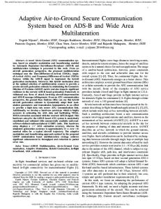
Fig. 5. Subbands after transformed by the prefilterings. (Top) reference frame 1. (Bottom) reference frame 2.
(-1, 2) Interpolation required (-1, 3)
3. DIRECTIONAL FILTERING-BASED AD WT
Fig. 3. Directions for the directional WT. In this section, the detailed description of the directional filteringbased AD WT (DF-AD WT) is presented. Its framework of the analysis side is shown in Fig. 4. The directional WTs for two fixed directions reduce calculation costs of the transform directions by using the obtained subbands as reference frames. Moreover, they also contribute to having the same direction data in neighboring regions with a similar directional feature.
in which ui is an updating coefficient. Clearly these lifting steps are perfect reconstruction and can be cascaded with other lifting steps similar to the separable WTs. Usually, the AD WT determines a transform direction for a block to choose the direction yielding the lowest high-frequency energy. Fig. 2(a) shows directions for Barbara image with the block size 8 × 8. It is clearly noticeable that neighboring blocks often contain different directions even if the region (macroblock) has similar feature. Since the direction information has to be losslessly transmitted and is difficult to shrink its size as-is, the AD WTs construct the optimal tree for the transform directions taking into account of distortions in high-frequency subbands and the amount of bits to represent transform direction(s) as Lagrangian cost function. For example, an optimal tree is shown in Fig. 2(b). Pixels within a white square has been determined to have the same curve. The tree and direction data are finally coded. However, the tree calculation is a computationally demanding process in the AD WTs, and it should be reduced as small as possible. We define the notations of the transform directions by the AD WT as the relative pixel position from the pixel to be transformed. Some typical directions are illustrated in Fig. 3 where the direction for the separable WT is defined as (0, 1). Note that the even (odd) row to be transformed requires neighbored odd (even) rows in each lifting step for perfect reconstruction. Therefore, the directions (1, 2), (-1, 2), etc. cannot be transformed without interpolating pixels.
3.1. Directional Filtering Stage The directional highpass WTs with two fixed directions are used to yield reference frames for the following direction calculating stage. We use them to extract diagonal edges/lines. Therefore, the directional WTs are performed along directions (1, 1) and (−1, 1), whose frequency plane partitions are shown in the enclosed area by a dashed line in Fig. 4 [1]. Each square represents a frequency plane from (−π, −π) to (π, π), and blue regions indicate passbands of the filters. The directional filtering stage apply downsamplings. Finally, two reference frames which are half the height of the original image are obtained and used for the direction calculation. The obtained reference frames of Barbara image are shown in Fig. 5. Clearly the edges/lines only toward diagonal directions are extracted. The remaining zone (black regions in the figures) can be assumed to contain low-frequency information or curves along horizontal or vertical directions. Hence, the adaptive transform for the zone is not required.
2
(-1, 2) (-1, 1) (-2, 1)
(a)
X
Side direction
Fig. 7. Transform directions for DF-AD WT. O
O
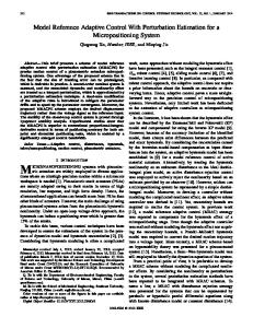
horizontally/vertically. Otherwise, the adaptive transform direction is calculated for all possible (typically, five) direction candidates. Moreover, the proposed prefilterings provide the more reliability for the selected directions in a similar texture. In the direction calculating stage of the conventional AD WT, a selected candidate is expected to fit a diagonal line in a block. However, the selected direction could be different from the accurate curve. The problem is explained by Fig. 6(b) for the direction candidate (1, 3). The red regions show the passband of the (1, 3) directional lowpass filter. The (1, 3) is expected to fit the diagonal line shown in the solid arrow which corresponds to the highest frequency “O” in the frequency plane. However, the direction (−1, 1) shown as the dashed arrow (corresponding to “X”) could be also extracted to the low-frequency subband. As a result, the selected direction in the conventional AD WT may indicate a different direction from the actual one. It causes that neighboring blocks with a similar texture does not have the same transform directions. In the viewpoint of the amount of the transform direction data to be encoded, those blocks should be classified to have the same direction. As previously mentioned, the AD WT solves the problem by merging blocks using Lagrangian cost function, whereas the DF-AD WTs utilize the band limitation. Its example is shown in Fig. 6(c). The side direction “X” has been eliminated by the prefiltering (−1, 1) before the direction calculation stage and the remaining edges/lines are almost from the bottom left to the top right. Therefore, the selected direction (1, 3) in the DF-AD WT is considered to fit the actual edges/lines. The transform directions in the DF-AD WT can be well unified without constructing a tree for the transform directions, and thus, the prefilterings can reduce the tree calculation cost. The output of the transform directions for the vertical downsampling overwritten on the original Barbara image is shown in Fig. 7. The similar regions are well classified and have the same direction data. Comparing with Fig. 2(a) for the conventional AD WT, our directional filtering-based method presents a simple representation for the directions.
O
O X Expected curve (b)
Expected curve (c)
Fig. 6. The search range elimination by the directional prefilterings of the DF-AD WT and the expected and side directions in the direction calculating stage. (a) search range elimination by predirectional filtering along (−1, 1). The candidates in a sector is eliminated in the direction calculating stage. (b) passband of the (1, 3) lowpass filter in the direction calculating stage of the conventional AD WT. The solid arrow and “O” denote the expected curve, whereas the dashed one and “X” represent the side direction. (c) direction search range after prefiltering along (−1, 1) (corresponding to subband 2 in Fig. 4).
3.2. Direction Calculating Stage The obtained two reference frames are used to determine the transform direction for the AD WT. To reduce the calculation cost, the directions are decided in a block-wise manner; first, the reference frames are partitioned into blocks with size N/2 × N , and then the directions are calculated for each N × N block in the corresponding position of the original image. Each reference frame indicates that the original block has a few direction candidates. The blue regions in Fig. 6(a) show the highpass subband of the directional filtering along (−1, 1). The filtering omits the candidates from the top left to the bottom right; (−2, 1), (−1, 1) and (−1, 2). In other words, the reference frame after the filtering along (−1, 1) has a few candidates for the other diagonal directions from the bottom left to the top right, for example, (1, 1), (2, 1) and (1, 3). In a typical case, the conventional AD WT requires nine transforms to determine a transform direction [1, 2]. One transform is for the traditional vertical direction, whereas the remaining eight ones correspond to the diagonal directions. The DF-AD WT, simply, reduces four diagonal candidates by prefiltering. Furthermore, many blocks in the reference frames contain almost dark pixels where adaptive transforms are not required since the block in the original image can be assumed not to include diagonal edges/lines. We recognize those blocks by using sum of absolute values (SAV) for a block. If the SAV of a block in the reference frames is less than a threshold T , it is not sent to the direction calculation. The corresponding block in the original image is transformed
4. IMAGE CODING PERFORMANCE Image coding results are compared in this section to validate the DFAD WT. Three WTs, the separable WT, conventional AD WT and DF-AD WT, are adopted. All transforms are set to have 5-level decomposition and used SPIHT as the image encoder. For both of the AD WTs, adaptive transform is used for the vertical downsamplings of the first 2 levels. Moreover, additional bits for the AD WTs are included in the target bitrates. The number of filterings for the DF-AD WT is clearly fewer than
3
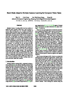
Fig. 8. Reconstructed Barbara. The images are cropped for better visualization. (Left) 9/7 WT (26.02 dB). (Middle) conventional WT (27.53 dB). (Right) DF-AD WT (27.48 dB).
between the AD WTs are very similar.
Table 1. PSNR Comparison for Various Bitrates Transform Image bpp 9/7 WT Conv. AD WT DF-AD WT 0.1 23.72 24.75 24.68 0.3 27.66 29.29 29.25 Barbara 0.5 30.64 31.95 31.88 1 35.72 36.52 36.44 0.1 29.18 29.09 28.98 0.3 34.08 34.22 34.13 Lena 0.5 36.54 36.63 36.58 1 39.78 39.79 39.76 0.1 25.81 25.77 25.72 0.3 31.22 31.36 31.33 Monarch 0.5 34.69 34.86 34.82 1 40.78 40.90 40.88
5. CONCLUSIONS In this paper, we proposed a transform direction determining method for the AD WTs. It is regarded as the prefilterings by the directional WT for two fixed directions and the obtained subbands are used as reference frames for the direction calculation of the AD WT. The proposed framework requires fewer filtering operations than the conventional full search AD WTs. However, both of the AD WTs show very similar performance in image coding and outperform the separable WT especially for the image with rich textures. Our future work includes to apply the DF-AD WTs for wavelet-based video coding to exploit the effectiveness of the computational complexity. 6. REFERENCES [1] C.-L. Chang and B. Girod, “Direction-adaptive discrete wavelet transform for image compression,” IEEE Trans. Image Process., vol. 16, no. 5, pp. 1289–1302, 2007.
that of the conventional AD WT. In the comparison of the number of operations, our DF-AD WT requires fewer operations than the conventional one since calculating SAV in a block simply needs one addition/pixel. Furthermore, the execution time is an intuitive comparison for the computational complexity. We set the same conditions for both AD WTs; 16×16 minimum block size, all MATLAB codes, and Windows Vista SP1 with Pentium Core2 Duo E8500 (3.16 GHz) CPU and 2 GB RAM. It takes around 1.8–1.9 seconds for the conventional AD WT, whereas 0.5–0.8 seconds for the DF-AD WT. Naturally, the separable (nonadaptive) WT is significantly faster (about 0.12 seconds) than these two transforms. However, the proposed method is faster with larger block size. For example, the DF-AD WT takes 0.3 seconds of the execution time when the block size is 32 × 32 with 0.1 dB decrease of PSNR. The PSNR comparison for various bitrates are shown in Table 1. For Barbara image, both of the AD WTs outperform the separable WT since the image contains a lot of rich textures. The conventional AD WTs obtained slightly higher PSNR (less than 0.1 dB) than the DF-AD WT. For Lena image, all of three transforms show similar performance. In low bitrates, the conventional AD WT is slightly worse than the separable WT since they have the extra information for the transform directions. The adaptive transforms gain marginal improvements for Monarch image since the image has an intermediate feature between Barbara and Lena images in frequency domain. The reconstructed Barbara images for 0.2 bpp are shown in Fig. 8. Clearly the AD WTs preserve high-frequency information in the image at low bitrate. Moreover the reconstructed image qualities
[2] W. Ding, F. Wu, X. Wu, S. Li, and H. Li, “Adaptive directional lifting-based wavelet transform for image coding,” IEEE Trans. Image Process., vol. 16, no. 2, pp. 416–427, 2007. [3] D. Wang, L. Zhang, A. Vincent, and F. Speranza, “Curved wavelet transform for image coding,” IEEE Trans. Image Process., vol. 15, no. 8, pp. 2413–2421, 2006. [4] V. Velisavljevi´c, B. Beferull-Lozano, M. Vetterli, and P. L. Dragotti, “Directionlets: Anisotropic multi-directional representation with separable filtering,” IEEE Trans. Image Process., vol. 15, no. 7, pp. 1916–1933, 2006. [5] D. L. Donoho, “Wedgelets: Nearly minimax estimation of edges,” Ann. Statist, vol. 27, no. 3, pp. 859–897, 1999. [6] E. Le Pennec and S. Mallat, “Sparse geometric image representations with bandelets,” IEEE Trans. Image Process., vol. 14, no. 4, pp. 423–438, 2005. [7] E. Cand`es and D. L. Donoho, “Ridgelets: a key to higherdimensional intermittency?,” Phil. Trans. R. Soc. Lond. A., pp. 2495–2509, 1999. [8] A. Said and W. A. Pearlman, “A new, fast, and efficient image codec based on set partitioning in hierarchical trees,” IEEE Trans. Circuits Syst. Video Technol., vol. 6, no. 3, pp. 243–250, 1996.
4