2008 Congress on Image and Signal Processing
A Two-Stage Contrast Enhancement Algorithm for Digital Images Shen-Chuan Tai, Nai-Ching Wang, Yi-Ying Chang, Yen-Cheng Lu Department of Electrical Engineering, National Cheng Kung University
[email protected], {wnc96m, cyy93d, lyc94m}@dcmc.ee.ncku.edu.tw, further used logarithmic mapping function to implement tone mapping, and Eric [7] also used a logarithm like function in his video enhancement algorithm. The difference between logarithmic curves and gamma curves is that logarithmic curves obey the Weber-Fechner law of just noticeable difference (JND) response in human vision [6]. For HDRI compression, Tumblin and Turk [8] proposed a method based on artist's point of view. They divided the whole image into separate detail level through a method based on anisotropic diffusion. Ward Larson and Rushimeier [9] presented a tone reproduction operator capable of preserving visibility in high dynamic range scenes. Their method introduced a new histogram adjustment technique, based on the population of local adaptation luminance in a scene. The method also incorporated models for human contrast sensitivity, glare, spatial acuity, and color sensitivity to reproduce experience of human vision. R. Fattal et al. [10] manipulated the gradient field of the luminance image by attenuating the magnitudes of large gradients. They constructed a Gaussian pyramid to identify large gradients at various scales and attenuate their magnitudes while keeping their direction unaltered. In this paper, we propose an algorithm to enhance local contrast of an image which can be an LDRI or an HDRI. In section 2 we introduce a method to enhance local contrast of LDRI and HDRI by simultaneously using logarithmic curve and tone-mapping. Experimental results comparing our method with several other methods are shown in section 3. Section 4 concludes this paper.
Abstract Studies of contrast sensitivity of the human eyes show that logarithmic curves obey the Weber-Fechner law of just noticeable difference response in human perception. In this paper, we propose a local contrast enhancement algorithm with logarithm-based curves for both high dynamic and low dynamic images and this algorithm can adaptively change the curvature with local information. We also define two parameters to decide the level of contrast enhancement in the tone mapping procedure. For halo artifact which is suffered from local operator, a two-stage procedure is designed to solve the problem. We present experimental results to show performance of our algorithm compared with other existing methods.
1. Introduction Digital Cameras that gradually replace conventional cameras store photographs in digital format. As a result, captured images can be more easily processed. Contrast enhancement plays a very important role in increasing visual quality of an image [1]-[3]. For this reason, a lot of contrast enhancement techniques have been proposed but most of them are proposed to process low dynamic range image (LDRI) and today’s digital cameras have the ability to capture high dynamic range image (HDRI) with about 200% to 600% luminance level, while most of the display devices have low dynamic range with only about 110% luminance level [4]. Consequently, a new contrast enhancement method for both LDRI and HDRI is required. A logarithmic curve is usually employed in contrast enhancement for the less complexity and more acceptable results than others. Stockham [5] first showed the advantages of logarithmic curves, Drago [6]
978-0-7695-3119-9/08 $25.00 © 2008 IEEE DOI 10.1109/CISP.2008.400
2. Proposed Algorithm To enhance contrast of an image, Eric and Stockham's suggestion, a simple form of logarithmic curve is used in our method and can be shown as
256
v ( x, y ) =
log( w( x, y ) × ( β − 1) + 1) log( β )
(1)
where v(x,y) is the luminance level after enhancement, w(x,y) is the luminance level before enhancement and β is the value that controls logarithmic curve. The curve in (1) is for global contrast enhancement because all pixels share the same β value and we will introduce its local version which can show us more details. In the local version, we build a map called beta map which contains the β value for each pixel. There are two main steps to build a beta map. Before the two main steps, we need edge information. We will make use of sobel filter to get the edge information. In the first step, every pixel is classified into two categories which are edge and non-edge. The β value of edge pixels is set to be undefined and will be decided in the second step. For each non-edge pixels, we set a mask around the pixel and calculate the mean value of pixels within the mask. In order to prevent halo artifacts not all pixels in the mask are taken into account and a threshold is set to decide the valid pixels. If the luminance difference between a pixel and the center pixel is greater than the threshold, this pixel is not valid and will not be taken into account in computation of the mean. The β value for each pixel will be computed by the following equation. w( x, y) − mean ⎧ +2 ⎪10 × w( x, y) ⎪⎪ β =⎨ 2 ⎪ undefine ⎪ ⎪⎩
, w( x, y) ≥ mean and Sobel ( x, y) < th
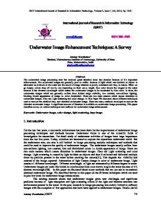
Fig. 1 The value of β versus luminance with different local means.
of the center pixel. We calculate the luminance difference between the center pixel and its neighbors to find out the pixel luminance which is closest to the center pixel and then replace the β value of the center pixel with the β value of the pixel whose luminance is closest to the center pixel. After the second step, all β values in beta map are clearly defined. At last, we complete the local contrast enhancement by using (1) and the beta map. In (2) we set the β value of some pixels to 2, these pixels are valley part in local region. In order to enhance the valley region in the image, we reverse the luminance of the image by subtracting the original luminance from maximum luminance and apply first pass and second pass to the inverse image again. By reversing the image, the valley part has good possibility of becoming the peak part in the image then we can enhance these pixels correctly. In order to take HDRI into account, a tone mapping algorithm for compressing the dynamic range is required. Monobe [4] proposed a tone mapping algorithm with preserving local contrast, and in our algorithm his algorithm was slightly modified to satisfy our requirement. The following equations (3) and (4) demonstrate the core concept presented by Monobe. v( x, y) = Tone(w( x, y)) × E(w( x, y), wavg ( x, y)) (3)
(2)
, w( x, y) < mean and Sobel ( x, y) < th , otherwise
where w(x,y) is the luminance level before enhancement, mean is the average value of valid pixels within the given mask, Sobel(x,y) stands for sobel filter applied at (x,y) and th is the threshold to decide whether a pixel is valid or not. Equation (2) represents a concept of human visual system (HVS). The same luminance difference in different background brightness causes dissimilar effects for human vision. Fig. 1 presents the relationship between input luminance and β value under difference local mean, and after observing the slope of each curve, it is apparent that the lower mean luminance the higher curve slope. That means the same luminance difference causes much influence under low background luminance. The second step is to find the β value of edge pixels which is undefined in the first step. If the β value of a pixel is undefined, a mask centered at the pixel is set and other pixels within the mask are called neighbors
⎛
α ⋅⎜1−
⎛ w( x, y) ⎞ E(w( x, y), wavg ( x, y)) = ⎜ ⎜ w ( x, y) ⎟⎟ ⎝ avg ⎠
⎝
w( x , y ) dTone ( w( x , y )) ⎞ ⋅ ⎟ Tone ( w( x , y )) dw( x , y ) ⎠
(4)
where w(x, y) means the input luminance, wavg(x, y) means the local average around w(x, y), Tone(w(x, y)) means the output luminance of tone mapping, and E(x, y) is the edge information which Monobe wants to preserve. The most important parameter in E(x, y) is employed to decide the contrast strength and is denoted by α, and its value which is larger than 1 will enlarge output luminance and vice versa. The criterion for determining this parameter is given in (5).
257
⎧0.25, if w( x, y ) > wavg ( x, y )
α =⎨
⎩1.75, otherwise
(5)
In order to avoid saturated luminance, if the luminance of center pixel is larger than its neighbors, α is assigned to 0.25. Otherwise α is set to 1.75 for compensating the degradation in visual contrast. In this manner, the local contrast can be preserved in the process of tone mapping, but what we need is not only preserve the contrast but also enhance the contrast. Contrast masking pointed out that for visible contrast enhancement, higher contrast objects required higher contrast increments. We apply the concept of contrast masking to modify the criterion and given in (6).
⎧1 + (1 − kweight ) × 0.75 , if w( x, y) > wavg ( x, y)
α =⎨
⎩kweight
kweight =
, otherwise
Fig. 2. The final flow chart of proposed algorithm. (6)
proposed algorithm has very good performance for both HDRIs and LDRIs. The result of HDRIs consists of images processed by the proposed algorithm and other conventional methods, such as Tumblin and Turk's [11], Ward's [9], Fattal's [10], Reinhard's [12], Ming-Long Huang’s (TSR) [13], and Li-Wei Chen’s (CLW) [14]. Fig. 3 represents that our result has better detail information than other methods do. Especially in the circular window of the roof, the stained glass window, the wood's grain and the eaves of the church. The result of LDRIs is shown in Fig. 4. The image processed by the proposed algorithm improves the gradation of the cloud and makes the grasslands brighter and provides more details.
1 exp(Sobel ( x, y))
where Sobel(x, y) is the result of sobel filter, kweight is the weight used to define whether the pixel is at the smooth region. For example, if the value of sobel filter is closing to 0, that means the pixel is at a smooth region. To prevent the occurrence of over enhancement, α is set closing to 1, then the local contrast will be only preserved rather than enhanced. On the contrary, for the pixel on the edge, α is close to 1.75 and the local contrast will get enhanced. To combine the method of tone mapping with our local contrast enhancement algorithm, the final equation is given in (7) and (8). v( x, y) =
log(Tone(w( x, y)) × (β − 1) + 1) × E (w( x, y), wavg ( x, y)) (7) log(β )
4. Conclusions
where ⎛
α ⋅⎜1−
⎛ w( x, y) ⎞ E (w( x, y), wavg ( x, y)) = ⎜ ⎜ w ( x, y) ⎟⎟ ⎝ avg ⎠
⎝
w( x , y ) dTone ( w( x , y )) ⎞ ⋅ ⎟ Tone ( w( x , y )) dw( x , y ) ⎠
In this paper we have focused our attention on local contrast enhancement algorithm for high dynamic range image and the effect of halo artifact. As a starting point, we revisited some standard tone mapping algorithm and contrast enhancement method. Next, we developed and proposed a two-stage logarithm-based local contrast enhancement algorithm for HDRIs and LDRIs. This algorithm has four advantages. First, the two-stage procedure reduced the effect of halo artifact. Second, the details in the image were enhanced during compressing the dynamic range. Third, the logarithm curvature can be adaptively change by local information. Forth, the proposed algorithm also behaved very well when the input image is an LDRI.
(8)
The final flow chart was demonstrate in Fig. 2 And the experiment results were introduced in next section.
3. Experimental results Although the HDRIs have wide range of lighting, they also need the local contrast enhancement technologies to improve the image quality. In this section, we show the different experiment results of both HDRIs and LDRIs. These results show that the
258
Tumblin
Fattal
Ward Larson
TSR
CLW
Proposed
Fig. 3. Experimental results of HDRIs Operators”, Proceedings of Pacific Graphics 2006, 14th Pacific Conference on Computer Graphics and Applications, pages 35-44. October 2006.
There are two parameters defined in our method, α and β. α is used to decide the enhancement strength of details of an image during tone mapping and β is used to decide the enhancement level of image base after tone mapping. By flexible adjusting them, the outputs can preserve lots of details.
[2] Zhou Wang, Alan Conrad Bovik, Hamid Rahim Sheikh, Eero P. Simoncelli, “'Image Quality Assessment: From Error Visibility to Structural Similarity”, IEEE Transactions on Image processing, vol. 13, no. 4, April 2004.
5. References
[3] D.Garvey, “Perceptual Strategies for Purposive Vision”,
[1] M. Cadik, M. Wimmer, L. Neumann, A. Artusi, “Image
technical note 117, AI center, SRI international 1976.
Attributes and Quality for Evaluation of Tone Mapping
259
[6] F. Drago, K. Myszkowski, T. Annen and N. Chiba, “Adaptive Logarithmic Mapping for Displaying High Contrast Scenes”, In Proceedings of eurographics 2003, 22, 3, 419-426.
[7]
Eric P. Bennett, Leonard McMillan, “Video Enhancement using Per-Pixel Virtual Exposures”, ACM Transactions on Graphics (TOG), ACM SIGGRAPH 2005 Papers SIGGRAPH '05.
[8] Tumblin and H.E. Rushmeier. “Tone Reproduction for Realistic Images”, IEEE Computer Graphics Applications, vol. 13, no.6, pp.42- 48, 1993.
the original image
and
[9] G. Ward Larson, H. Rushmeier, C. Piatko, “A Visibility Matching Tone Reproduction Operator for High Dynamic Range Scenes”, IEEE Transactions on Visualization and Computer Graphics, vol.3, no.4, 291-306, 1997.
[10] R. Fattal, D. Lischinski and M. Werman, “Gradient Domain High Dynamic Range Compression.” Transactions on Graphics, 21(3), July 2002.
ACM
[11] J. Tumblin and G. Turk, “LCIS: A boundary hierarchy for detail preserving contrast reduction.” In Siggraph 1999, Computer Graphics Proceedings, Addison Wesley Longman, Los Angeles, A. Rockwood, Ed., Annual Conference Series, 83-93.
the image enhanced by proposed method
[12] E. Reinhard, M. Stark, P. Shirley, and J .Ferwerda, “Photographic Tone Reproduction for Digital Images”, ACM trans. Graphics, vol. 21, no. 3,pp.267-276, 2002.
Fig. 4. Experimental results of LDRIs [4] Y. Monobe, H. Yamashita, T. Kurosawa, H. Kotera, “Dynamic Range Compression Preserving Local Image Contrast for Digital Video Camera”, IEEE Transactions on Consumer Electronics, Volume 51, Issue 1, Feb. 2005 Page(s):1 - 10.
[13] Ming-Long Huang, “Tone Synthesis Reproduction for Digital Image”, Workshop on Consumer Electronics and Signal Processing 2004, pp. 100-106, 2004. [14] Li-Wei Chen, “An efficient local region enhanced algorithm” 1st ILT, p.749 p.756
[5] T. G. Stockham, “Image Processing in the Context of a Visual Model”, Proceedings of the IEEE, July 1972 Volume: 60, Issue: 7 On page(s): 828- 842 ISSN: 0018-9219.
260