1
DEVELOPMENT OF ECONOMICAL MODULAR EXPERIMENTAL UNMANNED UNDERWATER VEHICLE DESIGN AND FEASIBILITY STUDY IS COOPERATIVE ROBOTICS Eduardo Moreno Undergraduate Student Department of Mechanical Engineering University of Arizona Tucson, AZ 85719 USA computers to execute intricate previously programmed missions. Abstract—We propose a novel, economical, and modular underwater robot that can self-reconfigure by arranging itself in geometric shapes. Applications for this robot include underwater exploration, construction, and repair. Our current prototype is a single module which contains the basic structure for the modules to come. This robot functions as a test-bed for software and hardware implementation as well as cooperative robotics control theories. We describe the module design and discuss the rationale behind it. The structure, propulsion, and camera system are addressed in detail. Future publications will present experimental results on vehicle dynamics and control capabilities. Index Terms—Modular robot, underwater robot, cooperative robotics, dynamics, stability.
I. INTRODUCTION Very recently, we witnessed the British Petroleum oil spill in the Gulf of Mexico, a large man-made disaster that has devastated the gulf coast. The severe lack of underwater technologies necessary to stop the disaster became apparent to the world. Most deep sea operations have complex issues that are difficult to solve and entail heavy risks. Underwater robots are the number one tool for the job. Underwater robots are instrument platforms used to operate in underwater environments. Two primary categories of underwater robots exist: Remotely operated vehicle (ROV) and autonomous underwater vehicle (AUV). The major difference between the ROV and the AUV is that the ROV is controlled by an individual from a remote location with the aid of a cable to transmit data and power. An AUV is controlled without human intervention with the use of on-board computers and batteries or fuel cells as a source of power. AUVs are usually employed for long term exploratory missions. Since AUVs are independent of human control, they are more complex and are equipped with sensors and onboard
Underwater robots are currently being employed to perform an array of tasks that range from scientific and environmental data gathering to inspection and assembly of submarine facilities and equipment. ROVs are usually used by the oil industry to build underwater pipelines and off-shore platforms. They are also used to monitor water pollution. Underwater robotic research is becoming more popular due to the growing need for access to underwater environments at a low cost. The main issues contributing to the high cost of these systems are necessity for specialized tools rated for deep-water usage and the customization that goes in designing and building the control systems. Underwater robot technology has been increasingly researched in the past years and has a bright future ahead. Commercial underwater robots will help people in ocean research, rescue operations, and monitoring for marine pollutants. The design of such robots are currently being considered for space exploration missions to Jupiter’s moon, Europa, which is said to posses water and possibly alien life. Underwater robots will continue to be developed to help humans explore the remaining 70% of the earth that is covered by water. After engaging in the underwater robot development process and weighing several conceptual designs, a concept for an economical autonomous vehicle was conceived and adopted for this research. This paper discusses phase one of the development of an AUV module which will form part of a cooperative robotic system. The research focuses on the design rational and fabrication of an underwater robot. The paper also presents a brief summary of the entire scope of the project. II. COOPERATIVE ROBOTIC CONCEPT A modular approach to underwater robotic systems has great potential for reducing costs, increasing long-term reliability, and providing the means for rapid repair and system upgradability. Such an unmanned underwater network would consist of an assembly of a number of modules, each designed for specific tasks such as gripping, navigation, temperature reading, specimen storage, etc. Each module would be stand-
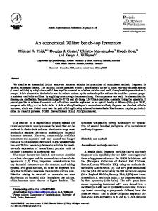
2 alone meaning that it could swim and navigate independently. The modules within the system would share data to aid in performing cooperative jobs. Each module has the shape of an isosceles triangle if viewed from the top. This shape allows for the creating of more complex geometric shapes. We can see from Figure 1.0 how six modules comprise one bigger circular entity. One can consider a module in this case like a slice of a pizza, where the pizza is comprised of many slices. The advantages of modules connecting to form a larger structure is that a larger structure is more stable in the water, a larger structure has more thrusters and therefore it can retrieve and manipulate larger loads, and a larger structure optimizes energy usage by reducing the amount of thrusters that need to be power-on when moving.
unaddressed, control challenges. These challenges result from the dynamic interactions between modules, the changing inertial properties, structural conformity, and sensor and actuator redundancy. The control of formation for modular robotic systems has been well studied [5, 7, 8], as well as the control of underwater vehicles with six degrees of freedom in navigation and docking [4, 6, 9]. Geometric formation of smaller underwater robotic modules could distribute the functionality of a single large underwater robot over a set of cooperative, smaller, less expensive robots which would navigate without physically touching each other. Work in this field has focused on modeling, coordination and control, simulation, and autonomous formation configurations [8, 11]. While the modular robots present many advantages to single-bodied, more complex robots, the control of these robots is very challenging due to difficulties in communication among modules in subsea environments and in synchronizing modules in a three-dimensional environment.
Since each module will be able to navigate independently, the structure could break up at any time and each module could set off to perform a task on its own.
Much research has been done in the fields of control methods for modular robots [7, 8, 10, 13]. This modular underwater concept will address the advantages of a semi-modular control configuration where a main system can perform tasks when modules are physically united or the modules can split off into individual and independent more simple modules when necessary. When modules are travelling together they are more stable, have more power, and form a more complete single vehicle.
III. RELATED WORK
IV. RESEARCH SCOPE
In recent years, there has been considerable interest in the design and control of multiple cooperative robotic vehicles [7, 12, 14] with the vision that multiple robotic vehicles will perform tasks faster and more efficiently than a single vehicle. During an exploratory mission, modular vehicles share information about their current location and the areas that they have already visited [9]. Moreover, the possibility of mass producing simple modules rather than individually crafting unique and complex vehicles offers great potential for design and production savings [10]. The modular approach also provides redundancy. The ability to completely replace failed modules will greatly decrease probability of failure [2, 8]. Furthermore, the tasks to achieve may be too complex for one single robot, whereas they can be more effectively done by multiple robots [1]. In this concept, system assembly would take place underwater. Hence, each module must carry sufficient thrusters and sensors to permit full mobility in control and docking [3]. These multiple thrusters and sensors would give the assembled system redundancy and again a level of robustness and flexibility.
This research paper is an attempt to describe a system which demonstrates through physical implementation the feasibility of a modular autonomous underwater robot network. While the idea of such robots has recently been conceptualized, its physical implementation is still in a prototype stage.
Consequently, modular underwater robotics systems have the potential to be simultaneously less expensive and more responsive, adaptable, and robust to the failure of one of the modules. With the stated benefits come significant, and largely
With the intension to contribute to the field of modular robotics, one robotic experimental underwater robotic module has been developed as a platform for testing methodologies in cooperative robotics. This section presents the steps and
Figure 1.0: Modular Robot Geometric Structure
This paper will focus on the first stage of the development of an underwater network which consists primarily of the identification of the mission and how it will be accomplished. To this end, the design of a modular underwater vehicle will be presented and discussed. The methods to coordinate the control and the dynamics of the modules will be reserved for future research. Eventually we hope to arrive at the level where we can effectively use or create theories in cooperative modular robotics and implement optimization processes to allow for a robust and sea-worthy underwater robotic design. V. METHODOLOGY
3 thought process that were considered in developing this robot. As depicted in Figure 2.0, the process used for the design of this robot is outlined in a flow chart. Further analysis on the steps will be discussed up until Step E. The remaining three steps are beyond the scope of this paper.
required, and the size and weight of the sensors (payload) the vehicle would be carrying. The vehicle would be primarily used in shallow waters such as pools and lacks, hence a maximum depth of 25 feet was chosen as the result in a pressure of 10.83 lbs/in2. In order to allow for the vehicle to maneuver around small bodies of water and around submerged structures the vehicle size was limited to 2ft3. B. Performance Parameters and Cost Goals The major design requirements selected when designing the module include ease-of-operation, including setup and maintenance, robustness, having a sturdy design that can stand up to harsh environments, modularity, to standardize parts which would aid in repair, and to allow for different modular formations to suit the mission, small size, for ease of transportation and maneuverability and low cost, to permit the construction of the other modules. Other considerations were the level of manufacturability. The difficulty of parts had to remain within the machinist capabilities and the time schedule. We also considered a design that would permit the vehicle to be upgraded for autonomous control. C. Generation of Conceptual Design The vehicle design was determined based on mission requirement and design parameters. Three concepts were considered. All three concepts started off as two-dimensional AutoCAD drawings. Figure 3.0 below, illustrates the drawings for one conceptual model.
Figure 2.0: Methodology Flow Chart
Figure 3.0: AutoCAD Conceptual Design Layout A. Mission Requirements In order to narrow the conceptual design of this underwater robot, we first began by collecting data on the requirements of the vehicle. These demands came from the maximum dept that the vehicle would be submerged, the thrust that would be
D. Evaluate Conceptual Designs Based on Criteria In order to determine the best conceptual robot design, a house of quality was employed as a criterion which helped compare
4 and identify the most desirable features in each design. See Appendix B for future explanation on criteria analysis and for a print out of the [house of quality, refer to Figure 11.0] table. One of the robot concepts decisively surpassed the performance qualities of the rest. This robot design will be described herein. E. Detailed design of selected experimental underwater robot The concept that was chosen was modeled and rendered in SolidWorks as is illustrated in Figure 4.0. Three major areas will be discussed in this section which include: the vehicle’s structure, the thruster configuration, and other key features on the robot.
Figure 4.1: Main Mechanical Structure B. Thrusters Design The major challenge in designing an underwater robotic system is sealing-off the motors and electronics from exposure to the water. i. Price Constraints When looking at other robotic designs, we found that one of the most expensive components of any vehicle was the thruster system. Typically, commercially available thrusters, of this size sell for approximately $700.00 which surpassed our budget capabilities. In lieu of this constraint, we opted to design and build our own thrusters. By making the thrusters ourselves, we were able to reduce costs to about $100.00 in materials per thruster; a significant savings compared to commercial thrusters. ii. Construction Choosing to make our own thrusters had several benefits. First, we were able to extend our learning options to not only include underwater structures, but also to include underwater propulsion systems. Another benefit of manufacturing our own thrusters was the ability to make a thruster that would be uniquely suited to our vehicle. Our first step was to select a motor that would fit our RPM, torque, and price requirements. Once the motors were selected, we designed the waterproof housing around them, and selected a suitable propeller (see Figure 5.0). The motors we are using are 24V, 5,300rpm dc motors manufactured by Pittman Motors (bought off of EBay for a fraction of the retail price). The finished thruster in shown on Figure 6.0.
Figure 4.0: SolidWorks 3D Rendering of Chosen Concept A. Main Structure The robot’s main structure is made out of three machined aluminum columns and two black ABS 3/8” thick plates cut out precisely by a Computer Numeric Control (CNC) router (see Figure 4.1).
Figure 5.0: Thruster Components
The structure contains mounts for six thrusters, camera housing, two floatation bottles, the dome, and other components.
Figure 6.0: Assembled Thruster iii. Thruster Configuration The thrusters were configured such that they would point in the direction of their general use to optimize thrust. For
5 example, the thrusters that enable forward movement are pointed parallel to the assigned forward direction. None of the thrusters are angled away from their typical direction of use which maximizes the energy of the vehicle. There are three vertical thrusters used for going up and down in the water, two horizontal thrusters for forward, reverse, and turning, and one lateral facing thruster for moving side to side.
resembles an o-ring but with a sharp edge on the inside to reduce radial frictional forces. The shaft seal presses against the shaft and blocks water from going across the membrane. In these thrusters, a modular shaft seal housing was designed to allow for an easy and cost effective exchange of the shaft seal as pictured in Figure 9.0. The modular shaft housing is replaced with a simple crescent wrench.
When the robot operates in the water it will have no constraining surfaces such as a floor or a wall. Given that the vehicle is found in a six degree environment, the thruster configuration was chosen in such a way to allow for six degrees of motion. This vehicle’s thruster configuration was chosen to allow for pitch and roll. If the vehicle were required to recover an object that weigh enough to affect the vehicle balance, the thrusters would help compensate and create a movement in the opposite direction. Each thruster is attached to the vehicle with detachable waterproof connections allowing the operator to quickly exchange or remove each thruster. In addition the thrusters are mounted with a single bolt which allows for quick mounting and un-mounting. C. Other key features i. Dome An object which is immersed in a fluid is buoyed up by a force equal to the weight of the fluid displaced by the object. This is well known as Archimedes’s principle [16]. In this vehicle the main floatation piece is the dome. It displaces 50 in2 of water which converts to 4.6 lbs of water, which in turn means that it provides the robot with 4.6 lbs of positive buoyancy. The dome (pictured in blue in Figure 8.0) at the top of the vehicle provides a centered point of vertical buoyancy, which is 6.75 inches away from the center of mass (pictured in red in Figure 8.0), creating a vehicle that is very stable in a water environment.
6.75”
Figure 7.0: Center of Mass and Center of Buoyancy ii. Modular components The vehicle obtains its movement from six thrusters as mentioned previously. All of the components that comprise a thruster are identical which allows them to be interchanged and repaired easily. The most crucial part of an underwater thruster is a sealing membrane called a shaft seal. A shaft seal
Figure 8.0: Modular Shaft Seal Replacement Housing iii. Bulkhead locking ring Another innovative feature of this robot design was the mechanism to access the electronics. The electronics are housed in the dome which is made of clear acrylic. This design feature was chosen because it allows for quickly finding and diagnosing any potential leak sources, or internal mechanical failures. Other robot designs typically require several steps and many bolts to access the electronics. For this reason we created a locking mechanism that requires the removal of only one bolt. The device works by sandwiching an o-ring between two plates. The device that we used to press the plates together we called the locking ring. This ring posses a wedge mechanism that when closed will cause the plates to come closer together squeezing the o-ring and ultimately creating a waterproof seal. A photo of the locking mechanism is found below in Figure 10.0.
6 the robot will be programmed in such a way that it can do autonomous missions in a closed water environment. B. Implementation of Sensors Many forces change the position of an underwater robot and therefore the robot must be able to sense and control its position and orientation actively. Controlling an underwater robot is a major challenge due to the complicated environments and the limitations of the sensors. The robot’s abilities rely on the quality of the sensors used. In the very near future the prototype will be equipped with a simple single sensor, e.g. a pressure sensor for determining the vehicle’s depth in the water, a gyroscope to aid it in stabilizing itself with the aid of the three vertical thrusters, a compass for simple navigation, and a temperature sensor. Ultimately, our goal is to develop similar module replicas and incorporate theories in cooperative robotics to develop a modular structure. C. Modular Structure
Figure 9.0: Bulkhead Locking Ring VII. EXPERIMENTATON A static thrust experimental test called the Bollard test was conducted. We tested the thrusters in a hydro tunnel. A graph of the results (see Figure 10.0) and pictures of the testing vice are provided in Appendix A. Our measurements revealed a pulling force of approximately 6.5 N (or 1.5 lbs) of force at full power. This force compares favorably with that of leading commercial thrusters, which produce around 10 N (2 lbs) of force at the same voltage.
A new design of the robot will be focused on making the robot modular. This means that several independent modules will be developed that can be put together into one robot depending on the mission. This way, the vehicle will be easy to repair and the robot’s flexibility will increase. Further research must be done in the area of cooperative robotics, specifically in vehicle dynamics and control. VIII. CONCLUSION A modular experimental underwater robot has been designed, fabricated, and assembled. The robot was designed in such a way to allow for future upgrades. The prototype is to provide a low cost platform for testing the responses of various control algorithms in aims of creating a cooperative robotic system.
VI. FUTURE WORK A. Controls System of the Robot The dynamics and control of underwater robots are very challenging when compared to other robots due to the varying forces produced by water. An underwater robot’s movement in the water is influenced by drag and flow forces, which both depend on water density, current, and viscosity and the robot’s shape, surface finish, and velocity. In the future we hope to perform a FlowCAD analysis to determine the exact flow forces acting on the vehicle in order to make an approximation of a flow constant for future mathematical control equations. As mentioned in the methodology section, the control of six degrees of freedom underwater vehicle is the very difficult, because one needs to control the depth, attitude, balance, and orientation. With the first prototype ready, multiple tests will be conducted. These tests will include the programming and analysis of various control configurations. In a further stage,
Currently we are familiarizing ourselves with robot control and thinking about possible improvements. The next phase will consist of the integration of a microprocessor and electric motor controllers, and we will begin to study modular control. Underwater robots are essential tools in modern ocean exploration. In the past decade, we have seen great advances in the field of underwater robotics, but there still remains much to be done. We hope that the introduction of this research will bring new ideas and inspire others to join our journey.
ACKNOWLEDGEMENTS The research was funded by Francisco Moreno. Academic support for this work was provided by the Ronald E. McNair Research Program specifically Andrew Huerta and Nura Dualeh.
7 [15] REFERENCES [1]
[2]
[3]
[4]
[5]
[6]
[7]
[8]
[9]
[10]
[11]
T. Arai, E. Pagello and L. E. Parker, "Guest editorial advances in multirobot systems," Robotics and Automation, IEEE Transactions on, vol. 18, pp. 655661, 2002. D. J. Stilwell, B. E. Bishop and C. A. Sylvester, "Redundant manipulator techniques for partially decentralized path planning and control of a platoon of autonomous vehicles," Systems, Man, and Cybernetics, Part B: Cybernetics, IEEE Transactions on, vol. 35, pp. 842-848, 2005. G. B. Giannakis, Z. Wang, A. Scaglione and S. Barbarossa, "AMOUR-generalized multicarrier transceivers for blind CDMA regardless of multipath," Communications, IEEE Transactions on, vol. 48, pp. 2064-2076, 2000. G. Conte and A. Serrani, "Modelling and simulation of underwater vehicles," in Computer-Aided Control System Design, 1996., Proceedings of the 1996 IEEE International Symposium on, 1996, pp. 62-67. A. Shirkhodaie, "Supervised control of cooperative multi-agent robotic vehicles," in System Theory, 2002. Proceedings of the Thirty-Fourth Southeastern Symposium on, 2002, pp. 386-390. T. Padir, "Kinematic redundancy resolution for two cooperating underwater vehicles with on-board manipulators," in Systems, Man and Cybernetics, 2005 IEEE International Conference on, 2005, pp. 3137-3142 Vol. 4. M. Rubenstein, K. Payne, P. Will and Wei-Min Shen, "Docking among independent and autonomous CONRO self-reconfigurable robots," in Robotics and Automation, 2004. Proceedings. ICRA '04. 2004 IEEE International Conference on, 2004, pp. 28772882 Vol.3. Kar-Han Tan and M. A. Lewis, "Virtual structures for high-precision cooperative mobile robotic control," in Intelligent Robots and Systems '96, IROS 96, Proceedings of the 1996 IEEE/RSJ International Conference on, 1996, pp. 132-139 vol.1. J. T. Feddema, C. Lewis and D. A. Schoenwald, "Decentralized control of cooperative robotic vehicles: theory and application," Robotics and Automation, IEEE Transactions on, vol. 18, pp. 852864, 2002 P. Nebot and E. Cervera, "A framework for the development of cooperative robotic applications," in Advanced Robotics, 2005. ICAR '05. Proceedings., 12th International Conference on, 2005, pp. 901-906. P. M. Lee, B. H. Jeon, S. M. Kim, H. T. Choi, C. M. Lee, T. Aoki and T. Hyakudome, "An integrated navigation system for autonomous underwater vehicles with two range sonars, inertial sensors and doppler velocity log," in OCEANS '04. MTTS/IEEE TECHNO-OCEAN '04, 2004, pp. 1586-1593 Vol.3.
[13]
[14]
[15]
[16]
C. Jones and M. J. Mataric, "Automatic synthesis of communication-based coordinated multi-robot systems," in Intelligent Robots and Systems, 2004. (IROS 2004). Proceedings. 2004 IEEE/RSJ International Conference on, 2004, pp. 381-387 vol.1. Y. C. Sun and C. C. Cheah, "Coordinated control of multiple cooperative underwater vehicle-manipulator systems holding a common load," in OCEANS '04. MTTS/IEEE TECHNO-OCEAN '04, 2004, pp. 15421547 Vol.3. D. A. Schoenwald and J. T. Feddema, "Stability analysis of distributed autonomous vehicles," in Decision and Control, 2002, Proceedings of the 41st IEEE Conference on, 2002, pp. 887-892 vol.1. M. H. Peters, R. B. Kethley and K. Bullington, "Course Design Using the House of Quality," Journal of Education for Business., vol. 80, pp. 309, 2005. R. D. Christ, R. L. Wernli and ScienceDirect (Online service), "The ROV manual a user guide to observation-class remotely operated vehicles," 2007.
APPENDIX A
Thrust Test Setup
Hydro Tunnel
8 APPENDIX B House of Quality Figure 11 shows a chart called the House of Quality (HQ), which is often used as a worksheet for establishing the relative importance of various design criteria or measures of merit displayed in a selection matrix [15]. The HQ matrix is an important tool that can be used for prioritizing anything from the design of a pencil to the complex engineering designs of an aircraft fighter jet. The HQ is usually used in discussions with a customer to help understand the needs and priorities the customer has for a product. Then the chart is used in discussions with the design and development experts to help decide what features or technologies the product should have in order to satisfy the customer’s needs. The HQ chart also helps to focus the creative thinking development process. The HQ found on Figure 11.0 is organized as follows: Measures of demanded qualities are listed down the left side of the chart with a weight / importance number that helps in determining the relative weight. ( the number for weight / importance is only displayed to one decimal place but its true value goes out to the third decimal place) Parameters describing various quality characteristics of the design concept are listed across the top. The central grid of the chart provided is a correlation matrix that lets one identify how strong an influence each feature of the conceptual design has on the design’s ability to meet each measure of merit. The “roof”, the triangle shaped area towards the top of the HQ, provides another correlation matrix that allows one to identify which design features either enhance or counteract the effects of other features. Symbols are used in this area to identify features that enhance or interfere with the positive effects of other design features. No weights are assigned to those correlations. The importance of each symbol is found in the legend of Figure 11. The difficulty levels to develop the various design concept characteristics, as well as, the weight / importance and the relative weight are found towards the bottom of the chart. These measurements are important in identifying which characteristics are more important for the vehicle design.
Finally towards the right of the chart one is able to see the competitive analysis between conceptual designs. This section gives the designer the opportunity to compare the different conceptual designs with the aid of a visual representation plotted on the right.
The underwater robot conceptual design was chosen using the HQ and the analysis method described. The five major demanded qualities: low cost, maneuverability is water, reliability / maintainability, cooperative robotic capable, and 6 degrees of freedom capable received the highest relative weight marks and were the primary qualities considered in the conceptual design comparison. The top five quality characteristics that received the highest relative weight include: simple, reusable, small size, custom thrusters, and 6 thruster configurations. These features were the primary determinates that helped select the conceptual design for this research found in Section E.
9
Figure 11.0: House of Quality Chart for Analysis of Underwater Robot Conceptual Designs (QFD online template)