DesignModeler
Lecture 3 2010
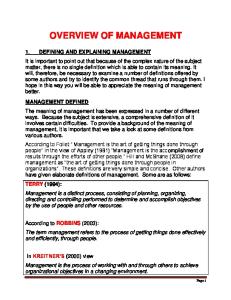
DesignModeler Overview Toolbars
Tree Outline
Sketching and Modeling Tabs
Graphics Window / Viewer
Details View
DesignModeler Overview (cont.) 1. Graphics Window - rotate, zoom, and manipulate geometry
2. Details View - displays details of selected object and allows for editing
3. Tree Outline and Sketching Toolbars - Modeling: displays tree structure of created objects - Sketching: contains options for creating and modifying options a) Draw b) Modify c) Dimensions d) Constraints e) Settings
Tree Outline - Modeling 1. Planes - defined as foundation of geometry.
2. Sketches - contain points, lines, and arcs used as framework of geometry.
3. Operations: extrude, revolve, sweep - create bodies for computational domain. • Tree Outline illustrates each object, its order of creation, and its association to other objects. • Objects may be altered/deleted once created.
Tree Outline - Sketching 1. Draw - build the framework of geometry on active plane. - allows creation of: a.) construction points b.) lines: tangent, by 2 tangents, poly c.) arcs: by tangent, by 3 points, by center d.) shapes: rectangle, circle, polygon
Tree Outline – Sketching (cont.) 2. Modify - alter defined sketches. - allows modification of: a.) fillets b.) chamfers c.) corners d.) modify line: trim, extend, split, drag e.) other: cut, copy, past, move, duplicate...
Tree Outline – Sketching (cont.) 3. Dimensions - define size of dimensions in sketches. - allows definition of: a.) horizontal and vertical b.) radius and diameter c.) angle d.) move: location of defined dimension
Tree Outline – Sketching (cont.) 4. Constraints - define constraints of sketches. - allows constraint of: a.) horizontal and vertical b.) perpendicular and tangent c.) coincident d.) symmetry e.) equal radius, length, distance
Tree Outline – Sketching (cont.) 5. Settings - create grid for placement of points.: a.) turn on grid and allow snap b.) major grid spacing c.) minor-steps per major d.) snaps per minor
Geometry: Pulley
tg
tp
Dh
rh Dp
rg
• Pulley geometry with five bolt holes and a groove.
Parameters Parameter
Symbol
Value
pulley diameter
Dp
60 mm
hole diameter
Dh
5 mm
radius to hole
rh
20 mm
pulley thickness
tp
10 mm
groove thickness
tg
6 mm
groove radius
rg
28 mm
Workbench 1. Create new directory •
called Pulley
2. Open ANSYS Workbench 3. Create Empty Project
4. Save file in new directory: pulley.wbdb •
File - Save
5. Open new geometry in DesignModeler •
On left side of page click on New Geometry
6. Select unit of length •
Select Millimeter, OK
7. Create circle for pulley diameter •
In Tree Outline, select XYPlane.
•
In Toolbar, select Look at Face/Plane/Sketch This normalizes the workplane in the Viewer.
•
In Tree Outline under Sketching tab, select Draw – Circle.
•
Left-click on global origin (Note that a “P” appears at global origin to indicate an auto-constraint) and left-click anywhere else in viewer to create a circle of arbitrary radius.
•
In Tree Outline under Sketching tab, select Dimensions – Diameter.
•
Select circle in viewer. In Details View, change D1 to 60 mm. Enter.
icon.
8. Extrude circle into cylinder •
Right-click in Viewer, select Isometric View.
•
In Toolbar, select Extrude icon.
•
In Details View, change FD1, Depth (>0) to 10 mm.
•
In Toolbar, select Generate icon.
9. Create hexagon for hole placement •
Select Look At icon.
•
In Toolbar, select New Sketch icon. Note that Sketch2 appears in Tree Outline under XYPlane. Further note that Sketch1 was previously created and contains circle.
•
In Tree Outline in Sketching tab, select Draw – Polygon. Set n equal to 5.
•
Select global origin (ensure “P” is visible when selecting).
•
Select an arbitrary point on the positive Y axis. (ensure “C” appears to make sure point is constrained to axis).
•
In Tree Outline in Sketching tab, select Dimensions – Vertical.
•
Select the global origin and the point created on the positive Y axis. (“P” should be visible during both selections)
9. Create hexagon for hole placement (cont.) •
Left-click anywhere in Viewer to place dimension description.
•
In Details View, change V2 to 20 mm. Enter.
10. Save file •
File – Save. pulley.agdb.
11. Create holes for bolt pattern •
Click on XYPlane in Tree Outline to ensure it is still active.
•
Click New Sketch
•
Tree Outline – Sketching – Draw – Circle.
•
Create a circle auto-constrained on the top vertex of the hexagon.
•
Create a circle at each vertex of the hexagon. Important: Watch for “R” to appear before clicking to define radius. In this way, you are constraining each circle to have the same radius.
icon in Toolbar to create Sketch3.
12. Dimension circles for holes •
Tree Outline – Sketching – Dimensions – Diameter
•
Specify diameter of top circle to be 5 mm.
•
Note that all circles should change diameter at this time. Play around with this a little, enjoy yourself.
13. Create bolt holes •
Toolbar – Extrude
•
Details View – Operation: Cut Material
•
Details View – Extent Type: Through All
•
Toolbar – Generate
•
In Projects page, select File – Save All.
14. Create sketch for cutting groove •
Activate ZXPlane in Tree Outline.
•
Toolbar – New Sketch
•
Toolbar – Look At
•
Tree Outline – Sketching – Draw – Rectangle
•
Draw a rectangle in the approximate position as shown below.
15. Dimension Rectangle •
Tree Outline – Sketching – Dimensions – General
•
Left-click on z-axis, then left-click on line with lowest x coordinate. Dimension object should appear. Left-click in Viewer to position it.
•
Left-click and drag line with highest z coordinate. Release left mouse button to position new dimension object.
•
Repeat for line with highest x coordinate.
•
Left-click on x-axis, then left-click on line with lowest zcoordinate. Left-click in Viewer to position dimension object.
15. Dimension Rectangle (cont.) •
In Details View, update each dimension as indicated.
6 mm 2 mm
4 mm
28 mm
16. Create Pulley Groove •
Ensure Sketch4 is active in Tree Outline – Modeling.
•
Toolbar – Revolve. Note that Axis is highlighted in Details View. This indicates that an axis needs to be selected about which the rotation will occur.
•
Select z axis in Viewer. Apply.
•
Details View – Operation: Cut Material
•
Details View – FD1, Angle (>0): 360
•
Toolbar: Generate
•
In Projects page, select File – Save All.
Parametric Modeling • Design modeler has capability of making dimensions into variables. • Dimensions may then be set as functions of other dimensions. • Useful when performing parametric studies of geometries and their changing effect on flow patterns and temperature distributions.
• We would like to set the following parameter functionality:
rh =
Dp 3
rg =
Dp 2
−2
17. Promote pulley diameter to parameter •
Ensure Sketch1 is active in Tree Outline – Modeling.
•
In the Details View, check the box next to D1.
•
A dialog box will appear. Enter Dp in the Parameter Name box. OK.
Note this dimension may be named differently in your project. It should correspond to the pulley diameter.
18. Promote other variables •
Ensure Sketch2 is active in Tree Outline – Modeling.
•
In the Details View, check the box next to V3.
•
A dialog box will appear. Enter rh in the Parameter Name box. OK.
Note this dimension may be named differently in your project. It should correspond to the radius to holes.
18. Promote other variables (cont.) •
Ensure Sketch4 is active in Tree Outline – Modeling.
•
In the Details View, check the box next to L2.
•
A dialog box will appear. Enter rg in the Parameter Name box. OK.
Note this dimension may be named differently in your project. It should correspond to the groove radius.
19. Create functions in Parameter Manager •
In the Toolbar, select Parameters
icon.
•
Parameter Manager will appear at bottom of screen. The Design Parameters tab should contain the created variables.
19. Create functions in Parameter Manager (cont.) •
Under the Parameter/Dimension Assignments tab in the Parameter Manager, three equations appear.
•
Note the @ proceeds a variable created in the Design Parameters tab. All of these dimensions are set values.
•
However, we really want to change the rh and rg to be DRIVEN by changing the expressions that define the dimension.
19. Create functions in Parameter Manager (cont.) •
Under the Parameter/Dimension Assignments tab in the Parameter Manager, set the equations to the following.
•
The radius to hole and groove radius dimensions are now functions of the pulley diameter.
•
In the Design Parameters tab, change Dp to equal 30.
•
Toolbar – Generate
•
The pulley dimensions should update, retaining the equations for the appropriate dimensions.
•
Change the value of Dp to a value of your choosing. The geometry should generate in the same proportions.
•
Check the new values of the driven parameters by clicking on the Check tab.
20. Save and end project •
Return Dp to its original value and generate the model.
•
In Projects page, select File – Save All.
•
Close up shop.