DESIGN PRINCIPALS FOR EARTHQUAKE - RESISTANT BUILDINGS ( Lessons through the failures -- A post earthquake study) By: Shri. A M. Ranade ( Structural Consultant ), Ravi Ranade (Structural / NDT Consultant ) “Kanchan Bhavan” , 5 , Shilavihar Colony, Karve Road, Erandawane, PUNE 411038 INDIA Tel / Fax :- +91 - 20 - 2543 2643 Mobile :- +91 94220 07479 Res.:- +91 - 20 – 25437561
E-mail -
[email protected] OR
[email protected] General :Two major earthquakes have hit India in last seven years. The first in Killari (Latur ) Maharashtra on 30th September 1993 ( Magnitude 6.4, deaths – about 10,000) and the second recently at Bhuj Gujrat on 26th January 2001 ( Magnitude 6.9 or 8.1 ? , deaths – more than 35,000 ? ) . As against this USA had two earthquakes of similar magnitude one in California on 17th January 1994 (Magnitude 6.6, deaths – 57 ) and second in Ciatel near Canada on 1st March 2001 (Magnitude 6.8, deaths – 1) It shows clearly that the damage to structures and loss of life is more in developing countries like India as compared to developed countries like USA, Japan. This is probably due to, lack of awareness in adopting IS Codal provisions for earthquake resistant design, differences in the types and quality of constructions. Design process for earthquake resistant buildings is no doubt a laborious one. Still today earthquake engineering is in development stage , lot of data is required to make sound provisions. But due to availability of advance fast computer and softwares, this task of laborious calculations has become easy. It is to kept in mind that the structure is not designed for the actual earthquake force but it is designed for a much lesser force, as against structures is designed for actual gravity and wind loading conditions. Thus it is accepted that, due to major earthquake a building structure may suffer major damage ( but shall not collapse and there by saving the lives), whereas for wind and gravity loads even minor damage will not be acceptable. And hence it should be our aim to design a structure in such a way that, it will be at least an earthquake resistant . Please note that it is highly expensive to construct structure 100 % earthquake proof. Human Response to Earthquake ( From Key , 1988 ) Stage
Time
Reaction
Event Positive
1 2 3
0 - 1 Minute 1 Minute to 1 week Aftershocks 1 week tp 1 Dimishing month Aftershocks
5
1 month to 1 year 1 year to 10 years
6
10 years to the next time
7
Major The next time Earthquake
4
Negative
Major Earthquake
Panic Rescue & Survival
Fear Allocation of blame to Builders, Designers, official etc
Short term repairs Long term repairs, Action for higher standards
Diminishing interest Reluctance to meet costs of seismic provisions etc., Increasing non-compliance with regulations Repeat stages 1 - 7
Page - 1 / 9
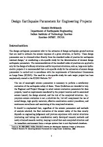
Learning from failures :It shall be kept in mind that, Earthquake engineering is not to be learned from books only, but it is to be learned from the failures demonstrated by the earthquake. The difference between failures due to static loads and cyclic loading can only be learned from the failure patterns observed at earthquake damaged structures. Hence it is very necessary to have the first hand personal inspection of the collapse of the structures during the earthquakes as far as possible. Study of the existing buildings, which are subjected to aftershocks, should also be studied in detail. An important aspect of post-earthquake study is the realising importance of quality construction, proper placement / detailing of reinforcement, proper sizing of members, improving capacity of members especially columns, designing the joints as moment resisting and not as free ones and even proper architectural planning etc. Earthquake Magnitude :Magnitude of a Local earthquake is defined as the logarithm to the base of 10 of the maximum seismic wave amplitude ( in thousands of mm ) recorded at a distance of 100 Kms from the earthquake epicenter. With increase in magnitude by 1.0, the energy released by the earthquake increases by a factor of about 30. Thus , a magnitude 8.0 earthquake releases about 30 times energy released by a magnitude 7.0 earthquake or about 900 times energy released by a 6.0 earthquake. Lateral Analysis & design of RCC structure :In normal residential , commercial types of buildings RCC slabs are usually very stiff in their own plain, that it can be assumed to be infinitely rigid body and will move all vertical members i.e. columns with equal displacement. Such an assumption is termed as “ Rigid Floor Diaphragm”. The distribution of earthquake force will be decided by Rigid Floor Diaphragm action. In reality a floor slab may not be Rigid Floor Diaphragm nor floor diaphragm will have in plane stiffness as zero. Buildings having L, T, U, H or + shapes many a times have connection of two wings by a very small slab link. These weak slab diaphragms connections are overstressed and they do not act as fully rigid diaphragm. It is observed that such slabs are torn off due to high concentration of forces. In Ahmedabad such type of failure was observed in many of the buildings. To transfer lateral load from floor diaphragm to the foundation, suitable vertical elements are required. They may be Moment resisting frames, Shear walls, Bracings or a combination of these. Shear wall is essentially a column with large depth and small width. In general shear wall tend to be laterally much more stiff than moment resisting frames. It is advantageous to use combination of shear wall and moment resisting frame( Fig. 1 ).It is necessary to design the frame for at least 25 % of design force in case of a structure having a combination of shear wall and moment resisting frame. This is essential, because if shear walls fail, there may be sudden collapse of building. If some of the storey is going to have sudden reduction stiffness, such as parking floor without walls, it is referred as soft storey. Soft storey attracts plastic deformation resulting in the collapse of the building. Many such failures due to soft storey were observed in Ahmedabad. For a good seismic performance it is necessary to have high redundancy, thus even after failure of one of member the structure may not fail ( Fig. 2 ). If they are monolithically connected to each other and if yielding takes place in one of them, then a redistribution of forces take place.
Page - 2 / 9
Fig - 1
Fig - 2
Page - 3 / 9
Ductility : Ductility is the capacity of the structure or a member to undergo deformation beyond yield without loosing much of the load carrying capacity. The design philosophy for frames is to avoid failure of columns, from both axial load and bending moment consideration. Lack of stiffness or strength in the column will lead to formation of plastic hinge in them. Under such condition it is preferred to have a formation of moment hinge in the beams instead of column. A column failure may lead to collapse of building but beam failure will be a localised failure. This philosophy of design is called as strong column and weak beam philosophy ( Fig – 3 ). A flexural member exhibits large ductility before collapse, if it undergoes tension failure. This can be achieved by designing section as under-reinforced and providing limits on minimum and maximum reinforcement, thus improving the ductility. To develop full curvature and to behave in ductile manner, the member shall not fail in diagonal shear before formation of plastic hinge. Hence most seismic codes impose restriction on maximum tension reinforcement in flexural member ( beam ) and require closely spaced stirrups at ends of beams.
Fig - 3 Building / Structural Configuration :Buildings with simple and regular configuration with direst load transfer path perform much well during earthquake. In buildings with plan irregularity, the load distribution to different vertical elements becomes complex and require a three dimensional dynamic analysis. Though sophisticated analysis with the use computers can be made for buildings with irregular configurations, this is not the solution for the problems caused by irregular configuration. Hence the seismic configuration is an important consideration at the stage of architectural planning of a building. In seismic design of building , architect and structural engineers need to actively interact with each other to arrive at a structural system, which is necessarily aseismic. If we have a poor configuration to start with , all the engineer can do is to provide a band-aid – improve a Page - 4 / 9
basically poor solution as best as he can. Conversely , if we start with a good configuration and a reasonable framing system, even a poor engineer can’t harm its ultimate performance too much ( By Henry J. Degenkolb, a renowned earthquake engineer ) A slenderness ratio ( height divided by least lateral dimension ) and aspect ratio ( length divided by width , both in plan ) of a building are measures of relative proportions in plan and in elevation. Slenderness ratio must be restricted to small value as possible and it is ideal to keep aspect ratio as close to unity. Footprint of a building is defined as a total plan area of vertical elements like walls, columns and braces as percentage of the gross floor area. This factor is about 50 % in older and monumental structures , like Taj Mahal, and between 1 to 3 % in modern multi-storey buildings A re-entrant corner in plan is an interior corner at which two bays or two portions of a building meet. Buildings having L, T, U, H or + shapes have such re-entrant corners. All buildings that are concave, have re-entrant corners. Re-entrant corner have concentration of stresses, further torsional effect may cause stresses at these notches.
Fig. - 4 Page - 5 / 9
In many of the past earthquakes including Ahmedabad ,the buildings having re-entrant corners are observed to suffer a major damage or collapse of one of the wing. An earthquake force tries to overturn the building , thus overloading the end / corner columns. A corner column in frame system must be designed conservatively from seismic consideration. In Ahmedabad it was observed that many of the buildings, corner columns were severely damaged. Infill wall stiffness :It is common practice to treat infill walls as non-structural elements and to ignore the strength and stiffness contributed by them. They normally participate in the behavior of structure. Unreinforced brick masonry infills in RC moment resisting frame are observed to make the building stiffer by as much as 4 times in comparison to the bare RC moment resisting frames Thus ignoring stiffness of infill walls may lead to calculating higher fundamental period ( T ) and decrease in the design force. Hence the revised IS – 1893 suggests to use the expression for calculating T as ; T = 0.09 H / √d and not as T = 0.1 n as per old code Dynamic Analysis : A dynamic analysis may yield very high fundamental period , which may be unusually high and that the empirical equation usually give a more reliable estimation of fundamental period. The intention is to rely upon the dynamic analysis primarily for distribution of earthquake force with building height, and to different vertical elements of the building and not for assessing the magnitude of design seismic force. Dynamic analysis shows that dynamic eccentricity is higher than the calculated eccentricity ( i.e. difference between point of centre of mass and centre of stiffness ). This phenomenon is accounted in the code by specifying design eccentricity as 1.5 times calculated eccentricity. However many softwares can not take this effect into account due to their limitations, thus requiring special care. Behavior of Buildings in Past Earthquakes :The failures can be categorised as follows – • Failure due to building structure - Building as a whole - Individual members • Failures due to soil conditions Structural collapse may occur at any level and may be due to lateral or torsional displacements, local failure of supporting members, excessive foundation movement and it may also be due to impact of very close adjoining structure which collapse during the earthquake. Some building may not collapse entirely but they do suffer extensive structural damage and thus become unsafe and hence are required to be demolished at any cost. Some structures which receive minor damage can be strengthened or retrofit and can be made reasonably fit for human living. Building having soft storey ( entire parking floor at ground ), L , [ shape , without shear wall will have a major damage / collapse. When two buildings are very close or if they have movement joint then in that case two sides are likely dash against each other. Major structural damage can result due to this, particularly if the floor levels differ. This can very well be avoided by the architect & designer at planning stage only. ( Fig 5 )
Page - 6 / 9
Appendages to buildings - such as masonry parapets, penthouses, roof tanks, claddings, unduly loaded cantilevers (either balconies or beams), very thin size and floating columns generally behave very badly during the severe shocks. The reasons for this is (i) they are designed without any ductility, and (ii) effects of dynamic by the building to which they are attached may greatly increase the forces applied to them. Hence such projections should be avoided as far as possible. Where these are unavoidable these components should be properly anchored with the building with proper analysis and design.
Fig. - 5 Typical damage to elements subjected to bending, with or without direct force are as under :− Cracking in the tension zone. − Diagonal cracking in the core. − Loss of concrete cover. − The concrete core breaking into lumps by reversing diagonal cracking. − Stirrups bursting outwards. − Buckling of main reinforcement. − Bond failure, particularly in zones where there are high cyclic stresses in the concrete. − Direct shear failure of short elements, or those constrained so that only a short length is effectively free. − Shear cracking the beam-column junction. − Tearing of slabs at discontinuities, and junctions with stiff vertical elements. − Diagonal cracking in shear walls, particularly concentrated around openings.
Ground behavior: a) During the violent shaking there is always an increase in the lateral and vertical forces. which disturbs the stability of the non-cohesive soils with the result that the buildings do sink down, tilt or ultimately collapse down. This is a clear case of massive foundation failures. b) Shear movements may also occur either at the surface or at deep levels which also cause damage to the underground structures which also should be investigated in depth. c) During the earthquakes elastic displacements also occur which are very critical in the design of piles, underground pipelines, and culvert-type structures. Failure of these do effect the work of post-earthquake rehabilitation works.
Page - 7 / 9
Here are some do’s and don’ts to be followed for analysis and design of multi storey buildings – Do’s Don’ts Planning stage Simple planning Irregular shapes L, T, [, H Involve Structural Engineer Long cantilevers, overhangs Convex shapes Concave shapes Less slenderness ratio Abrupt change in plan/ Aspect ratio near unity elevation Proper placement of core shaft Plaza type planning Heavy Mass at roof Structural Design stage
Select proper method of analysis
Conduct soil investigation for foundations resting soft soils Moment resisting frame Combination of Moment resisting frames + shear walls Sufficient redundancy ( frames ) Strong column & weak beam Minimum column size 200 mm Proper estimation of fundamental Period Ductile detailing is essential Design shear reinf. for column
For multi storey building design for gravity load is inadequate Rest open foundations on alluvial / B.C. soils Simply supported beams Parking floor without any shear wall / bracing Floating columns Beam depths up to lintel level Avoid 150 mm thk. columns Neglect Effect of infill walls Lift shaft with Masonry
Construction stage
Proper testing of all materials Lapping of column / beam Vibrated concrete for column bars near column–beam junct. Grade of concrete in column - beam junction has to be that of column Sufficient development lengths for Never hide any construction reinforcement defect Keep record of all architectural / structural as built drawings with owner / society.
After Earthquake
Provide Steel props preferably resting on hard strata If cracks are minor – grout them with epoxy non shrink grout After consultation with structural engineer jacket columns right upto foundation / under storey Study the alternative path for transfer of load Carry out proper NDT / structural investigation After proper analysis suggest / carry out retrofitting Page - 8 / 9
Prop only at end of cantilever Plaster the cracked members Localized jacketing of column without removing plaster Decide to retain/demolish any damaged structure without any detail investigation
Conclusions: Every disastrous earthquake yields valuable experience on the performance of man made structures as well as post-earthquake solutions. It is very well acknowledged that earthquake engineering has progressed more from the experienced gained from actual earthquakes than from laboratory tests. We therefore can draw a fair conclusion that unless we study properly the behavior of the various elements of the buildings under actual collapse, we will not feel or have the proper understanding of the effects of the ground motion on the constructed buildings during the earthquakes.This lesson will only help us to correct our knowledge in the design process. If we fail to learn this, then be prepared for the consequences to be faced latter on for our negligence in carrying out our duty as a Structural Engineer!. In the last I can say that the if the structural engineers follow the provisions of the relevant I.S. codes, then many of the failures of buildings can be avoided, if not at least the damages and loss of lives can be minimised. Let’s pray god , not to have earthquakes , but never the less we shall be well prepared to face it.
Page - 9 / 9