16th IEEE International Conference on Control Applications Part of IEEE Multi-conference on Systems and Control Singapore, 1-3 October 2007
TuB03.3
Daisy Chaining Based Visual Servo Control Part II: Extensions, Applications and Open Problems1 G. Hu, N. Gans, S. Mehta, and W. E. Dixon Department of Mechanical and Aerospace Engineering, University of Florida, Gainesville, FL 32611-6250 Email: {gqhu, ngans, siddhart, wdixon}@ufl.edu
Abstract— In this paper, the open problems and applications of a daisy chaining visual servo control strategy are given. This paper is Part II of [22] in which a tracking problem using the daisy chaining strategy is addressed. The main idea of the daisy chaining strategy is to use multi-view geometry to relate coordinate frames attached to the moving camera, moving planar patch, and the desired planar patch specified by an a priori image. Geometric constructs developed for traditional camera-in-hand problems are fused with fixedcamera geometry to develop a set of Euclidean homographies. Based on the homographies, the corresponding rotation and translation components can be extracted for use in the control development. Different from the traditional camera-to-hand and camera-in-hand visual servo control configurations, two cameras are used to construct the homography relationships and estimate the pose of an object modeled as a planar patch (e.g., an unmanned ground vehicle (UGV) or an unmanned air vehicle (UAV)) when in case the object is out of the field of view (FOV), or when the current and desired poses of the object are within the FOV of a single camera.
I. I NTRODUCTION The Euclidean position and orientation (i.e., pose) of a planar patch (e.g., a surface of an unmanned ground vehicle (UGV) or an unmanned air vehicle (UAV)) is typically required for autonomous navigation and control. Conventional UGV or UAV control relies heavily on global positioning systems (GPS) and inertial measurement units (IMUs) to follow trajectories encoded in the task-space (i.e., navigational waypoints). However, GPS may not be available in many environments, and IMUs can drift and accumulate errors over time in a similar manner as dead reckoning. These issues have motivated the interest and advancement in vision-based navigation. Advances in computation and vision (e.g., image extraction/interpretation) technology provide an approach for pose measurement of autonomous vehicles. Over the past decade, visual servo regulation/tracking control has been extensively addressed for both camera-to-hand and camerain-hand configurations [23]. For both camera-to-hand and camera-in-hand configurations, the field of view (FOV) problem is always a challenging issue. For example, the current and desired poses of the object may not be within the FOV of a single camera at 1 This research is supported in part by the NSF CAREER award CMS0547448, AFOSR contract numbers F49620-03-1-0381 and F49620-03-10170, AFRL contract number FA4819-05-D-0011, research grant No. US3715-05 from BARD, the United States - Israel Binational Agricultural Research and Development Fund at the University of Florida, and funding from DARPA (Approved for Public Release, Distribution Unlimited).
1-4244-0443-6/07/$20.00 ©2007 IEEE.
the same time. Additionally, for both of these configurations, either the camera or the object must be stationary if the task is to position the camera relative to some fixed coordinate frame. However, for some systems where both the object and the camera are moving, only the relative velocity can be determined. For example, consider an application an unmanned airborne camera used to provide translation and rotation information of a moving vehicle with the objective of tracking the a priori determined time-varying trajectory of another vehicle recorded from a series of satellite images. This example remains a challenge in visual servoing. Motivated by the FOV issue and the relative velocity issue, an innovative new daisy chaining idea [22], [29], [30] is proposed to link a series of projective homographies so that all the relationships can be expressed in terms of a constant reference frame. Specifically, a multi-view geometry based approach is exploited to construct geometric relationships between various planar patches and camera coordinate systems. By relating the coordinate frames in this way, a measurable error system for a controlled planar patch can be developed. In Part I [22] of this paper, the daisy chaining method is presented, and an asymptotic tracking controller is designed to control the motion of a planar patch. This development represents the simplest case of a fully actuated, six degrees of freedom (DOF) planar patch, a fixed reference camera, assumptions on the configuration of feature points within their planar patches, and a single reference object always in the FOV of both of the current and reference cameras. In this paper, we discuss methods to relax these assumptions and to provide a general solution. We also discuss applications that include control of systems with nonholonomic constraints and extend the method to vision-based estimation methods. Comments are also provided regarding remaining open issues. Some of these topics appear separately in other papers. In [29] and [30], a moving airborne monocular camera is used to provide pose measurements of a planar patch to achieve the visual servo regulation and tracking control of a three DOF UGV, respectively. The results in [29] and [30] are restricted to the three DOF UGV (because of an assumption on the normal to the plane). In Part I of this paper [22], the tracking problem of a six DOF planar patch using a quaternion formulation is presented. Using the daisy chaining strategy, pose estimation of an aircraft and velocity estimation of a spinning satellite are addressed in [25] and [14],
729
TuB03.3
respectively. This paper concisely summarizes these works, and discusses ongoing and future work. In addition to the problems in [14], [22], [25], [29] and [30], the daisy chaining visual servo control strategy may be a promising approach to address some additional open problems in robotics and vision as discussed in this paper. II. E XTENSIONS The daisy chaining method presented in [22] has several assumptions and restrictions that could possibly be weakened or removed. In this section, we detail these assumptions and present extensions to the general daisy chaining algorithm. Most of these extensions are based on the addition of a moving reference camera and some geometric knowledge of the scene. A. Moving Reference Camera
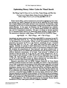
Snapshot pose of camera Current Camera
Reference M Camera
I
IR
I
s2i F*
Reference Object *
π
en Curr h Patc
s1i
t
s1i π
F
Desired Patch Trajectory
Fd
πd
Fig. 1. Problem scenario for six DOF daisy chaining visual servo control using a moving reference camera.
Consider a single camera that is navigating (e.g., by remote controlled aircraft) above a moving planar patch as shown in Fig. 1. The moving coordinate frame I is attached to the airborne camera, the moving coordinate frame IM is attached to a second airborne camera which took the desired image sequences, and the fixed coordinate frame IR is a snapshot of IM . The moving coordinate frame F is attached to the planar patch π which is represented in the camera image by four feature points that are coplanar and not collinear. While viewing the feature points of the planar patch π, the camera is assumed to also view four additional coplanar and non-collinear feature points of a stationary reference object π ∗ . The stationary coordinate frame F ∗ is attached to the reference object. A desired trajectory is defined by a prerecorded, time-varying trajectory of Fd that is assumed to be second-order differentiable. The feature points that define π ∗ are also assumed to be visible when the camera is a priori located coincident with the pose of the stationary coordinate frame IR and the time-varying coordinate frame IM. The challenge of the problem is two-fold. The first challenge is how to solve the relative velocities among the moving current camera I, the moving reference camera IM , the moving current and desired planar patches, and
find the homography relationships. The next challenge is how to estimate the unknown time-varying depth information among the cameras and planar patches. Tracking control of an unmanned ground vehicle in this case has been partially addressed in [30]. In [30], the moving planar patch is assumed to be parallel to the reference object plane, such that the planar patch can only perform three DOF motion. The general six DOF motion with prerecorded video taken by a moving camera is an extension of the approach in [22]. B. Unknown Depth Information In the daisy chaining visual servo control strategy, the estimation of the unknown depth information between the camera the planar patch is an important issue. By using multiview geometry, the unknown time-varying depth information can be related to a constant depth using the homography relationships. Then a certainty equivalence based adaptive law can be used to estimate the unknown constant depth up to a scale. This unknown depth issue is only partially resolved in [4] because there are some situations (see Section IV-A) where the approach in [4] may not be applicable. If the reference camera is moving and some geometric information about the points s1i or s2i is known, then it is possible to recover the unknown depths. As shown in [14], if a single length (e.g. ks1i k) is known, it is possible to estimate the pose of the frames F and F ∗ in the camera frames I, IR and IM . Furthermore, it is possible to estimate all s1i and s2i in their respective frames as well as m ¯ rdi (t), m ¯ ∗ri (t), m ¯ ∗i (t) and m ¯ i (t). The development of these estimates requires that all objects be momentarily static while the camera moves; however, objects are free to move once the vectors s1i and s2i are known. In the case of a controlled UGV, it is reasonable that a length is known and that it can be momentarily stopped in the scene while the camera moves. If the reference camera is static, or a length cannot be known, then another approach must be taken, such as the adaptive control law in [4]. C. Weakening the Assumption Imposed on the Feature Points Configuration In [22], an assumption is imposed on the feature points such that the difference between the Euclidean distances (s2i − s1i ) is a constant ∀i = 1, ..., 4. This assumption means that the unknown constant Euclidean distances s2i and s1i are different by some unknown scalar multiple. While there are many practical applications that satisfy this assumption (e.g., a simple scenario is that the objects attached to F and F ∗ are the same object), the assumption is generally restrictive. Again, if the reference camera is also moving and a single length (e.g. ks1i k) is known, it is possible to estimate the pose of the frames F and F ∗ in the camera frame I. Furthermore, it is possible to estimate all s1i and s2i in their respective frames. This requires that all object be momentarily static while the camera moves, however objects are free to move once the vectors s1i and s2i are known. This gives R(t), R∗ (t), Rrd (t), Rr∗ (t), n∗ (t), and the depth ratios αi (t). All other geometric relations can be computed from these signals. The use of geometric relations eliminates the
730
TuB03.3
need for the homography equations between different objects as in equations (19)-(23) in [22]. III. A PPLICATIONS A. Control of Moving Target via a Moving Camera In [15], a visual servo controller is developed to asymptotically regulate the pose of a planar patch to a constant pose defined by a goal image, where the camera is mounted on-board a planar patch (i.e., the camera-in-hand problem). Since many practical applications require a robotic system to move along a predefined or dynamically changing trajectory, the regulation result in [15] was extended in [7] to address the planar patch tracking problem. Note that due to nonholonomic constraints, the planar patch tracking problem does not reduce to the planar patch regulation problem. In [6], a stationary overhead camera (i.e., the camera-to-hand or fixed camera configuration) was used to track a planar patch to a desired pose. The daisy chaining method allows us to extend this problem to the case of a moving airborne camera. This is possible by continuously relating the pose of the object and camera to some static reference object. 1) Visual Servo Regulation/Tracking Control of a Three DOF UGV: In [29], multi-view geometry is used to relate coordinate frames attached to the moving camera, moving UGV, and the desired UGV pose specified by an a priori image. Geometric constructs developed for traditional camerain-hand problems are fused with fixed-camera geometry to develop a set of Euclidean homographies. One of the resulting Euclidean homographies is not measurable through a set of spatiotemporal images (i.e., a corresponding projective homography can not be developed as in previous results). Hence, new geometric relationships are formulated to solve for the homography so that a measurable error system for the nonholonomic UGV can be developed. The resulting open-loop error system is expressed in a form that is amenable to a variety of UGV controllers. A benchmark controller originally proposed in [33] is proven to yield the regulation result through a Lyapunov-based stability analysis. An outcome of this paper is a new geometric framework to relate the pose of a moving object to a stationary object via a moving camera. In [30], a moving airborne camera is used to provide sensor feedback so that the UGV follows the same trajectory (e.g., a video recorded by a human piloted aircraft) as the desired UGV. Applications that can build on this framework include: collaborative UGV/unmanned air vehicle (UAV) visual servo control, tracking moving targets with a moving on-board camera (camera-in-hand), and formation keeping/platooning. 2) Visual Servo Tracking Control of a Six DOF Planar Patch: In [22], a collaborative quaternion-based visual servo kinematic controller is developed to enable an object represented by a planar patch of feature points to track a desired trajectory determined by a sequence of prerecorded images. An application of the development in [22] is for an unmanned aircraft to provide translation and rotation information to another moving vehicle with the objective of tracking the a
priori determined time-varying trajectory of another vehicle recorded from a series of satellite images. There are several issues in the six DOF case that differ from the three DOF case. First, the normal of the six DOF planar patch, and the depth information between the moving camera and the moving six DOF planar patch or the reference patch are unknown (the normal is constant in the three DOF case). By using the depth ratios obtained from the homography decomposition, the unknown depth information is related to an unknown constant depth value. Then an adaptive law is designed to estimate this unknown constant depth up to some scale. By decomposing the homography relationships, the normal to the moving (translational and rotational) planar patch can be obtained, which is required for the controller development. B. Visibility and Field of View Visual servo controllers often require the image-space coordinates of the Euclidean feature points in the control development; hence the feature points must remain in the camera’s FOV. Since the FOV of conventional perspective cameras (e.g., pinhole cameras) is restricted, keeping the feature points in the FOV is a fundamental challenge for visual servo control algorithms, especially when the geometrical model of the object or the camera parameters are unknown. The fundamental nature of the FOV problem has resulted in a variety of control and path planning methods (e.g., [3], [5], [8], [10], [11], [18], [26], [31], [38]). Research in [8], [10] and [17] used partitioned or switching visual servoing methods to keep the object in the FOV. In [5], [11], [31] and [38], potential fields (or navigation functions) are used to ensure the visibility of all features during the control task. In [3], the focal length of the camera was automatically adjusted (i.e., zoom control) to keep all features in the FOV during the control task by using an intrinsic-free visual servoing approach developed in [26]. In [18], a continuous controller is obtained by using a new smooth task function with weighted features that allows visibility changes in the image features (i.e., some features can come in and out of the FOV) during the control task. Some researchers have also investigated methods to enlarge the FOV (e.g., [19], [24], [35], [36], [34]). In [19], [24], [35] and [36], image mosaicing is used to capture multiple images at each scene point as a camera moves and stitch these images together to obtain a larger image. In [34], multiple images are fused from multiple cameras mounted in order to have minimally overlapping FOV. In the daisy chaining visual servo control strategy, the visibility restriction in the conventional camera-to-hand configuration is weakened because the current pose and desired poses of the planar patch don’t have to be within the FOV at the same time. As shown in [22], the current pose of the planar patch is only required to be within the FOV of the current camera, and the desired pose of the planar patch is only required to be within the FOV of the reference camera. By utilizing multi-view geometry, homographic relationships
731
TuB03.3
can be obtained to relate the current camera, the reference camera, and the current and desired poses of the planar patch. C. Vision Based State Estimation 1) Pose Estimation of an Aerial Vehicle: While GPS is the most widely used sensor modality for pose estimation in aircraft navigation, researchers have been motivated to investigate other navigation sensors due to the need to operate in GPS denied environments. As an alternative/collaborative sensor to GPS systems, cameras can act as navigational sensors by detecting and tracking feature points in an image. In [25], a new daisy chaining vision-based state estimation method was proposed that allows sets of feature points to be related such that the aircraft poses can be correlated to previous GPS data so that GPS-like navigation can be maintained in denied environments. Feature points will continuously enter and leave the FOV of a moving aircraft. Through use of the daisy chaining method, the estimator in [25] accepts new sets of feature points as they enter the FOV and links them to previous sets of points through geometric reconstruction. As the relationship between each set of points is consecutively chained together, the current pose is updated with respect to the previous information. In this way, the current pose can be estimated even as previous sets of points leave the FOV. 2) Pose Estimation of a Moving Rigid Body: It is often necessary to track an object that may partially leave the FOV or be partially occluded. This includes the case of an object rotating such that points visible at one time may later be occluded by the object itself when they face away from the camera. If the object is a rigid body composed of planar surfaces, the daisy chaining method can be used to relate the geometric relationship of each planar surface relative to each other planar surface. In this way, points can be occluded or leave the FOV, as long as points on another surface remain visible, the position of the lost feature points can be estimated. This problem is addressed in [14] with the motivation of tracking a rotating satellite with a single camera. D. SFM and SLAM With the advantages in resolving the FOV issue, the daisy chaining strategy can be applied to address the structure from motion (SFM) problem and the simultaneous localization and mapping (SLAM) problem. While the previous applications represent problems that have been at least partially addressed, the SFM and SLAM applications represent future work and avenues for exploration. SFM: As stated in [9], an adaptive nonlinear estimator is developed to identify the Euclidean coordinates of feature points on a moving object using a single fixed camera. By using the daisy chaining strategy, the development in [9] can partially be extended to address one degenerate case that can not be handled by the traditional SFM techniques. As shown in Fig. 2, the coordinate frames I and IR are attached to a current camera and a fixed reference camera,
respectively. The coordinate frames F and F ∗ are attached to the object and the reference patch, respectively. When the object (attached to F) is visible to the current camera (attached to I), the traditional SFM framework can be used. However, when the object is outside the camera’s FOV (attached to I), the traditional SFM framework cannot be applied. By using the daisy chaining strategy, the 2D projection of the object (attached to F) may still be obtained by utilizing the fixed reference camera. Hence, the structure can still be obtained. Reference R Camera
I
Current Camera
I
Reference Object
π*
s2i F*
ent Curr h π Patc
s1i F
Fig. 2. Problem scenario for strcuture from motion using daisy chaining strategy.
SLAM: Usually in SLAM [12], the 2D image information gathered from a moving camera is utilized to estimate both the motion of the camera as well as position of static features in the environment. By using the daisy chaining strategy, the static features out of the FOV can also be obtained. Hence the application domain of SLAM will be expanded. In [25], the pose estimation problem has been addressed based on the daisy chaining strategy. In order to use this strategy to address the SLAM problem using small vehicles (e.g., a mobile robot, or an unmanned air vehicle), there are several open challenges. The first challenge is reseeding2 reference patches to achieve long-term persistent autonomy. This ability is only partially addressed in [25]. Another issue is that feature points extracted from an unknown scene must be separated into coplanar subsets [1], [32]. IV. O PEN P ROBLEMS In order to construct a general daisy chaining visual servo control strategy, there are several open challenging issues to be addressed. Open problems include: the unknown depth information issue, the robustness issue (or the camera calibration error issue), the reference patch reseeding issue, and the error propagation issue. A. Unknown Depth Information As mentioned in Section II-B, if the reference camera is moving and a single length between two feature points is known, the depths of all the feature points can be determined. 2 A new patch composed of a set of feature points is used as the reference patch when the current reference patch leaves the FOV.
732
TuB03.3
If this is not the case, an adaptive control law, like that in [4] could be used to compensate for this lack of information. However, there are two cases where an adaptive control law may not be applicable.
Reference R Camera
I
Current Camera
I
(Rrd , xfrd)
(R*,x*f )
d*
Reference Object
(R,x f)
Reference R Camera
I
(R*r,x*fr)
Reference Object
π*n+1
d
* πn+2
s(n+1)i
s(n+2)i
*1 Fn+
* Fn+2
sni π*n Fn*
s2i Current Camera
Reference Object
Reference Object *
I
π
s1i π
F
Desired Patch Trajectory
s1i π
F
s1i Desired Patch Trajectory
Fd
πd
Fig. 4. Problem Scenario for daisy chaining visual servo control strategy in which a moving current camera and reseeding multiple reference planar patches are used.
s1i
ent Curr h Patc
ent Curr h Patc
Fd πd
Fig. 3. Problem scenario for daisy chaining visual servo control strategy in which the current camera is attached to the moving reference planar patch.
1) Reference Planar Patch affixed to the Current Camera: As shown in Fig. 3, the current camera attached to coordinate frame I is affixed to the reference planar patch. An example of this case is that the current camera is mounted on an unmanned aircraft on which there are feature points visible to the reference camera. The movement of the reference planar patch presents a challenge, because the distance from either the current camera or the fixed reference camera to the moving planar patch is time-varying. For the three DOF motion (i.e., the planar patches π and π d move in the same plane), the distance from the fixed reference camera to the planar patch πd is a constant although it is unknown. By utilizing homographies, all the unknown time-varying depth can be related to this constant depth, and an adaptive law can be designed to estimate this constant depth up to a scale term. However, estimating the unknown depth information for the six DOF problem remains an open challenge. 2) Moving Reference Planar Patch: The system of a moving reference planar patch can be described by Fig. 1 in [22]. The moving reference planar patch makes the problem more difficult to solve because the depth information between either the current camera or the fixed reference camera and the moving planar patches is time-varying and unknown. This presents a challenge to design an adaptive law to estimate the unknown time-varying depth. B. Moving Current Camera and Reseeding Multiple Reference Planar Patches If there is only one stationary reference patch which is required to be within the FOV of the cameras (both the current camera and the reference camera), then the task space of the object will be restricted. To eliminate this restriction, multiple reference patches can be used in the control strategy such that the moving range of the object will be enlarged. As
∗ ∗ shown in Fig. 4, the coordinate frames Fn∗ , Fn+1 and Fn+2 are attached to three sequential reference planar patches π ∗n , π ∗n+1 and π∗n+2 , respectively. As the current camera attached to the time-varying coordinate frame I is moving, different planar patches will be sequentially used as the reference patch. As mentioned in Section III-C, the reseeding problem has been solved in terms of pose estimation but not used in a control law. Since all the reference patches are stationary, the depth between each camera and each planar patch can be obtained by combining the homography relationships and an adaptive update law. The challenge of this problem is how to design a continuous controller or switch controllers smoothly when transferring between planar patches while guaranteeing closed-loop stability.
C. Robustness with respect to Uncalibrated Camera Parameters Like any vision-based algorithm, if the camera calibration parameters are not exactly known, then performance degradation and unpredictable response from the system may occur. The robustness issue has not been addressed for the daisy chaining problem. There are at least two possible approaches to solve this issue. One method is to design a model-free controller based on the best-guess estimation of the calibration matrix. The other approach is to write the error system depending on the calibration matrix in a linearly parameterized form, and an adaptive law could be used to estimate the unknown constant parameters. D. Error Propagation Issue The homography relationships between the moving cameras, the reference patch and the object are obtained based on the 2D images. Another open problem associated with the daisy chaining method is the propagation of errors. In practice, the feature point tracker, homography decomposition, and state estimation will result in a discrepancy between the estimated and actual unknown inertial coordinates of an object. As images are chained together this discrepancy can be propagated leading to degraded response.
733
TuB03.3
The error propagation issue is not unique to the daisy chaining method and is common in navigation methods such as dead reckoning. Communication networks also suffer from the propagation of errors and may offer some insight into methods to resolve the error propagation issue. For example, in [2], the error propagation issue in a sensor network was addressed, in which the signal is transformed in a sensor network whose measurement precision is restricted by the noisy “relative measurements”. In [37], the error propagation on the Euclidean motion group (e.g., error propagation in manipulator kinematics) was addressed by using the group theory. V. C ONCLUSIONS This paper is an extension of [22] in which a tracking problem using the daisy chaining strategy is addressed. In this paper, the open problems, extensions and applications of this approach are provided. R EFERENCES [1] C. Baillard and A. Zisserman, “Automatic Reconstruction of Piecewise Planar Models from Multiple Views,” IEEE Int. Conf. on Computer Vision and Pattern Recognition, 1999, pp. 559-565. [2] P. Barooah and J. P. Hespanha, “Optimal Estimation from Relative Measurements: Error Scaling (Extended Abstract),” IEEE Int. Conf. on Distributed Computing in Sensor Systems, June 2006. [3] S. Benhimane and E. Malis, “Vision-based Control with Respect to Planar and Nonplanar Objects Using a Zooming Camera,” IEEE Int. Conf. on Advanced Robotics, 2003, pp. 991-996. [4] J. Chen, D. M. Dawson, W. E. Dixon, and A. Behal, “Adaptive Homography-Based Visual Servo Tracking for Fixed and Camera-inHand Configurations,” IEEE Trans. on Control Systems Technology, Vol. 13, No. 5, pp. 814-825, (2005). [5] J. Chen, D. M. Dawson, W. E. Dixon, and V. Chitrakaran, “Navigation Function Based Visual Servo Control,” Automatica, accepted, to appear. [6] J. Chen, W. E. Dixon, D. M. Dawson, and V. Chitrakaran, “Visual Servo Tracking Control of a Wheeled Mobile Robot with a Monocular Fixed Camera,” IEEE Conf. on Control Applications, 2004, pp. 10611066. [7] J. Chen, W. E. Dixon, D. M. Dawson, and M. McIntire, “Homographybased Visual Servo Tracking Control of a Wheeled Mobile Robot,” IEEE Int. Conf. on Intelligent Robots and Systems, 2003, pp. 18141819. [8] G. Chesi, K. Hashimoto, D. Prattichizzo, and A. Vicino, “Keeping Features in the Field of View in Eye-In-Hand Visual Servoing: A Switching Approach,” IEEE Trans. on Robotics, Vol. 20, No. 5, pp. 908-913, (2004). [9] V. K. Chitrakaran, D. M. Dawson, J. Chen, and W. E. Dixon, “Euclidean Position Estimation of Features on a Moving Object Using a Single Camera: A Lyapunov-Based Approach,” IEEE American Control Conf., 2005, pp. 4601-4606. [10] P. I. Corke and S. Hutchinson, “A New Partitioned Approach to Image Based Control,” IEEE Trans. on Robotics and Automation, Vol. 17, No. 4, pp. 507-515, (2001). [11] N. J. Cowan, J. D. Weingarten, and D. E. Koditscheck, “Visual Servoing via Navigation Function,” IEEE Trans. on Robotics and Automation, Vol. 18, No. 4, pp. 521-533, (2002). [12] G. Dissanayake, P. Newman, S. Clark, H. F. Durrant-Whyte, and M. Csorba, “A Solution to the Simultaneous Localisation and Map Building (SLAM) Problem,” IEEE Trans. on Robotics and Automation, Vol. 17, No. 3, pp. 229-241, (2001). [13] W. E. Dixon, A. Behal, D. M. Dawson, and S. Nagarkatti, Nonlinear Control of Engineering Systems: A Lyapunov-Based Approach, Birkhäuser Boston, 2003. [14] K. Dupree, N. Gans, and W. E. Dixon, “Euclidean Calculation of Feature Points of a Rotating Satellite: A Daisy Chaining Approach,” IEEE American Control Conf., 2007, accepted, to appear.
[15] Y. Fang, A. Behal, W. E. Dixon and D. M. Dawson, “Adaptive 2.5D Visual Servoing of Kinematically Redundant Robot Manipulators,” IEEE Conf. on Decision and Control, 2002, pp. 2860-2865. [16] Y. Fang, D. M. Dawson, W. E. Dixon, and P. Chawda, “HomographyBased Visual Servoing of Wheeled Mobile Robots,” IEEE Trans. on Systems, Man, and Cybernetics -Part B: Cybernetics, Vol. 35, No. 5, pp. 1041-1050, (2005). [17] N. Gans and S. Hutchinson, “A Switching Approach to Visual Servo Control,” IEEE Int. Symp. on Intelligent Control, 2002, pp. 770-776. [18] N. Garck¸a-Aracil, E. Malis, R. Aracil-Santonja, and C. Pérez-Vidal, “Continuous Visual Servoing Despite the Changes of Visibility in Image Features,” IEEE Trans. on Robotics, Vol. 21, No. 6, pp. 12141220, (2005). [19] S. Hsu, H. S. Sawhney, and R. Kumar, “Automated Mosaics via Topology Inference,” IEEE Computer Graphics and Application, Vol. 22, No. 2, pp. 44-54, (2002). [20] G. Hu, W. E. Dixon, S. Gupta, and N. Fitz-coy, “A Quaternion Formulation for Homography-based Visual Servo Control,” IEEE Int. Conf. on Robotics and Automation, 2006, pp. 2391-2396. [21] G. Hu, S. Gupta, and N. Fitz-coy, W. E. Dixon, “Lyapunov-Based Visual Servo Tracking Control Via A Quaternion Formulation,” IEEE Conf. on Decision and Control, 2006, pp. 3861-3866. [22] G. Hu, S. Mehta, N. Gans, and W. E. Dixon, “Daisy Chaining Based Visual Servo Control Part I: Adaptive Quaternion-Based Tracking Control,” IEEE Multi-Conf. on Systems and Control, 2007. [23] S. Hutchinson, G. D. Hager, and P. I. Corke, “A Tutorial on Visual Servo Control,” IEEE Trans. on Robotics and Automation, Vol. 12, No. 5, pp. 651-670, (1996). [24] M. Irani, P. Anandan, J. Bergen, R. Kumar, and S. Hsu, “Efficient Representations of Video Sequences and Their Application,” Signal Processing: Image communication, Vol. 8, pp. 327-351, (1996). [25] K. Kaiser, N. Gans, S. Mehta, and W. E. Dixon, “Position and Orientation of an Aerial Vehicle through Chained, Vision-Based Pose Reconstruction,” AIAA Guidance, Navigation, and Control Conf., 2006. [26] E. Malis, “Visual Servoing Invariant to Changes in Camera Intrinsic Parameters,” IEEE Int. Conf. on Computer Vision, 2001, pp. 704-709. [27] E. Malis and F. Chaumette, “2 1/2 D Visual Servoing with Respect to Unknown Objects Through a New Estimation Scheme of Camera Displacement,” Int. J. of Computer Vision, Vol. 37, No. 1, pp. 79-97, (2000). [28] E. Malis, F. Chaumette, and S. Bodet, “2 1/2 D Visual Servoing,” IEEE Trans. on Robotics and Automation, Vol. 15, No. 2, pp. 238250, (1999). [29] S. Mehta, W. E. Dixon, D. MacArthur, C. D. Crane, “Visual Servo Control of an Unmanned Ground Vehicle via a Moving Airborne Monocular Camera,” IEEE American Control Conf., 2006, pp. 52765211. [30] S. Mehta, G. Hu, N. Gans, and W. E. Dixon, “Adaptive Vision-Based Collaborative Tracking Control of An UGV via a Moving Airborne Camera: A Daisy Chaining Approach,” IEEE Conf. on Decision and Control, 2006, pp. 3867-3872. [31] Y. Mezouar and F. Chaumette, “Path Planning for Robust Image-Based Control,” IEEE Trans. on Robotics and Automation, Vol. 18, No. 4, pp. 534-549, (2002). [32] K. Okada, S. Kagami, M. Inaba, and H. Inoue, “Plane Segment Finder: Algorithm, Implementation and Applications,” IEEE Int. Conf. on Robotics and Automation, 2001, pp. 2120-2125. [33] C. Samson, “Control of Chained Systems Application to Path Following and Time-Varying Point-Stabilization of Mobile Robots”, IEEE Trans. on Automatic Control, Vol. 40, No. 1, pp. 64-77, (1995). [34] R. Swaminathan and S. Nayar, “Non-metric Calibration of Wide-angle Lenses and Polycameras,” IEEE Conf. on Computer Vision and Pattern Recognition, 2000, pp. 413-419. [35] Y. Y. Schechner and S. Nayar, “Generalized Mosaicing: High Dynamic Range in a Wide Field of View,” Int. J. of Computer Vision, Vol. 53, No. 3, pp. 245-267, (2003). [36] A. Smolic and T. Wiegand, “High-Resolution Image Mosaicing,” IEEE Int. Conf. on Image Processing, 2001, pp. 872-875. [37] Y. Wang and G. S. Chirikjian, “Error Propagation on the Euclidean Group With Applications to Manipulator Kinematics,” IEEE Trans. on Robotics, Vol. 22, No. 4, pp. 591-602, (2006). [38] H. Zhang and J. Ostrowski, “Visual Motion Planning for Mobile Robots,” IEEE Trans. on Robotics and Automation, Vol. 18, No. 2, pp. 199-208, (2002).
734