CT-MAC: A MAC Protocol for Underwater MIMO Based Network Uplink Communications Yu Luo, Lina Pu, Zheng Peng, Zhong Zhou, Jun-Hong Cui Computer Science & Engineering Department University of Connecticut, Storrs, CT 06029
{yu.luo, lina.pu, zhengpeng, zhongzhou, jcui}@engr.uconn.edu ABSTRACT Due to high bandwidth-efficiency, Multiple-Input MultipleOutput (MIMO) has emerged as a promising technique to address the low bandwidth challenges in underwater acoustic networks. Although extensive research has been conducted at the physical layer for underwater MIMO communications, the corresponding medium access control (MAC) is still largely unexplored, which makes it difficult to apply the existing underwater MIMO technologies in real applications. In this paper, we propose a distributed MAC protocol, called Coordinated Transmission MAC (CT-MAC), for underwater MIMO based network uplink communications. In CT-MAC, an efficient coordination scheme among immediate neighbors is designed for channel competition, which can avoid flooding overhead in the network. This scheme could also effectively address the long propagation delay problem and the collisions among long control packets in underwater acoustic communications. Protocol performance in terms of throughput and energy efficiency is evaluated via simulations which show significant improvements over handshaking based and random access based MIMO MAC approaches.
1.
INTRODUCTION
In underwater environments, acoustic waves are usually used for communication as electromagnetic waves could not propagate far due to fast attenuation in water. The special characteristics of underwater acoustic channels with limited available bandwidth, however, pose grand challenges for high speed wireless underwater communications [1, 2, 3, 4]. In wireless RF communications, extensive research has been conducted to improve the bandwidth efficiency, among which, multiple-input multiple-output (MIMO) that enables collision-free parallel transmissions over the same frequency, is very promising because of the dramatically increased channel capacity [5, 6]. In the past several years, there have been significant research efforts on underwater physical layer point to point MIMO technology [7, 8, 9]. In [7], a sparse partial response equalizer (sPRE) is developed for shallow
Permission to make digital or hard copies of all or part of this work for personal or classroom use is granted without fee provided that copies are not made or distributed for profit or commercial advantage and that copies bear this notice and the full citation on the first page. To copy otherwise, to republish, to post on servers or to redistribute to lists, requires prior specific permission and/or a fee. WUWNet’12, Nov. 5 - 6, 2012 Los Angeles, California, USA. Copyright 2012 ACM 978-1-4503-1773-3/12/11 ... $15.00.
water MIMO acoustic communications, where the long channel impulse responses have been considered. The taps of sPRE can be chosen to be sparse, and therefore allows better exploitation of the multipath diversity inherent in intersymbol interference channels. In [8], the authors present a MIMO-OFDM system design approach, which takes into account the Doppler compensation, underwater channel estimation, interference cancellation as well as subcarrier detection. In a network with shared media, medium access control (MAC) provides a coordination mechanism among multiple users to avoid interference. An efficient MAC protocol is required to fully utilize the parallel transmission capability in MIMO techniques. Most of existing underwater MAC protocols [10, 11, 12, 13, 14], however, are designed for singleinput single-output (SISO) systems, and are often not efficient in MIMO systems. Moreover, the MAC protocols for terrestrial MIMO networks cannot work directly underwater because of the unique characteristics of underwater acoustic communications, which include: • Long propagation delays. The speed of sound in water is about 1.5 × 10³ m/s, five orders of magnitude lower than the radio propagation speed, 3 × 10⁸ m/s. This introduces long propagation delays in underwater acoustic communications. Despite of the multipacket reception capacity in MIMO systems, collision still occurs when the number of overlapped packets exceeds the Degree of Freedom at the receiver side. In the conventional MIMO-based wireless communication system, this supersaturation problem can be addressed by carrier sensing or handshaking mechanisms [15]. In underwater environments, however, long propagation delays make these mechanisms inefficient [11, 16]. Thus, new mechanisms are needed to solve the challenges caused by long propagation delays. • Fast varying channels in both frequency domain and time domain. In most of the traditional MIMObased MAC protocols, the transmitter channel state information is obtained by open-loop or closed-loop methods for power allocation optimization as well as interference suppression [15, 17]. However, such feedback mechanisms cannot be applied to the underwater environment because the acoustic multipath channel varies fast with several factors such as wave height, wind speed and surface roughness and hence are hard to predict. The feedback delay of underwater communication is usually larger than the channel correlation
time and makes open or closed loop feedback mechanisms ineffective in the practical underwater MIMO applications. • Long preamble and half duplex mode of acoustic modems. The long preamble of real acoustic modem is another problem that makes the handshaking based MAC protocol inefficient in the underwater communication system [18, 19, 20]. Due to the complex underwater acoustic channel, a long fixed preamble sequence is often used in underwater acoustic modems for signal synchronization, automatic gain control (AGC) and channel estimation purposes [21, 22, 23]. In Table 1, we list the preamble length, transmission rate, as well as the overall duration time of the small control packet (6 bytes) for three different acoustic modems. From Table 1, it is obvious that the control packet is no longer short any more when considering the long preamble of acoustic modems. In the MIMO uplink communication system, interference among these long control packets significantly can degrade the performance of handshaking based MIMO MAC protocols, especially in high traffic scenarios. Unique features of underwater MIMO networks call for a new MAC design that has the ability to avoid interference among data transmissions to improve the energy efficiency, and at the same time address the problems caused by the long propagation delays and collisions among control packets to increase the throughput of the networks. In this paper, we propose a new coordinated transmission MAC protocol, called CT-MAC, for underwater MIMO uplink communications. Underwater MIMO uplink communications, in which signals from underwater sensors or vehicles are transmitted to a surface buoy or a control center, enable a wide range of important aquatic applications, such as pollution monitoring, underwater target detection as well as scientific exploration [19, 20]. In CT-MAC, we introduce an effective coordination competition scheme. Instead of broadcasting control packets to the entire network, which is very energy consuming, nodes only exchange competition information with immediate neighbors and obtain the global information via relays. With this coordination scheme, the collision free data transmission is achieved with low energy consumption and short delays. We compare the performance of CT-MAC with several existing MIMO uplink MAC approaches (designed for terrestrial wireless networks) in terms of throughput and energy efficiency via simulation. The results show that CT-MAC offers significant performance improvement, even without optimal power allocation strategy at the transmitter side. The rest of the paper is organized as follows. We present the network architecture in Section 2. The design of CTMAC is elaborated in Section 3 and some theoretical analysis is conducted in Section 4. We compare the performance of CT-MAC with several typical MIMO MAC protocols in Section 5. Finally draw our conclusions and give some future work in Section 6.
2.
NETWORK ARCHITECTURE
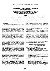
In this paper, we consider an uplink communication system where a group of nodes all communicate with a common receiver, such as a buoy in an underwater data collection system or a base station (BS) in environment monitoring
applications. A typical network architecture of the uplink communication system is shown in Fig. 1. There are L underwater nodes, each equipped with Mt transducers, and a BS with Mr hydrophones. We assume that block coding is employed at the physical layer in order to achieve good reliability performance in a MIMO communication system [25].
Base station
Node2 Node3
Node4 Node5
Node1
L users
Figure 1: An uplink communication system. The sum-rate capacity of MIMO communication system with a constant channel can be found in [26], but we primarily focus on the frequency selective fading channel which is often used for the underwater environment. According to [27], if each channel is zero mean spatially white and each node has the same transmission power, the sum-rate channel capacity of the uplink with perfect channel state information in a high signal-to-noise ratio (SNR) situation can be approximated as: Cuplink ≈ min (Mr , KMt ) log (SN Ravg ),
(1)
where SN Ravg is the average SNR at the BS and K is the number of active nodes. Note that in order to maximize the channel capacity without collisions, the MIMO MAC protocol should guarantee the number of active nodes approaching to Mr /Mt in (1). Both starving (KMt < Mr ) and supersaturated situations (KMt >Mr ) will degrade the performance of the network. In addition, block decoding requires that the packets from different nodes arriving at the BS simultaneously to avoid block interference. In Section 3, we will introduce our protocol and show how the CT-MAC achieves these two goals.
3.
CT-MAC PROTOCOL DESIGN
We suppose the time synchronization among all nodes is available in the network [28, 29, 30]. The key idea of CT-MAC is to utilize local information exchange to achieve global coordinations. The time and energy consumption are significantly reduced because control packets only exchange among intermediate neighbors within a short distance. With this coordinated transmission scheme, CTMAC reduces propagation delay of the acoustic channel and is immune to the problem caused by long preamble sequence as well as fast fading characteristics of the underwater system. As a result, considerable performance improvement on channel utilization and energy efficiency can be achieved with CT-MAC. In this section, we present the basic idea of CT-MAC in an one-dimensional (1D) example first and then extend it to
Table 1: Total Control Packet (6 Bytes) Duration with Different Acoustic Modem Modem Type
Data Rate
Preamble Duration Time (sec)
Total Control Packet Duration Time (sec) ≈ 1.56s
800bps (Standard) ≈ 1.5
Benthos ATM-88X Modem
≈ 1.52
2.4Kbps (Highest) Aqua-fModem [24]
3.045Kbps
0.49
0.66
80bps (Standard) WHOI Micro Modem
1.47 0.87
300-5000bps (High PSK mode)
a more general two-dimensional (2D) network.
3.1
CT-MAC in One-Dimension Networks
CT-MAC contains two stages: initialization and continuous transmission stage. In the initialization stage, network nodes exchange control packets in order to get the initial global network information. After the initialization stage, all nodes in the network obtain the information regarding the network status. And then data packet can be transmitted without collisions in the second stage. In CT-MAC, time is divided into equal time slots and each slot is called a transmission cycle (TC). Each TC consists of a competition and a data transmission phase as shown in Fig. 3. In the following, we describe the two stages in details. Initialization Stage: During the competition phase of a transmission cycle, every node with packets to send first sends out a competition packet (CP), which contains the priority level (PL) information to compete for later data transmission. Since each node can only receive the competition packets from its immediate neighbors, in the initialization phase, every node cannot obtain the global network information and is not allowed to transmit data packets. In the succeeding competition phase of the initialization stage, every node forwards the new priority level information received in the previous TC. This process continues until all nodes in the network obtain global competition information generated in the first round. During the initialization stage, since the network nodes have not received global competition information, all nodes will hold their data packets. Fig. 2 shows an example of the PL relay mechanism among three nodes. In the first transmission cycle, edge nodes 1 and 3 are blind to the priority information of each other due to the local competition packets exchange. The information on the global network status is obtained until the second transmission cycle, with the aid of Node2 for the PL forwarding. In Fig. 2, the red PLs are self generated in the current cycle, and the PLs received from neighbors are marked as blue. The black PLs are history PLs received in previous cycles. Continuous Transmission Stage: This stage starts from the cycle when all network nodes have acquired the network’s status for the first time. In the competition phase of continuous transmission stages, every node still transmits the competition packet which includes all the new priority information (the priority level of sender node and the priority level that it received from others in the last transmission cycle). Starting from T C2 in Fig. 2, coordinated transmission is achieved in each T Cn when n ≥ 2 with the message P Li,n−1 . Because of this continuous CP relay mechanism, all nodes obtain a new round of global information in each transmission cycle in this stage. During the data transmission phase, only K out of L nodes
1.52
Node2
Node1 TC1: PL11
Node3 PL21
PL31
TC2:
PL11 PL12
PL21 PL22
PL31
PL11 PL12
PL21 PL22
PL31 PL32
PL11
PL21 PL22
PL31 PL32
TC3:
PL12 PL13
PL22 PL23
PL32
PL12 PL13
PL22 PL . 23
PL32 PL33
PL12
PL22 PL . 23
PL32 PL33
PL1,n-1 PL1,n
PL2,n-1 PL3,n-1 PL2,n PL3,n
PL1,n-1
PL2,n-1 PL3,n-1 PL2,n PL3,n
PL21
PL11
. . .
PL21
PL31
. .
. .
PL1,n-1 PL2,n-1 PL3,n-1 TCn: PL1,n PL2,n
Start from TC2, a consensus on the PL information is obtained shown in the first row of each PL matrix. Each node uses this matrix to justify whether it wins the sending opportunity or not.
Figure 2: The PL matrix update mechanism. with highest priority levels win the data transmission opportunities, where K is the parallel transmission capacity of MIMO link and L is the amount of users in the network. It is obvious that after delayed L−2 transmission cycles, the data sending requirements at T Ci are processed in a coordinative way. Because of this reason, the protocol is named as coordinated transmission MAC (CT-MAC). In Fig. 3, we demonstrate the work flow of one-dimension CT-MAC at the continuous transmission stage (the data transmission is temporarily held back at the initialization stage). In order to avoid the CP sending-receiving collision, the control packet transmission time of neighbor nodes are staggered as shown in Fig. 3, i.e. the group of nodes with even ID will send the CP first and then listen CPs from their neighbor nodes. The process is reversed on the nodes with an odd ID. Transmission Phase T1
CP21
CP11
Data
t
CP11CP31
CP21
T2
Data
t
CP21 CP41
T3
CP31
Data
t
CP31 CP 51
T4
. . .
CP41
. Competition Phase . . Beginning Time
Data Data Transmission Phase
t
Figure 3: The sequence diagram of the onedimensional CT-MAC. The solid line refers to the transmitted packet, the dash line is the received packets. The starting time of the transmission cycle on each node is adjusted by an offset called time advance in order to compensate for the propagation delay and make sure data packets from different nodes arrived at the BS simultaneously. The time advance can be estimated during node ID alloca-
tion discussed in Section 3.3. The CP transmissions are collision free by employing multi-packet reception [31] technique. The process of node ID assignment will be discussed in the 2-D topology situation.
3.2
Extension to 2-D Networks
In many existing aquatic applications such as underwater data collection and environment monitoring, the sensors are deployed around a single buoy or base station forming a two dimensional network. The coverage of the surface monitor can be modeled as a circle area limited by its communication range. In this section, we show how to extend the onedimension CT-MAC to a 2-D network. …. ….
one way propagation delay τi according to the sending and arriving time stamps and reply with a simple tone immediately. According to the arriving time of tones, the BS is able to estimate its distance to the furthest and nearest users denoted as Df ur and Dnear and divides the network into rings. 2 The radius of circular area is Cr = (Df2 ur − Ddep )1/2 , where Ddep is the average node depth. Then the propagation delay from the base station to the nodes in the ith ring is approximately r r � � (3−2i) (1−2i) 2 2 (Cr + davg )2 +Ddep (Cr + 2 davg )2 +Ddep 2 , , c c Cr 1 1 ≤ i ≤ b davg + 2 c τi∈ �r � (3−2i) 2 (Cr + davg )2 +Ddep D2 2 r , dep , i = b dC + 12 c+1. c c avg
…. 300m 300m ….
….
….
….
….
….
B
C
A …. …. ….
3rd R
ing
R 2nd
where b c is floor operator. davg is the distance between two rings. After this initialization, the BS will broadcast rings segmentation to the whole network and each node decides which ring it resides in according to the propagation delay τi . 4d2D presents the distance difference from the BS to the furthest and to the nearest nodes in the network. Now, timing advance can be calculated based on τi .
ing
ing 1st R
Figure 4: Two-dimension topology. Considering the maximum transmission range of the acoustic modem to be 3 km, the total number of nodes in a two dimensional dense network is roughly 202 ×π/4 ≈ 314, when the average distance between neighbors is 300 m. Here, we divide the circular area into W concentric rings with a width of 300 m - the average distance between neighbor nodes. Therefore, the distances between the BS and the nodes within the same ring are approximately equal. Denote the outermost ring by R1 , and the innermost one by RW as show in Fig. 4. To avoid the sending-receiving collision in 2-D CT-MAC, The nodes in the same ring follow the same timing diagram pattern and the sending of competition packets are staggered between rings. The allocation of the timing of nodes in the ith ring is exactly the same as the ith node in a one dimension scenario (Fig. 3). The increased immediate neighbors in a 2-D topology pose higher requirement on the multi-packet reception to avoid competition packets collision during competition slots. The competition information flows from one ring to another and eventually goes through nodes in the inner ring. Under the relay of internal nodes, the priority information can be finally flooded to the whole network during the initialization phase. Similar to the 1-D scenario, collision free data transmission begins continuously in the following time periods.
3.3
Node and Ring ID Allocation Issues
Finding which ring the node belongs to is one key step of the two-dimensional CT-MAC protocol. Similar approach can be directly employed to the one-dimension situation in determining the node ID. At the initialization stage, the BS first broadcasts a test packet to the whole network to assist the ID finding procedure. Each node can then calculate the
D fu
r
Ddep …. R3
davg
R2 R1
Cr
Figure 5: The boundary measurement of concentric rings.
3.4
Delay of Global Coordination
We define the buffered cycles as the cycles waiting for global PL information, and L as the amount of hops in 1-D topology and the number of ring in 2-D network. Since it takes L − 2 cycles for the global competition information to reach the entire network, the transmission of data packets is also delayed for at least L−2 cycles which could be a problem when applying to some time-critical applications. However in the long term, benefiting from the enhanced throughput performance of CT-MAC, the overall average delay of CT-MAC is acceptable. Moreover, the delayed transmission cycles in CT-MAC is limited by the number of nodes constrained by acoustic communication range, deployment cost and available channel bandwidth, which is small in the underwater uplink communication networks [21, 23, 32].
3.5
False Sending Request Problem
It’s worth noting that, the false sending request phenomenon exists in our protocol. For instance, the packet generated in T C1 will be accumulated when node ` waits for global PL information and this packet will force a sending request in each cycle between T C2 and T CL−1 , even if no more packets are generated. So if node ` wins the competition in T CL−1 and sends out the packet generated in T C1 , the node continues on the competition in time slots between T CL and T C2L−2 even though it has run out of packets. This false sending request arising from the delayed transmission, may waste
sending opportunities and finally decrease the throughput performance. However, the performance degradation is negligible as shown in our simulation. Fig. 6 presents the impact of false sending request on the normalized throughput of the CT-MAC with varying traffic rate. The results demonstrate that the negative impact of buffered transmission on throughput only slightly increases with the number of nodes, L, in the network. Thus, the throughput degradation can be ignored in the application.
0.8
0.6
0.2
0
0.05
0.1 Traffic Rate −− λ
0.15
Forward Flow
Channel Utilization of CT-MAC
As illustrated in Fig. 3, the transmission of competition packets are staggered to avoid control packets collisions. The length of competition slot in one dimension network is tcc = 2 tCP + 4 ∆d1D · c−1 , where tCP is the packet length of competition packet; c ≈ 1500 m/s is the underwater sound speed; ∆d1D = max(|di − dj |), with di and dj as the distance from the BS to a pair of neighbor nodes i and j in the network respectively. Denote the length of data packet as tdata , then the channel utilization of one-dimensional CTMAC becomes Ktdata Ktdata = . tcc + tdata 2tCT + 4∆d1D · c−1 + tdata
TL-2
TL-1
TL
Figure 7: Probability of successful decoding in single hop communication.
0.2
THEORETICAL ANALYSIS
U=
T3
Backward Flow
In this section, we first analyze the channel utilization of CT-MAC and then study the effect of priority level information losses.
4.1
T2
T1
Figure 6: Impact of false sending request on throughput of CT-MAC.
4.
Effect of Priority Level Information Losses
Despite of the collision-free feature of the CT-MAC, this protocol suffers from the potential loss of the priority level packet during the channel competition. In this section, we focus on the impact of PL losses on the system performance with theoretical analysis and simulation results. To characterize the link quality during the PL propagation, we denote p0i as the probability of successful transmission from the ith node to the (i + 1)th node during the forward PL passing, and pi−1 as the probability of successful transmission from the ith node to the (i − 1)th node during the backward PL passing, as shown in Fig. 7.
L=10: without delay L=10: with delay L=15: without delay L=15: with delay L=20: without delay L=20: with delay
0.4
0
4.2
. . .
Normalized Throughput
1
achieving the optimal channel utilization. In the next section, we analyze the impact of PL losses on the performance the CT-MAC.
(2)
For the channel utilization of 2-D square grid topology, the parameter 4d1D in (2) should be replaced with 4d2D . The length of competition slot in handshaking based method is almost ten times higher than CT-MAC, with station-node distance 3km vs. neighbor nodes distance 300 m. This indicates that the PL transfer mechanism in CT-MAC brings on significant channel utilization improvement. Along with the reduced transmission range, the energy consumption for transmission competition is considerably reduced in CTMAC, which further enhances the energy efficiency performance. These performance improvement will be illustrated in Section 5 in detail. No matter in one or two dimensional networks, the PL forwarding mechanism is always the core in CT-MAC for
The probability of successful transmission of PL from the ith node to the j th node thus follows, Qj pk , i > j (backward f low) k=i−1 i=j Pij = 1, (3) Qj−1 0 i < j (f orward f low). k=i pk , In particular, with an identical successfully transmission probability over all links, i.e. pk = pk 0 , p, we have (3) simplified as Pij = p|i−j| ,
i, j = 1, 2 . . . , L .
(4)
Given the formulation in (3), it can be shown that the probability of losing ω PLs for node l is ω
Ql (ω)=
1X (−1)i−1 ψl (i)Q(ω−i), ω = 1, . . . , L. ω i=1
(5)
where �2 L � X 1 ψl (i) = −1 , Pki k=1
and Ql (0) =
L Q
Pil .
(6)
i=1
The average number of lost PLs thus can be put as PLEl =
L X
ω Ql (ω),
(7)
ω=0
which corresponds to the number of missing elements in the PL matrix in Fig. 2. There are several ways to handle this PL loss issue. The first one is to associate the lost PLs information with the highest priority. However, the resulting “winners” in this method will decrease the channel utilization performance, due to the decreased sending opportunity for other users.
Substituting (8) into (2) yields the final channel utilization of the one dimensional CT-MAC � � L P L P K −ω i=1 ω=1 L−ω U= Qi (ω) . (9) tCT 4 ∆d1D 1+2( )+ ( ) tdata c tdata The two-dimension CT-MAC channel utilization can be obtained by replacing ∆d1D by ∆d2D in (9).
Normalized throughput
Another solution is that each node associates the lost PLs with the lowest priority, so that the number of active number of nodes is kept no less than K. However, the MIMO system in this method will have the possibility to work in a supersaturated situation and collision may happen. Hence, we focus on the former scheme and give the closed form of average throughput and channel utilization of CT-MAC for a homogeneous network. Taking the PLs loss into account, the upper bound of multi-packet capacity for CT-MAC is reformulated as � � L P L P K −ω (8) Qi (ω). S= i=1 ω=1 L−ω
Average number of error/lost PLs
Theoretical result: PL lost: p=0.99 PL lost: p=0.995 PL lost: p=0.999
Simulation result: PL lost: p=0.99 PL lost: p=0.995 PL lost: p=0.999
1.5 L=20 1 L=10 0.5
0
5
10 Node ID
15
20
Figure 8: The average number of lost PLs in PL matrix of each node. With a capable physical-layer decoding algorithm, it has been shown that the bit-error-rate (BER) in point-to-point UWAN can be lower than 10−2 [33, 34], meaning that a high successful transmission probability in (3) and (4) can be expected. For the one dimensional network, Fig. 8 and Fig. 9 demonstrate the simulated and theoretical average number of PLs loses and the throughput performance degradation, respectively. We tested two network sizes, i.e. L = 10 and 20. It can be observed in the figure that the simulated results agree well with the theoretical results. Moreover, as the size of the network increases, it is obvious that there is an increase in the average number of lost PLs and a considerable degradation of network throughput. The result can be extend to 2 - D topology with W = 10 and 20 rings directly.
5.
PERFORMANCE COMPARISONS
In this section, we conduct simulations to compare the performance of CT-MAC with several typical MIMO MAC protocols: the random access based channel-aware ALOHA [15], the multi-antenna reception based handshaking method [35], and a simple MIMO-based slotted ALOHA. We will first introduce the simulation settings. We will also briefly describe
Theoretical result:
Simulation result:
1.1
L=10 L=15 L=20
L=10 L=15 L=20
1.05 1 0.95 0.9 0.85 0.8 0.75 0.7 0.99
0.992
0.994
0.996
0.998
1
p
Figure 9: The impact of PL successful decoding probability on the throughput of CT-MAC.
channel-aware ALOHA [15] and multi-antenna reception based MAC [35]. After that, we present some representative simulation results.
5.1 2
1.15
Simulation Settings
To facilitate the performance comparison, a one-dimension network is adopted in the simulations. We set the Ddep , davg and Df ur as 500 m, 200 m and 2 km, respectively. We assume that the surface BS/buoy can receive up to K= 4 packets simultaneously without interference. The network size of one-hop uplink communication system is L=20. Considering the typical characteristics of practical acoustic modems, the preamble length is 0.5 s, the data packet size is 400 bytes, and the transmission data rate is 3 kbps, with the same parameters as Aqua-fModem modems [24]. The PL loss rate is 1% (p = 0.99). The transmission strategy T Sa is employed and the CT size is 40 bytes. The size of the feedback and the RCBC/REQ packets in the channel-aware ALOHA and multi-antenna reception based MAC is 5 bytes. We assume the underwater channel follows the stationary Rayleigh distribution where the average fading level is proportional to the distance between the node and BS. Performance Metrics: We use two performance metrics: channel utilization and average energy overhead. The former metric is a direct measure of throughput; the second metric is defined as the average energy consumption to successfully receive one data packet with the channel fading, packet collision and the control packet overhead. It reflects the performance on energy efficiency. Channel-aware Aloha: In channel aware Aloha [15], the receiver transmits a feedback message after each data reception to provide channel state information for the sender. This open loop feedback only allows nodes with good channel quality to transmit and therefor makes the protocol more efficient. This scheme postpones the user transmissions with poor instantaneous underwater channel quality and thus reduces the collision probability of ALOHA to some extent. multi-antenna reception MAC: In multi-antenna reception MAC [35], a two-way handshaking for a multi-antenna reception protocol is introduced to enable the collision avoidance and dynamic power control. Mini-slot packets are employed in [35] for checking the permission of transmission at the receiver node by utilizing receive capability broadcast (RCBC) packet and request (REQ) packet to help multiple
nodes with best channels capture the sending opportunity and avoid collisions caused by hidden terminal problems.
5.2
Simulation Results
Fig. 10 and Fig. 11 show the channel utilization and average energy overhead of different MIMO-MAC protocols. As illustrated in Fig. 10, CT-MAC outperforms the channelaware ALOHA and the multi-antenna reception MAC in terms of channel utilization, as the latter two protocols suffer from the long propagation delay of the feedback and handshaking messages. Meanwhile, the collisions among control packets also degrades the throughput of the multi-antenna reception MAC. The Slotted Aloha also has good throughput performance even taking into account the high data collision probability, since there is no extra delay for any feedback or control packets. However, the collision among data packets fails Slotted Aloha in term of energy efficiency, which can be found in Fig. 11. 2
energy consumption on collided long control packets makes the multi-antenna reception MAC inefficient. When taking both the energy efficiency and the throughput into account, the CT-MAC shows best performance for underwater MIMO uplink communications.
6.
CONCLUSIONS AND FUTURE WORK
This paper focuses on the MAC protocol design for underwater MIMO networks in an uplink communication scenario. Leveraging a special relay mechanism, competition packets only need to be exchanged among the immediate neighbors. Via this mechanism, CT-MAC significantly improves the network performance in terms of channel utilization and energy efficiency. Both theoretical analysis and simulation results show that CT-MAC has apparent advantages over existing MIMO MAC approaches. Future Work Given the wide application of the underwater uplink communication system, we plan to implement and test CT-MAC on top of the Aqua-fModem [24], which is incorporating MIMO techniques.
1.8
Channel utilization
1.6
7.
CT−MAC Slotted Aloha Channel Aware Aloha Multi−Antenna Reception
1.4 1.2 1 0.8 0.6 0.4 0.2 0
0
0.05
0.1
0.15 Traffic rate −− λ
0.2
0.25
0.3
Figure 10: The channel utilization comparison. 2
10
Average energy overhead
Slotted Aloha Channel Aware Aloha Multi−Antenna Reception CT−MAC
1
10
Channel Aware Aloha (MIMO)
0
0.05
0.1
0.15 Traffic rate −− λ
0.2
0.25
0.3
Figure 11: The energy overhead comparison. In addition, benefiting from the estimation for the channel state information (CSI) through feedback mechanism, the channel-ware ALOHA has the lowest power consumption, as it always allows the users with the best channels to transmit. The proposed CT-MAC has a comparable energy efficiency performance to the channel-ware ALOHA while maintains the highest channel utilization. In contrast, the
REFERENCES
[1] Jun-Hong Cui, Jiejun Kong, Mario Gerla, and Shengli Zhou. Challenges: Building Scalable Mobile Underwater Wireless Sensor Networks for Aquatic Applications. IEEE Network, 20(3):12–18, 2006. [2] Lanbo Liu, Shengli Zhou, and Jun-Hong Cui. Prospects and Problems of Wireless Communication for Underwater Sensor Networks. Wiley Wireless Communications and Mobile Computing, 8(8):977–994, Oct 2008. [3] Jim Partan, Jim Kurose, and Brian Neil Levine. A survey of practical issues in underwater networks. ACM SIGMOBILE Mobile Computing and Communications Review, 11:23–33, Oct. 2007. [4] Jun Liu, Zhaohui Wang, Michael Zuba, Zheng Peng, Jun-Hong Cui, and Shengli Zhou. JSL: Joint Time Synchronization and Localization Design with Stratification Compensation in Mobile Underwater Sensor Networks. In 9th Annual IEEE Communications Society Conference on Sensor, Mesh and Ad Hoc Communications and Networks (SECON), Seoul, Korea, 2012. [5] Amos Lapidoth and Stefan M. Moser. Capacity bounds via duality with applications to multiple-antenna systems on flat-fading channels. IEEE Transactions on Information Theory, 49:2426–2467, 2003. [6] Andrea Goldsmith, Syed Ali Jafar, Nihar Jindal, and Sriram Vishwanath. Capacity Limits of MIMO Channels. IEEE Journal on Selected Areas in Communications, 21(5):684–702, 2003. [7] S. Roy, T.M. Duman, and V.K. McDonald. Error rate improvement in underwater mimo communications using sparse partial response equalization. Oceanic Engineering, IEEE Journal of, 34(2):181 –201, april 2009. [8] Baosheng Li, Jie Huang, Shengli Zhou, K. Ball, M. Stojanovic, L. Freitag, and P. Willett. Mimo-ofdm for high-rate underwater acoustic communications. Oceanic Engineering, IEEE Journal of, 34(4):634 –644, oct. 2009.
[9] Baosheng Li, Jie Huang, Shengli Zhou, K. Ball, M. Stojanovic, L. Freitag, and P. Willett. Further results on high-rate mimo-ofdm underwater acoustic communications. In OCEANS 2008, pages 1 –6, sept. 2008. [10] Nitthita Chirdchoo, WeeSeng Soh, and Kee Chaing Chua. Aloha-based MAC Protocols with Collision Avoidance for Underwater Acoustic Networks. In Proceedings of INFOCOM’07, Mini-Symposium), pages 2271–2275, Apr. 2007. [11] Y. Noh, P. Wang, Uichin Lee, D. Torres, and M. Gerla. DOTS: A propagation Delay-aware Opportunistic MAC protocol for underwater sensor networks. In Proceedings of the 18th IEEE International Conference on Network Protocols (ICNP), pages 183–192, Oct. 2010. [12] M.J. Xiaoxing Guo; Frater, M.R.; Ryan. Design of a Propagation-Delay-Tolerant MAC Protocol for Underwater Acoustic Sensor Networks. IEEE Journal of Oceanic Engineering, pages 170–180, 4 2009. [13] Yibo Zhu, Zhong Zhou, Zheng Peng, Michael Zuba, and Jun-Hong Cui. ICST Transactions on Mobile Communications and Applications, 11(7–9):1–14, Sep 2011. [14] Marcal Molins and Milica Stojanovic. Slotted FAMA: a MAC protocol for underwater acoustic networks. In Proceedings of IEEE OCEANS’06 - Asia Pacific, pages 1–7, May 2006. [15] Xiangping Qin and Randall Berry. Exploiting multiuser diversity for medium access control in wireless networks. In Proceedings of the INFOCOM’03, volume 2, pages 1084–1094, Mar. 2003. [16] B. Peleato and M. Stojanovic. Distance aware collision avoidance protocol for ad-hoc underwater acoustic sensor networks. IEEE Communications Letters, 11(12):1025–1027, Dec. 2007. [17] Karthikeyan Sundaresan, Raghupathy Sivakumar, Mary Ann Ingram, and TaeYoung Chang. Medium access control in ad hoc networks with MIMO links: optimization considerations and algorithms. IEEE Transactions on Mobile Computing, 3(4):350–365, Dec. 2004. [18] Lina Pu, Yu Luo, Yibo Zhu, Zheng Peng, Shruti Khare, Jun-Hong Cui, Benyuan Liu, and Lei Wang. Impact of Real Modem Characteristics on Practical Underwater MAC Design. In Proceedings of IEEE OCEANS’12, May 2012. [19] I. Vasilescu, K. Kotay, D. Rus, M. Dunbabin, and P. Corke. Data Collection, Storage, and Retrieval with an Underwater Sensor Network. In Proceedings of the 3rd international conference on Embedded networked sensor systems, SenSys ’05, pages 154–165, New York, NY, USA, 2005. ACM. [20] Sarfraz Nawaz, Muzammil Hussain, Simon Watson, Niki Trigoni, and Peter N. Green. An Underwater Robotic Network for Monitoring Nuclear Waste Storage Pools. In Proceedings of the 1st International ICST Conference on Sensor Systems and Software (SCUBE), 2009. [21] Teledyne-Benthos Acostic Modems. http://www.benthos.com. [22] LinkQuest. SoundLink High Speed Acoustic Modems.
http://www.link-quest.com/. [23] Zheng Peng, Haining Mo, Jun Liu, Zhaohui Wang, Xiaoka Xu, Son Le, Yibo Zhu, Jun-Hong Cui, Zhijie Shi, and Shengli Zhou. NAMS: A Networked Acoustic Modem System for Underwater Applications. In Proceedings of IEEE OCEANS’11, KONA, Hawaii, Sept 2011. [24] Hai Yan, Shengli Zhou, Zhijie Shi, Jun-Hong Cui, Lei Wan, Jie Huang, and Hao Zhou. DSP Implementation of SISO and MIMO OFDM Acoustic Modems. In OCEANS, pages 1–6. IEEE, May 2010. [25] E. Biglieri, R. Calderbank, and A. Constantinides. MIMO Wireless Communications. Cambridge, U.K.:Cambridge Univ. Press, 2007. [26] Wei Yu, W. Rhee, S. Boyd, and J.M. Ciofli. Iterative water-filling for Gaussian vector multiple access channels. In IEEE International Symposium on Information Theory, page 322, 2001. [27] Hyundong Shin and Jae Hong Lee. Capacity of multiple-antenna fading channels: spatial fading correlation, double scattering, and keyhole. IEEE Transactions on Information Theory, 49(10):2636–2647, Oct. 2003. [28] Jun Liu, Zhong Zhou, Zheng Peng, Jun-Hong Cui, Michael Zuba, and Lance Fiondella. Mobi-sync: Efficient time synchronization for mobile underwater sensor networks. IEEE Transaction on Parallel and Distributed Systems, Feb 2012. [29] Affan A. Syed and John Heidemann. Time synchronization for high latency acoustic networks. In Proceedings of INFOCOM’06. [30] Jun Liu, Zhaohui Wang, Zheng Peng, Michael Zuba, Jun-Hong Cui, and Shengli Zhou. TSMU: A Time Synchronization Scheme for Mobile Underwater Sensor Networks. In Proc. GLOBECOM, Houston, TX, 2011. [31] Guner D. Celik, Gil Zussman., Wajahat F. Khan, and Eytan Modiano. MAC for Networks with Multipacket Reception Capability and Spatially Distributed Nodes. IEEE Transactions on Mobile Computing, 9(2):226–240, Feb. 2010. [32] L. Freitag, M. Grund, S. Singh, J. Partan, P. Koski, and K. Ball. The WHOI micro-modem: an acoustic communications and navigation system for multiple platforms. 2:1086–1092, Sep. 2005. [33] Christian R. Berger, Shengli Zhou, James C. Preisig, and Peter Willett. Sparse Channel Estimation for Multicarrier Underwater Acoustic Communication: From Subspace Methods to Compressed Sensing. 58:1708–1721, Mar. 2010. [34] Jie Huang, Shengli Zhou, and Peter Willett. Nonbinary LDPC Coding for Multicarrier Underwater Acoustic Communication. IEEE Journal on Selected Areas in Communications, 26(9):1684–1696, Dec. 2008. [35] Norihiko Sato. and Takeo Fujii. A MAC Protocol for Multi-Packet Ad-Hoc Wireless Network Utilizing Multi-Antenna. In 6th IEEE Consumer Communications and Networking Conference, CCNC, pages 1–5, Jan. 2009.