USO0RE3 675 2E
United States Patent [19]
[11] E
Koopman, Jr. et al.
[45] Reissued Date of Patent:
[54]
Patent Number:
CRYPTOGRAPHIC AUTHENTICATION OF TRANSMITTED MESSAGES USING PSEUDORANDOM NUMBERS
Re. 36,752 Jun. 27, 2000
OTHER PUBLICATIONS
National Semiconductor Corporation Inc.’s Response to United Technologies Automotive, Inc.’s First Set of Inter
[75] Inventors: Philip J. Koopman, Jr., Pittsburgh, Pa.; Alan M. Finn, Amston, Conn.
rogatories (dated Sep. 2, 1997). Petrovic, Branislav, “A Balanced RF Oscillator”, rf design aWards, no date.
[73] Assignee: United Technologies Automotive, Inc., (List continued on neXt page.)
Dearborn, Mich.
Primary Examiner—Bernarr E. Gregory Attorney, Agent, or Firm—Niro, Scavone, Haller & Niro
[21] Appl. No.: 08/771,526 [22]
Filed:
Dec. 23, 1996
[57]
Related US. Patent Documents
An automobile door receiver module (30) and a plurality of
Reissue of:
[64]
Patent No.:
5,377,270
Issued:
Dec. 27, 1994
Appl. No.:
08/085,423
Filed:
Jun. 30, 1993
keychain fob transmitter units (16) contain identi?cation numbers, secret initial values, and secret feedback masks so as to authenticate encrypted messages from any of the
assigned fobs, indicative of commands registered by closing
[51]
Int. Cl.7 ...................................................... .. H04L 9/00
[52]
US. Cl. ............... .. 380/25; 340/825.31; 340/825.34;
[58]
Field of Search .................................. .. 380/4, 21, 23,
380/21; 380/23; 380/46; 380/48; 380/49
380/24, 25, 30, 43, 46, 48, 49, 50; 340/825.31, 825.34
[56]
References Cited U.S. PATENT DOCUMENTS
Re. 33,189 3,622,991
3/1990 Lee et al. . 11/1971 Lehrer et al. .
3,654,604
4/1972 Crafton.
3,665,162
5/1972 Yamamoto et al. .
4,133,974
1/1979 Morgan.
4,319,273
3/1982 Nossem.
(List continued on neXt page.) FOREIGN PATENT DOCUMENTS 0304733 3 225 754 2144564
5/1993 1/1984 7/1984
European Pat. Off. . Germany . United Kingdom .
ABSTRACT
switches on the fob. Each fob is synchronized With the receiving module by means of a truly random number concatenated With a secret initial value and encrypted, through a linear feedback shift register or other operations. Asecond secret initial value is encrypted and command bits are exclusive ORed into the loW order bit positions; the tWo encrypted numbers are concatenated and encrypted to form a key Word Which is transmitted With the fob ID. Synchro nization includes decrypting to recover the truly random number and the secret initial value concatenated therewith;
the truly random number is compared With previously received random numbers in order to avoid copying of
recently transmitted synchronization commands. Successive lock-related commands utilize the number encrypted from the truly random number and the second secret initial value as starting values, employing a pseudorandom number of
encryption iterations. A half-second delay betWeen responses mitigates gaining access through numerical trials. An authenticated panic alarm command operates the head lights and horn of the vehicle but does not alter the syn chronization.
64 Claims, 9 Drawing Sheets
2827
R6. 36,752 Page 2 US. PATENT DOCUMENTS 4,322,577 4,418,275 4,424,414
3/1982 Brandstrom 11/1983 Oosterbaan et al. . 1/1984 Hellman et al. ........................ .. 380/30
5,243,650
9/1993 Roth et al. .
5,243,653
9/1993 Malek 6161..
5,272,755 572767738 5280267
12/1993 M1y6j16161. . 1/1994 Hirsch _ 1/1994 Reggiani _
4,435,826
3/1984 Matsui-
5,313,491
5/1994 861116111111 6161..
4,509,093
4/1985 Stellberger.
573137530
5/1994 1Wamura_
4,595,985 4,596,985
6/1986 sakakiya 6/1986 Bongard 919l- -
5,317,639 5,319,364
5/1994 M11161111161 . 6/1994 WaIakSa 6161. .
4,612,413
9/1986 RobertetaL-
5,319,710
4,613,980
9/1986 Newlin 9191- -
5,365,225
6/1994 A16116 6161.. 11/1994 13661111111161.
4,630,201 12/1986 White.
5,369,706 11/1994 Latka.
4,654,480
5,377,270 12/1994 KOOpIIlaIl, Jr. 6161. .
3/1987 W955 -
4,667,301
5/1987 Chm 919l- -
5,398,284
3/1995 KOOpIIlaIl, Jr. 6161. .
4,691,291
9/1987 Wolfram
5,412,379
5/1995 WaIakSa 6161..
4,733,215 4,734,680
3/1988 Memmola 3/1988 Gehman et al. .
5,420,925 574347806
5/1995 MichaelS . 7/1995 Hofverberg _
4,736,419
4/1988 R99
5,436,901
7/1995 KOOpIIlaIl .
4,758,835
7/1988 Rathmann et al. .
5,442,341
8/1995 Lambropoulos _
4,771,463
9/1988 Beeman -
5,479,511
4,797,921
1/1989 Shiraishi.
575117124
12/1995 N66666116 .
4/1996 Bergner_
4,800,590
1/1989 Vaughan-
5,517,189
5/1996 1366111111161 6161. .
4,825,210
4/1989 Bachhuber et al. .
575287230
6/1996 Kim _
4,847,614
7/1989 Keller-
5,554,977
9/1996 161116116111 61 61. .
4,853,884
8/1989 Brown et al. .
575557303
9/1996 Stambler _
4,853,962
8/1989 Brockman.
5,563,600 10/1996 M1y6k6.
4,870,682
9/1989 Money 9191- -
5,588,058
4,876,718
10/1989
Citta et al.
4,881,148 4,892,098
11/1989 Lambropoulos et al. . 1/1990 Sauer -
4,905,176
2/1990 SClllllZ.
4,912,463
3/1990 Li .
4,928,098
5/1990
............
. . . . ..
380/21 X
12/1996 L6 B6116 .
575987476
1/1997
576047488 5,619,475
2/1997 Lambropoulos _ 4/1997 W1111<161.
LaBane et a1_ _
OTHER PUBLICATIONS
Dannhaeuser.
_
_
4,942,393 7/1990 Waraksa et a1_ _ 4,980,108 12/1990 Suzuki et a1. .
Morgan, Harvey L., “An Ernitter Follower Oscillator”, rf design feature, no date.
Dernrna, Nick, “Balanced Meissner Oscillator”, rf design
5,001,754
3/1991 De?eyes-
5,007,016
4/1991 Le Mehaute et al. .
awards, Dec” 1993_
570487086
9/1991 Blanco et a1‘ '
Taylor, Craig and Kenny, David, “Basic Crystal Oscillator
5,054,067
10/1991
Moroney et al. .
5,055,701
10/1991
Takeuchi.
.
.
.
.
,,
.
Design Considerations , RF tutorial, no date. “
570607265 10/1991 Finkelsteim 5,103,221 4/1992 M6111111616.
.
,,
.
BroWn, Fred, Stable LC Oscillators , rf design feature, Man, 1987
5,105,162
4/1992 Fleissner et al. .
Mitsurni ICs, “The Best Way to Protect a Microprocessor”,
5,109,152
4/1992 Takagi et al. ....................... .. 380/23 X
[10 date,
5,113,441
5/1992 Harada~
g/ ’
’
/
goblet '
IEEE Industrial Electronics Society, Edited by NeWrnan,
t 1
awamura e a‘ '
5,144,667
9/1992 Pogue, Jr. et al. .................. .. 380/25 X
5,146,215
9/1992 D1611 ............................ .. 340/825.31 X
John G. and Martinsons, Robert, “Autornotive Applications of Microprocessors,” Oct. 25—26, 1984, Dearborn, MI. d
“
.
.
f
db
Bree >Gary A» ABaSlC Revlewo Fee
k,, f
. 1
ac > r “Mona,
5,161,190 11/1992 CaIIIlS .
APT» 1993
5,179,592 5,191,610
1/1993 Kusano . 3/1993 Hill et a1- -
Key, EdWin L., “An Analysis of the Structure and Complex ity of Nonlinear Binary Sequence Generators,” IEEE Trans
5,195,136
3/1993 Hardy 9t a1~ -
actions on Information Theory, Nov., 1976.
5’22O’6O6
6/1993 Greenberg'
Application for Equipment Authorization, Federal Corn
5,220,616
6/1993
Downing et al..
5,222,141
6/1993
K1111611.
572247161 5,231,667 5,241,598
6/1993 Daniel et a1‘ _ 7/1993 K6j11116 . 8/1993 Raith .
. .
-
-
rnrnunications
-
-
Cornrnission,
_
Grantee. .
General
Motors, .
.
Dated Nov. 15, 1990 and grant of Equipment Authorization, Dated? 1219- 14> 1991 Relevant Art to the Cryptography Portfolio, no date.
U.S. Patent
Jun. 27, 2000
000:0
84
Sheet 1 0f 9
Re. 36,752
q-49
.mmcmgsmc Lzscc Jl 39-12mm 7
j
2
|
l6-ID '6
FOB ls) HW-z. 26
25
as MICROPROCESSOR so
9%
asisR FB-XOR
1’? 2g
_l9
s4 s4 8|~
'RNDMCTRF I45‘)
k
I CLK r
z-mn. VALUES
SRVALUES
3-FB MASKS
camps
PROM
1
19>
PGM
mm RAM
4
20
$3 [EmaI
ROM
2|3
@s“ @5
2?
U.S. Patent
Jun. 27, 2000
mcwuo i
6.8H2.3 mm
09
mm
mm
00.
Sheet 2 of9
Re. 36,752
U.S. Patent
Jun. 27, 2000
Re. 36,752
Sheet
( SWITCH INTRPT V209 SW WRD = SW WRD OR SW
F/G 4
SET RESYNC FLG STOP RNDM CTR 7
{
RETURN
)
WAIT 500 MS JZZO
STOP 248
OTHER FOB
-
N
RCVR INTRPT
2|6
Y
I9 SR(N)= 19 SR BUF 208R (N)=2O SR BUF
SERIAL RECV 64 BITS CALC ECC FIX SINGLE ERROR
M249
N
ECC= OK Y
2l8
n = 4 _/-22|
/ BIT-WISE CMPR ID T0 mung/223
~——— ,224 ECR n
225
rY N = n ~22?
."
n g 0
YJ
226
l9SRBUF=I9SR(N) ~228
ZOSRCBUHIZOSMN)
V
( WAIT V29 Y
230
P/R err= I
V
CPANlC/RESYNC DECRYQ
N
229
(as:
@RMAL cmuo DECRYID #Tar
U.S. Patent
Jun. 27, 2000
Sheet 7 of9
Re. 36,752
(PANIC/RESYNC oEcRYP)_/230 i SR=I9 mmm msx-ls MAsKm)
P76‘
6
x232
“2° 233
sR'TaQ SR
MSK - 3
MASK (m
~ 234
c= 9 ‘ r -------- -: -"-' ---- --1
:
/ BIT-WISE REVERSE LFSR ITERATION ,L__/:-z35
l
I
:
will
N
:
.
l
39 SR = SR
l REVERSE
236
I LFSR
237
4/239
I CYCLE
238
,
|_ _______ __‘________ ._._.l
SR =59 sans-3'85
‘
MSK = zocsgomsmm
_/242
i f REVERSE LFSR CYCLE JL/243 i BlT-WlSE CMPR 39 SR(27—38) TO 20 mrrm)
/1
AND 39 SR(5-I8)TO l9 sms?m
P244
N
246 Y
zszpqcmm = a9 saw-4) XOR l9 smo-4xny 255
W
24-,
‘
/cm=a FIFOW) TO sans-26)] 25s
Y
N 258)
251
EQUAL
\ ZREARRANGE Fll-‘otm/
/ ADD s9 sane-2s) TO FIFO(N) 7
2591
(omen Foe)
20 smm=s9 sR(|9 -3a)
FIG,
‘_TT1|9 SR u = 9 SR BU; 2° Sm“) ‘205R B"
_____I——''
250
5
Re. 36,752 1
2
CRYPTOGRAPHIC AUTHENTICATION OF TRANSMITTED MESSAGES USING PSEUDORANDOM NUMBERS
In contrast, lock systems which employ remote transmis sions are enormously subject to security tampering because the surveillance of the transmissions may be carried out in
another vehicle, without attracting any attention whatsoever.
Matter enclosed in heavy brackets [ ] appears in the original patent but forms no part of this reissue speci? cation; matter printed in italics indicates the additions made by reissue. TECHNICAL FIELD This invention relates to cryptographically encoded trans missions such as the type involved with an automobile key chain fob transmitter which opens the automobile door locks
Therefore, it is possible to record many transmissions to a
given vehicle, such as in a reserved workplace parking space (which commonly contains expensive cars), as well as providing an unobservable opportunity to attempt the breach of a security system (or even several systems at one time) by 10
or trunk in response to transmissions from the fob.
broadcasting huge volumes of random numbers, in parking lots where vehicles remain for long periods of time, such as at airports. Whenever a transmitter is newly assigned to be used with
an existing receiver, it is not suf?cient to allow the new fob to identify itself and become authorized, without limiting BACKGROUND ART 15 that activity to a time when there is authorized access to the The art of encoding transmissions so that the transmis receiver through other than the transmitter itself (that is, sions may be authenticated at a receiving module must meet within the vehicle itself). Thus, access to the vehicle by criteria for technical viability (security) as well as low cost means of a traditional key or the like assures the safety of and convenience. The cost and convenience criteria result in matching a newly assigned transmitter to an existing an inability to use any encoding with polynomials of exces receiver. In the case of loss of synchronization between the
sive degree (such as binary numbers of hundreds of bits).
transmitter and the receiver, simply allowing the receiver to synchronize to a particular pseudorandom number provided
Furthermore, cryptographic processing must require less than one second for acceptability by the user. Cost and weight constraints can limit the size and sophistication of a
microprocessor or other signal processing equipment used in the system.
25
thereto by the transmitter makes it too easy for a surrepti tious breach of security based on the analysis of a few transmissions and synchronizing thereafter to one of the
previous transmissions, utilizing numbers expected to be
An example of such a system is disclosed in commonly owned US. Pat. No. 5,191,610 to Hill and Finn. That system utilizes linear feedback shift register pseudorandom number generation having the same seed number and the same, ?xed
successful based upon analysis. Mere obfuscation of the
resynchronizing code could be compromised by analysis of
feedback mask in the receiver as in the transmitter. The
number of iterations of linear feedback shift register pseu dorandom number generation are counted in both the receiver and the transmitter, there being one additional iteration each time that a command is sent. Should the 35
successful resynchronizations, and determination of the obfuscation function. The danger here is not just that a single car might be broken into, but that a sophisticated capability might be developed and thereafter utilized extensively to breach the security of a large number of automobiles of a similar type.
receiver not recognize one of the transmissions (because the
DISCLOSURE OF INVENTION
transmitter was inadvertently activated at a great distance from the receiver, or otherwise), the receiver is allowed a
Objects of the invention include provision of an improved remote operating system, the security of which is extremely dif?cult to breach by lysis, in which analysis of transmitted signals provides essentially no assistance in reducing the
moderate number of catch-up iterations in which it attempts to match the received transmission. Should that fail, the transmitter tells the receiver how many iterations from the
amount of numbers required for a numerical trial breach of security, and which is useful only on a per vehicle basis. The invention is predicated on the reversibility charac teristic of the well-known exclusive OR operation. The invention is further predicated on the reversibility of
seed it should perform in order to recreate a new current
pseudorandom number in order to resynchronize the receiver to the transmitter pseudorandom number.
The aforementioned system requires that a receiver and a 45 transmitter be wired or loaded with a binary feedback mask encryption, such as encryption involving linear feedback
at the factory and sold as a pair. It also precludes matching a replacement transmitter with an existing receiver without the involvement of dealership personnel, which could com
shift register operations. According to the invention, cryptographic authentication between a transmitter and a receiver includes a word
promise security. Any such system, except one that uses a truly random
number of in?nite degree, can be compromised either by analysis of a succession of intercepted signals, or by a brute
force, exhaustive numerical trial approach which simply tries every number possible as the authentication word (the code or key). Coded keypads used for unlocking vehicles have inherent
55
encrypted from the concatenation of a truly random number with a shared secret initial value; decryption in the receiver recovers the concatenation from the received word; and the secret initial value portion is compared with a corresponding secret initial value portion of the recovered concatenation in the receiver. According further to the invention, if the
portions are identical the purely random number portion is compared with previously received random number portions, authentication being effected by successful com parison of the secret initial values and lack of comparison
security features. The generation of the code word by pressing keys can be shielded from view, and is certainly not capable of being determined beyond a line of sight.
between the random numbers portions, thereby defeating any attempt to replicate a recent transmission. In still further
Furthermore, there would be great risk for an intruder entering every possible number into a keypad in an attempt to replicate the code (unless, of course, the automobile were
derived by performing an encryption, such as a linear
parked in an unobservable area, such as a private or other
feedback shift register pseudorandom number generation
wise vacant garage). Thus, the keypad cannot be breached by analysis, and is not likely to be breached by numerical trial.
accord with the present invention, the transmitted word is
65
operation, on a word including the aforementioned encrypted concatenation in turn concatenated with another number.
Re. 36,752 4
3
BEST MODE FOR CARRYING OUT THE INVENTION One example of the present invention is its use in a
In further accord With the invention, a Word encrypted from the concatenation of a truly random number With a secret initial value is used as at least a portion of the
authentication Word established by cryptographically resyn
remote, encrypted automobile door and trunk locking and
chroniZing a transmitter to a receiver.
unlocking mechanism. The command to perform a certain task, such as a lock-related command (lock or unlock the
In accord With the invention, a number to be encrypted into a key Word may have command bits exclusive ORed into some of the bit positions thereof; the commands are recovered by exclusive ORing an identical number With the
decrypted key Word; the command bits may identify a synchroniZation operation, a panic alarm or a lock-related
command. According to the invention further, command bits indicative of a command to be performed by a receiving module are provided by being exclusive ORed into a portion of a Word Which is encrypted for transmission to the receiv
doors, release the trunk), or to operate the lights and the horn or other alarm on the automobile in the event of a panic situation, or to cause cryptographic synchroniZation or
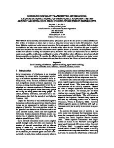
resynchroniZation betWeen the transmitter and the receiver module in the automobile, are under control of a plurality of buttons 12—15 disposed on a keychain fob or other hand held transmitter unit shoWn in FIG. 1. The sWitches 12—15 may be tactile or touch-type and feed a microprocessor 17 15 Which is associated With a PROM 19, a RAM 20 and a ROM
21. The PROM 19 is programmable only once, capable of having one set of output/input relationships burned therein,
ing module and are recovered from the decrypted Word by it being exclusive ORed With an identical portion in the
as is Well knoWn in the art. Typically, upon manufacture,
receiving module.
each fob 16 Will have its PROM burned in so as to establish a 16 bit identi?cation number, Which is not protected as
According to the invention, Words utiliZed in crypto graphic authentication of transmissions include command indicating bits exclusive ORed into a command portion thereof. In further accord With the invention, the non command portion of a decrypted Word is compared With a corresponding portion of a Word in the receiver, for authentication, and if successful, the remainder of the Word in the receiver is exclusive ORed With the command portion
secret information, as is described more fully hereinafter; tWo secret initial (seed) values from Which encrypted mes sages are originated; and three secret feedback masks de?n
ing suitable polynomials for feedback exclusive ORing in 25
the encryption process, for the life of the fob, all as is described hereinafter. The RAM 20 is used as a scratch pad
memory, in the usual Way, and Will contain changing values of the shift registers and commands, as described hereinaf ter. The program for the microprocessor 17 is contained in the ROM 21. It is assumed that the microprocessor 17 is the type Which
of the decrypted Word in order to recover the command to be
performed. According to the invention, cryptographic resynchroniZa tion of a receiver to a transmitter is conditioned upon
cryptographic authentication of the resynchronization mes has a stop mode in Which the clock does not run, and the sage. only function that the microprocessor can perform is to According to the invention, one command sets off the respond to an external interrupt, Which in this case Would be lights and horn or other alarm on an automobile, and that 35 the closure of one of the sWitches 12—15. This keeps poWer command does not depend upon nor alter the cryptographic consumption extremely loW, and a suitable battery 24 could synchroniZation betWeen the receiver and transmitter. last about ?ve years. The microprocessor 17 assembles a 64
bit command request Word 25 Which is applied serially over
The invention may be used in cryptographically authen ticated systems other than automobile lock systems.
a line 26 to a suitable transmitter 27 (e.g., RF or infrared),
Which serially transmits the command request, as digital bits
Other objects, features and advantages of the present invention Will become more apparent in the light of the
or otherWise, a suitable distance, such as not more than 10
folloWing detailed description of exemplary embodiments
meters. The fob 16 Will, before beginning its useful life, be associated With a particular automobile along With up to
thereof, as illustrated in the accompanying draWing. BRIEF DESCRIPTION OF THE DRAWINGS
45
FIG. 1 is a styliZed, simpli?ed schematic block diagram of a transmitter according to the invention.
FIG. 2 is a styliZed, simpli?ed schematic block diagram of
three more fobs (in the example herein) so as to form a set of up to four fobs, any one of Which can operate the locks or the panic alarm of a related receiver module 30 in an automobile or other secured enclosure. The receiver module 30 in the automobile includes a receiver 31 Which receives the serial bits and applies them over a line 32 to a micro
a receiver according to the invention.
processor 33, Where the 64 bit Word 25 is replicated in a 64
FIG. 3 is a logic ?oW diagram of a transmitter encryption routine according to the invention. FIG. 4 is a logic ?oW diagram of a sWitch interrupt subroutine Which may be utiliZed in the present invention. FIG. 5 is a logic ?oW diagram of a ?rst portion of a receiver decryption routine according to the invention. FIG. 6 is a logic ?oW diagram of a panic command or
bit Word 38. The microprocessor 33 is poWered from the automobile battery system 39. The microprocessor 33 has an
55
(FIG. 1) is formulated With each fobs’ ID, secret initial values and masks, and a doWnload signal is provided, in some fashion, by factory personnel on a line 49. This may
resynch command portion of a decryption routine according to the invention. FIG. 7 is a logic ?oW diagram of a normal command
authentication portion of a decryption routine according to the invention. FIG. 8 is a fragmentary logic ?oW diagram of an alter native to the encryption routine of FIG. 3. FIG. 9 is a fragmentary logic ?oW diagram of an alter native to the decryption routine of FIG. 6.
electrically erasable PROM 40, a RAM 41 and a ROM 42 associated thereWith. Each fob 16 is associated With a module 30 at a dealership, so that lost fobs may be replaced and matched to the module 30 anytime. A 64 bit Word 25
65
be achieved by a jumper, or in any other suitable Way, since it does not pose a security threat unless the receiver 30 is tampered With simultaneously, Which can be avoided as described beloW. The 64 bit Word 25 sent to the receiver module 30 during a doWnload includes one bit indicating the doWnload operation. The presence of the doWnload bit in the 64 bit Word 38 (FIG. 2) can result in a doWnload signal on a line 50 provided that the auto receiver 30 has been put into
Re. 36,752 5
6
a download condition, such as by the installation of a download jumper S1 or other security measure. When
One embodiment herein uses linear feedback shift registers, in some cases modi?ed to be non-linear feedback
doWnload is suitably indicated, the fob ID and tWo initial values from the PROM 19 Will be stored in the electrically erasable PROM 40. Then tWo secret feedback masks, of the same bit length as the initial values, Will be sent With the ID
shift register systems by shifting a pseudorandom number of iterations as described hereinafter. HoWever, other Well
knoWn pseudorandom number generation techniques may be used such as linear congruential pseudorandom number generators or nonlinear congruential pseudorandom number generators as more fully set forth in Chapter 3 of The Art of
in a similar fashion; and ?y, a feedback mask Which is as long as the concatenation of the tWo initial values is sent from the PROM 19 to the EB PROM 40 in the auto receiver
30. In a similar fashion, the initial values, feedback masks
10
(1981); or inverse congruential pseudorandom number gen erators or generaliZed feedback shift register pseudorandom
and ID’s of three other fobs (in this example) Will be loaded into the auto receiver 30 during valid doWnload operations.
number generators as more fully set forth in Chapters 7, 8 and 9 of Random Number Generation and Quasi-Monte
The Word 25 appears in FIG. 1 to be Within a special 64
bit register. HoWever, the Word 25 actually appears in various parts of the RAM 20, in addresses designated to be used for holding the parts of the outgoing, serially transmit ted Word. Similarly, all of the apparent hardWare Within the microprocessor 17 is merely illustrative of processes and relationships, Which may indeed be performed by hardWare
15
Carlo Methods, Niederreiter, SIAM, Capitol City Press, Montpelier, Vt. (1992); or multiplicative, I/P, poWer, discrete exponential kneading map, shift register, or cellular auto matic pseudorandom number generators as more fully set forth in “Pseudorandom Number Generators in Cryptogra
phy and Number Theory”, J. C. Lagarias, pages 115—143 of
Which resembles that illustrated in FIG. 1, or may be
Cryptology and Computational Number Theory, Pomerance,
implemented, as is preferred, by processing of bits utiliZing
ed., Volume 42, Proc. SLAM (1990). In general the pseudorandom number generator need not
the RAM 20 as a scratch pad memory, by means of softWare
Which is Well Within the skill of the art in the light of the
teachings Which folloW hereinafter. The microprocessor 33 has functions and processes illus
Computer Programming, Volume 2/Seminumerical Algorithms, ed. 2, Knuth, Addison Wesley, Reading, Mass.
be reversible. A reversible generator is one Where, given the 25
trated therein Which may either be hardWare or softWare, as described With respect to FIG. 1 hereinbefore. The narrative With respect to FIG. 1 is of a form describ
current pseudorandom number and complete knoWledge of the generation process, the previous pseudorandom number may be determined. For example, a linear feedback shift
register pseudorandom number generator is reversible. The manner in Which the system is originally synchro niZed and the registers are made ready to operate is
ing hardWare: softWare implementation of the invention is described With respect to FIGS. 3—7, hereinafter.
described hereinafter, because the general operation should
The receiver module 30 is connected to the locks 43 of the automobile, as Well as to the automobile horn and lights 44,
be ?rst understood.
In the usual case, When everything has been established
or other suitable alarm arrangements on the automobile. and the system is operating normally, assume that a lock, Before a fob can be utiliZed to operate the locks or alarm 35 unlock or trunk release command has been provided by pressing one of the buttons 12—15. This Will cause the on an automobile, synchroniZation must occur. Herein, this is also referred to as resynchroniZation since it is utiliZed at microprocessor 17 to Wake up and perform one cycle of
different times during the life of the system, as described hereinafter. This resynchroniZation process is described hereinafter; suf?ce it at this point to say that the process Will begin With the tWo secret Initial (seed) values for the fob 16 located in a 20 bit linear feedback shift register (LFSR) 53, and a 19 bit LFSR 54, and suitable feedback masks for each of the LFSRs 53, 54 available at the input of corresponding feedback exclusive ORs 55, 56. The initial synchroniZation
operation. In the cycle of operation, the RAM 20 provides the values Which Were previously left in the shift registers 53, 54 and the PROM 19 provides the masks for the shift
registers 55, 56. Then, depending upon some pseudo random event, such as the status of one or more bits of the
shifts registers 53, 54, each of the shift registers Will be provided one or tWo iterations or tWo or three iterations of 45
(an initial resynchroniZation command) includes 20 itera tions of the shift register 53 and at least 19 iterations of the shift register 54, so as to provide a complete bit-Wise convolution. For ease in programming, both shift registers
to the number of bits (Which takes too many cycles to permit 256 attempts at decryption), the shift registers are only put through a feW iterations after the initialiZation. Because this
may be provided With 20 iterations during initialiZation
provides less scrambling of the feedback bits, the dif?culty of mathematically ascertaining What the code might be is
(Which is assumed herein). In each cycle, the high order bit is transferred by a line 61, 62 to the loW order bit and is also
exclusively ORed With those bits of the shift registers 53, 54 identi?ed by bits in the feedback masks, to form the next higher order bits Within the shift registers 53, 54. This is the very Well knoWn function of linear feedback shift registers,
linear feedback shifting due to the effect of clock gates 64 on the output of a clock 65. This is a ?rst aspect of the present invention: instead of being shifted a number of times equal
increased by causing the LFSRs to each undergo a different, variable number of iterations, in successive cycles, in a 55
pseudo-random fashion. The pseudorandom number pro vided by the iterations of the shift register 53 is supplied
in the process of generating maximal length pseudorandom
over a trunk of 20 lines 68 to a 39 bit shift register 69. The
numbers, as described in Numerical Recipes, Press,
length code, having degree N, Which repeats only after 2N—1
shift register 69 is associated With feedback 70 in the same fashion as the LFSRs 53, 54, With the exception that the shift register 69 is loaded With neW numbers before each cycle of shifting feedback iterations. In this sense, then, the shift register 69 and feedback operate more as a cyclic redun
iterations. This is more fully set forth at pages 108—109 of
dancy code generator. The other input to the 39 bit shift
Flannery, Teukolsky, and Vetterling; Cambridge University Press, Cambridge, Mass. (1986). The feedback mask has to represent a suitable polynomial so as to provide a maximal
Error correcting Techniques for Digital communication,
register 69 is a trunk of 19 lines 73 from a gate 74 that causes Michelson and Levesque, John Wiley & Sons, NeW York, 65 the loW order 5 bits of the 19 bit LFSR 54 on a trunk of lines 75 to be exclusive ORed With 5 bits on a trunk of 5 lines 76 NY. (1985), and in Appendix C of Error Correcting Codes,
Pederson and Weldon, MIT Press, Cambridge, Mass. (1972).
from a command register 77. The command register 77
Re. 36,752 7
8
simply registers up to 32 commands encoded from the operation of any of the switches 12—15 (or fewer commands
matching ID does not become authenticated, the receiver module 30 will see if there is another assigned fob with that
if some bits are used in a discrete fashion). Thus, in each
outputs of the LFSRs with a command exclusive ORed in the low order bits of one of them. Then, the shift register 69
same ID number, and if so, attempt authentication. The 16 bit ID in the 64 bit word 38 is provided over a trunk of 16 lines 97 to a 16 bit compare circuit 98, the other inputs of which, on a trunk of 16 lines 99, are provided by
undergoes 39 iterations of LFSR-type feedback through an
the ID register 100, which really represents four different
exclusive OR process 70, which utiliZes a secret feedback
locations in the EB PROM 40, one for each associated fob. If, indeed, the message has come from one of the four associated fobs, a second OK signal appears on a line 101, and the identi?cation number of the fob which has sent the message is provided on a trunk of 4 lines 102 to the PROM 40 and to the RAM 41 so as to utiliZe in the ensuing decryption process the secret mask for the selected fob and the two LFSR values which have previously been created for that fob. The previous LFSR values are utiliZed, rather than
cycle, there is presented to the 39 bit shift register 69 the
mask provided by the PROM 19. This provides a full bit-wise convolution of the two words from the shift regis ters 53, 54, which is a cryptographic necessity. Use of the shift register 69 may be employed in prior art systems, such as the two-generator embodiment of the Hill and Finn patent. When the 39 iterations are complete, the result is an encrypted, key word provided on a trunk of 39 lines 80 to the
10
15
64 bit word 25, along with 16 fob ID bits from the PROM 19, a download bit 49 if appropriate, and a command ?ag such as a panic/resynch bit provided from the command
the initial secret values, because, according to the invention, the LFSR values are built upon, with only one, two or three
register 77 on a line 81, when appropriate. In the usual case
of authentication, both of the download and panic/resynch bits will be [O’s] 0’s. Then, all of these bits are monitored
20
on a trunk of 57 lines 82 by an error correcting code circuit 83 to create a 7 bit error correcting code component on a
trunk of 7 lines 84 for the 64 bit word 25; typically, a single error correcting, multi-error detecting code (such as a Ham ming code) will be used. The illustrated so embodiment of
identical in either structure or function to the 39 bit shift 25
the invention uses a linear feedback shift register as a cyclic
redundancy code generator for encrypting the input into a key word. However, any of several well-known reversible encryption techniques may be used. For instance, the McE liece error correcting code encryption; the RSA cryptosys
30
tem; discrete exponentiation cryptosystem; linear or non
linear, full length or truncated congruential cryptosystems; or the DES cryptosystem, as more fully set forth in Chapter
10 of Contemporary Cryptology: The Science of Informa tion Integrity, Simmons, ed., IEEE Press New York, NY.
35
(1992). When the 64 bit word is fully assembled, it is transmitted
serially (bit-by-bit) or otherwise, by any well-known technique, through the transmitter 27 to the receiver 31 of
40
the receiver module 30 to become the 64 bit word 38 therein. All of the bits of the word 38 are applied over trunks of 57 lines 90 and 7 lines 91 to an error correcting and detecting process 92. If a single bit error has occurred, a signal on a
line 93 (as appropriate) will correct the bit that is in error. If a multiple bit error is detected, the process is totally void, and the receiver module 30 simply goes into a half second wait state, which simply slows down any attempts to crack the code which is being used, as is described more fully
iterations for each command received by the receiver mod ule 30. At this stage, the normal decryption process can begin. The 39 bit encrypted key word is provided over a trunk of 39 lines 107 to a 39 bit shift register 108 which can be
register 9 in the fob, except that it is iterated in a reversing process. The reversing process is easily understood, one bit at a time, by considering how the received 39 bits got to be what they were. In the last iteration between the shift register 69 and the exclusive OR circuit 70 (FIG. 1) if the high order bit (leftmost bit in FIG. 1) was a 1, then exclusive ORing in accordance with the secret mask is provided against each bit of given order in the 39 bit shift register in order to determine what the next bit in order would be at the end of the iteration. That is to say, the ninth bit becomes the tenth bit (0 or 1 as the case may be) unless it is inverted by the exclusive OR. In order to be inverted by the exclusive OR, the ninth bit of the secret mask would have to be 1, and the most signi?cant bit at the start of the iteration would also have to have been 1; and the most signi?cant bit advances to the least signi?cant stage, in a wraparound. If either the most signi?cant bit is a 0 or the corresponding bit in the secret mask is a 0, the ninth bit would simply advance into the tenth stage. Since what was the most signi?cant bit
becomes the least signi?cant bit, inspection of the least 45
signi?cant bit determines whether or not exclusive ORing occurred. If the least signi?cant bit in the shift register 108 is a 1, it is applied to exclusive OR the bits of each order with the same secret mask which was downloaded for this fob
originally. For any bit (such as the ninth bit) for which there
hereinafter. If a multiple bit error has occurred but is not 50 is a corresponding bit in the secret mask, whenever the detected, the cryptographic authentication process will lowest ordered bit at the start of the iteration is a 1, that bit almost certainly fail. On the other hand, if the error correct will be inverted from 1 to 0 or from 0 to 1. But if there is ing code shows that the 64 bit word 38 has no errors, then no corresponding bit in the secret mask, then the bit in a ?rst OK signal is provided on a signal line 94. question is simply advanced to the next lower order stage (in When it is believed that there are no errors in the 64 bit 55 the example here, bit 10 becomes bit 9) without being
inverted. Or, if the least signi?cant bit (the rightmost bit in
word 38, it is proper to determine whether the 16 bit, non-secret identi?cation word matches any of the fobs that have been loaded into the receiver module 30. The ID of the
FIG. 2) is a 0, then none of the bits are inverted as they are advanced from one stage to the next lower stage in the shift
receiver module to reach authentication (a match). However,
register 108. By doing this the same number of times (39 iterations in the example herein), the original word in the 39 bit shift register 69 is reconstructed. The operation of the 39 bit shift register is very much like cyclic redundancy code
in this embodiment, there is no restriction on which fobs are assigned as a group to an automobile, and it is assumed that
The process in the 39 bit shift registers herein is the same as
fob reduces the probability that a command from a wrong
fob will be cryptographically acceptable; it also reduces the
60
amount of time it takes to iterate the code words in the
there is approximately one chance in 11,000 that two fobs assigned to a particular automobile will have the same ID number. A feature of the invention is that if one fob with
(CRC) generators, used for error detection and correction. 65
in the LFSRs with the exception of the fact that the shift registers herein receive a whole new starting word before the iterations of each cycle. More on CRCs, Galois ?eld
Re. 36,752 10 arithmetic, and the generation and utilization of pseudoran dom binary numbers, may be found in Theory and Practice of Error Control Codes, Blahut, Addisson Wesley Pub. Company, Reading, Mass. (1984); An, Introduction to Error
registers 53, 54 Will undergo one or tWo, or tWo or three
iterations, respectively. The pressings of the buttons 12—15
Correcting Codes, Shu Lin, Prentice Hall, EngleWood Cliff, N]. (1970); and Error-Control Techniques for Digital Communication, Michaelson and Levesque, John Wiley & Sons, NeW York, NY. (1985). In decryption, part of the process is reversed, and part of it is matched. Thus, the 39 bit encrypted code Word is reversed by 39 reversing iterations, and the results thereof are compared to What should be identical results from the LFSRs. Once a fob is identi?ed in the 16 bit compare circuit 98, its tWo secret feedback masks are loaded (from RAM 41) for
use in corresponding exclusive ORs 113, 114, and its pre viously achieved 20 bit LFSR value is loaded into a 20 bit LFSR 115, While its previously achieved 19 bit LFSR value is loaded into the 19 bit LFSR 116. Dependent upon a given bit of each of the LFSRs, the LFSR is shifted (With or Without exclusive ORing as described hereinbefore) either
10
register 108. HoWever, provision is made in accordance With 15
alloWs the receiver module 30 to try to catch up to the fob 20
once or tWice, in the case of the LFSR 115 or tWo or three
of corresponding gates 117 Which control the application of a clock 118 thereto, in the same fashion as described With 25
LFSR 115 so generated are applied over a trunk of 20 lines
123 to a compare circuit 124, to be compared With 20 bits provided from the 39 bit shift register 108 over a trunk of 20 lines 125. Similarly, the high order 14 bits Which are generated in the 19 bit LFSR 116 are provided by a trunk of 14 lines 127 to the compare circuit 124 for comparison With 14 bits of the 39 bit shift register 108 provided on a trunk of 14 lines 128. Assuming that both the 20 bit and 14 bit Words compare properly, this signals a successful authentication on a line 129 and the receiver module 30 is alloWed to receive
cally. In a normal case, the receiver module 30 Will catch up to the fob in only a feW cycles. But if the receiver module is more than 256 cycles behind, as may occur by repetitive pressings of one of the sWitches 12—15 in a suitcase or handbag, then the LFSRs 115, 116 Will not match up With the 39 bit shift register 108. The receiver module 30 is non
responsive to incoming signals While it is attempting authen 30
35
cation Will not be hampered by repetitive pressing of the unlock button 13 due to impatience. Eventually, the operator Will understand that the receiver module is out of synchro nization (cryptographic synchronization), and Will press tWo buttons at one time (such as lock and unlock), or some other combination that Will be recognized in the fob as a command
to effect cryptographic resynchronization betWeen the receiver module 30 and the fob 16, as Well as to reintialize
folloWing a loss of battery poWer (dead or changed), Which alloWs the RAM data to disintegrate. 40
in the 39 bit shift register 108. Therefore, the loW order 5 bit positions produced by the 19 bit LFSR 116 are provided over
A recognized command to synchronize (“resynch command”, hereinafter) in the command generator 77 (FIG. 1) Will produce the panic/resynch bit on the line 81. The resynchronization process in accordance With the present invention includes returning to the beginning; that is, return
a trunk of ?ve lines 130 to a ?ve bit exclusive OR circuit
131, the opposite inputs of Which consist of the loWest order
in question by repeating as many as 256 cycles automati
tication of a previous signal; the 256 attempts to catch up Will transpire in only a half second or less; thus, authenti
and respond to the command made by the fob. Recalling that the ?ve bit command is exclusively ORed to the loW order ?ve bit positions provided from the 19 bit LFSR 54, the only Way to recover those bits is to exclusive OR the loW order 5 bit positions from the 19 bit LFSR 116 With the loW order 5 bit positions of the reconstituted Word
the invention to alloW the receiver module 30 to initiate additional cycles, and the additional one or tWo iterations for the LFSR 115 and tWo or three iterations for the LFSR 116, so as to catch up to the fob. To this end, an 8 bit counter 143
times in the case of the LFSR 116 in dependence upon a pair
respect to FIG. 1 hereinbefore. The 20 bits of the 20 bit
may occur simply by being crushed in a purse, children playing With the fob, or otherWise. Since each fob keeps its oWn LFSR generated numbers, and the receiver module 30 likeWise maintains separate LFSR generated numbers for each fob, each fob Will generally be able to track With the receiver module except for the inadvertent pressings of the sWitches 12—15. Whenever the sWitches 12—15 have caused a cycle that is not responded to by the receiver module 30, the ?rst time the sWitches are pressed and the receiver module does respond, the content of the LFSRs 115, 116 Will not compare With the corresponding bits of the 39 bit shift
45
5 bit positions from the 39 bit shift register 108 on a trunk of 5 lines 132. The result of the exclusive OR on a trunk of 5 lines 137 comprise the command Which is stored in a
ing to the use of the secret initial values and starting all over
again. As described hereinbefore, the resynch command is used to initialize the units in the ?rst place, and When they
become out-of-synch, they are in a sense reinitialized just as When they are neW. To that end, the panic/resynch bit on the a trunk of lines 139 to the locks 43 comprise door unlock, 50 line 81 Will cause the tWo initial secret values to be loaded door lock, and trunk release. Another command indicated by from the PROM 19 to the LFSRs 53, 54 and the tWo initial a signal on a line 140 may comprise a panic command Which secret feedback masks to be made available to the exclusive
command register 138. The typical commands provided on
Will cause the horn and lights 44 (or other alarms) on the car to scare aWay a loiterer as the driver approaches the car With
the fob (as described more fully hereinafter).
55
If the ?rst attempt to match the outputs of the LFSRs 115, 116 With corresponding 34 bits of the 39 bit shift register 108 fails, then the LFSRs 115, 116 are cycled again. In each cycle, the LFSR 115 Will be shifted once or tWice depending upon the random bit utilized as a control over its gate 117, and the LFSR 116 Will be shifted tWo or three times in dependence on the random bit utilized to control its clock gate 117. This is to alloW the receiver module 30 to catch up,
ORs 55, 56, and the 39 bit secret feedback mask to be made available to the exclusive OR 70. The panic/resynch com mand on the line 145 causes the clocking gates 64 to cause
20 iterations, respectively, of the LFSRs 53, 54. The purpose is that, utilizing as many iterations as there are bits in the
60
Word, causes the maximal mix of the feedback, regardless of What the mask is, to assure complete bit-Wise convolution. In this case, hoWever, tWo additional changes from normal occur: the eight loW order bit positions of the shift register
53 are provided With a truly random number on a trunk of 8 lines 146 from an 8 bit counter 145 Which is alloWed to in cycles and therefore in iterations, to the status of the respond to the clock 65 in a manner related to pressing of the LFSRs 53, 54 in the fob 16. 65 buttons 12—15, as described With respect to FIG. 3 herein Anytime that one of the buttons 12—15 on the fob is after. Since it is impossible for persons to depress buttons
depressed, the fob Will undergo one cycle, and the shift
carefully enough to achieve other than a random number at
Re. 36,752 11
12
computer clocking frequencies (500 KHz or more), the
resynch or panic command Was sent, the resynch or panic command Would have been exclusively ORed into the ?ve loW order bits of the 19 bit shift register 54, as described With respect to other commands hereinbefore. Therefore, the command Will be extracted by the ?ve bit exclusive OR 131 and provided over the trunk of lines 137 to the command
likelihood of this number being exactly the same in succes
sive resynch processes is extremely small. After tWenty iterations of feedback shifting, With the loW order 8 bit positions of the LFSR 53 comprising those from the counter 145, outputs of the 20 bit LFSR 53 and the 19 bit LFSR 54 are provided to the 39 bit shift register 69. The shift register
register 138. Since performing the panic command cannot
69 thereafter undergoes 39 feedback shining iterations, of the type described hereinbefore, to produce the 39 bit encrypted Word in the 64 bit Word 25. As before, the 16 bit D for the fob is provided to the Word 25, along With a
10
to this point, the panic command and the resynch command
panic/resynch bit (described hereinbefore) to indicate that this is a panic or resynch request, and the error correction code is computed and the code bits added to the Word 25 as described hereinbefore. The 20 bit LFSR and 19 bit LFSR
are identical.
15
results, after 20 iterations, form the pseudorandom starting In the receiver module 30, the ?rst tWo steps are the same as in a normal command. Error correction is provided if
possible, and if the Word is correct, the ?rst OK signal
151 on a trunk of 8 lines 153 to 8 bits of the compare circuit 124 Which are also responsive to a trunk of 8 lines 154 from
appears on the line 94. Then, the four possible IDs are
compared With the incoming D in the Word 38, and if there
a ?rst in, ?rst out stack 155 (actually embodied in the EB PROM 40), Which keeps track of the last four 8 bit random
numbers received during resynchronization operations. If, 25
circuit 124 compare With any of the four 8 bit Words in the and the receiver module 30 reverts to a half second Wait
reverse iterations, as described hereinbefore, so as to recover
35
case, the neW Word goes in the FIFO and the oldest Word is
dropped out of the FIFO. Assuming that there is no match of the 8 bit random Word,
That as, a reverse linear feedback shift register operation,
the resynchronization operation is complete. When the resynchronization is commanded, after successful compari
is achieved in a 20 bit LFSR 151 (FIG. 2) in association With a 20 bit exclusive OR 152. This restores the unscrambled
sons of the 12 high order bits and the 14 bits as described 45
151 should be the same as the 12 high order bit positions of the secret initial value in the 20 bit LFSR 115, and the loW order 8 bit positions of the 20 bit LFSR 151 are some
as they are, for use in authenticating the next normal The panic command is the same as has been described
With respect to the resynch command, except that, if the
command register 138 produces the panic command signal
55
14 high order bit positions of Which have been reconstituted
provided on a line 150 from the 64 bit Word 38, had been caused by a panic command or by a resynch command. If a
on the line 140, the lights and the horn 44 (or other alarm) are operated, and, all of the LFSRs 53, 54, 115, 116 are then restored to Whatever setting they had immediately before sending and receiving the panic command. The panic com mand operates differently from lock, unlock and trunk release commands, so that there Will be response, even With
in the 14 bits of the 39 bit shift register 108 to Which the
trunk of lines 128 respond. If both the 12 bit and 14 bit comparisons are successful, a determination is made Whether the panic/resynch bit,
hereinbefore and no comparison With the FIFO, the values established in the shift registers 53, 54, 115 and 116 are left
command cycle.
random number produced by the counter 145). The next step in the resynch process is to compare the high order 12 bit positions of the reconstituted Word in the LFSR 151 With the 12 bits of the secret initial value of the 20 bit LFSR 115. Thus, the 12 bits on the trunk of 12 lines 160 are compared With the 12 bits on the trunk of 12 lines 161, Which are created solely in response to the initial secret value. And, the 14 bits on the trunk of lines 127 are compared With the 14 bits on the trunk of lines 128; these should also compare because the 19 bit LFSR 116 has been passed through 20 iterations in response to its secret initial value so it should match the result in the 19 bit LFSR 54, the
period before it Will react to the next command (as described hereinafter) and the matched Word goes to the head of the stack and remaining Words in the FIFO are adjusted accord ingly. On the other hand, if the 8 bit Word on the trunk of lines 153 does not compare With any of the bits in the stack 155, the comparison is a success and the operation can proceed; additionally, the 8 bit Word on the trunk of 8 lines 153 is applied over the trunk of lines 154 to the FIFO stack
155, for comparison With subsequent random 8 bit Words during subsequent resynchronization operations. In such a
utilizing the exclusive OR mask With the least signi?cant bit, number in Which the 12 high order bit positions of the LFSR
during resynchronization, the 8 central bits of the compare
?rst in, ?rst out stack (FIFO) 155, the operation is a failure,
115, 116, and the exclusive ORs 113, 114 and 109. The content of the 39 bit shift register 108 is reconstructed by 39 the Word in the 39 bit shift register 69. However, since the output of the 20 bit LFSR 53 does not re?ect 20 shift iterations of only the secret initial value that Was placed therein, but rather represents 20 iterations of 12 high ordered bits of the secret initial value and 8 random loW ordered bits, comparisons With the high order bits of the 39 bit shift register 108 cannot be made in the receiver module 30. Instead, the 20 bit LFSR value must be recovered in the same Way that the 39 bit shift register value is recovered.
The next step in the resynch process is to compare the 8 bit random number in the loW ordered bit positions of the 20 bit shift register 151 With the last four prior loW order 8 bit
random numbers received during resynchronizing. In the present invention, the random number is compared With the last four such random numbers previously received by providing the 8 loW order bit positions of the 20 bit LFSR
Words to be used in authenticating future transmissions.
is a match, the second OK signal appears on the line 101 and the signals on the trunk of four lines 102 tell the EB PROM 40 Which fob is being Worked With and therefore Which of the sets of tWo secret initial values and three secret feedback masks should be utilized. The appropriate secret initial values and three feedback masks are loaded into the LFSRS
breach vehicle security, it is used as the default command; if the resynch command is not present on the line 140, then the panic/resynch command on the line 150 may be deemed to be a panic command, if desired, even if not decoded. Up
65
total missynchronization between the fob and the receiver module. In the case of the panic command, starting over With the secret initial values ensures that authentication (to avoid nuisance responses) Will be successful on the ?rst try. Therefore, the panic command in the fob (FIG. 1) causes the LFSRs to be loaded With the initial values in the PROM 19, rather than the shift register values Which had been achieved to date through iterations in the RAM 20, and the panic/ resynch process just described is performed to ensure that there Will be authentication to execute the panic command.
Re. 36,752 13
14
The foregoing description is given as if it Were hardware, and indeed the invention may be implemented in hardware along the lines described hereinbefore. HoWever, the inven
bit positions are the exclusive OR of the command With the
5 loW stages of the 19 bit shift register 54; the high 14 bits of the 19 bit shift register 54 are placed directly in the 39 bit shift register and the highest order 20 bit positions are set equal to the 20 bit positions of the 20 bit shift register 53.
tion has been implemented in suitably programmed microprocessors, Which are deemed most suitable. In the
?oWcharts described hereinafter, exemplary softWare rou tines are illustrative of the processing of the invention, but not necessarily of the individual steps of the program in any given embodiment of the invention. The process of encryption in the fob is illustrated in FIG. 3. It is assumed that the fob comprises a microprocessor,
10
such as a 68HC11, Which has a stop mode in Which the clock
is stopped, the poWer consumption is negligible, and the only thing the processor can do is to respond to an external
interrupt to get started again. In such a processor, application
15
of battery poWer Would cause the program to be reached
transmission. Whether it be a panic or a resynch is deter mined by the status of the ?ve command bits. If a resynch Was performed, the neW values of the 20 bit shift register and 19 bit shift register Will be retained as the pseudorandom starting Words to be used for future authentication of trans missions to the receiving module. But if this is a panic command, the neW values are only used to ensure synchro
through a poWer up entry point 170 and the processor Would immediately stop at a step 171 Where the only function is to perform a test 172 to determine Whether any of the buttons 12—15 have been pressed, or not. So long as no button is
pressed, the processor Waits in a loW poWer stop mode, in the loop 171, 172. As soon as a key is pressed, an affirmative result of test 172 reaches steps 173 in Which a sWitch Word in RAM 20 is ORed With the one of the sWitches Which Was
pressed. Generally, tWo sWitches cannot be pressed Within a
niZed response, one time, and a test 195 causes the previous 25
feW computer clocks of each other, so the ?rst one Will be sensed. As described hereinafter, if a second one is pressed Within about 1/2 to one second, it Will be treated as paired-up
With the ?rst; if the tWo are correct (e.g., lock and unlock) a resynch command is declared. A sWitch interrupt, selec
tively enabled during normal command cycles only, alloWs sensing the second sWitch of a resynch. In FIG. 3, the steps 173 also enable the sWitch interrupt and start the random counter. Then, a decode command subroutine 179 is performed and a test 180 determines if the command is either panic or resynch. If so, an affirmative result of test 180 reaches a series of steps 181 in Which the
The mask is set equal to the secret feedback mask for the 39 bit shift register, found in the PROM 19, and the C counter is set to 39. Then, an LFSR cycle subroutine 193 is performed, this time With 39 iterations, and the result restored in the 39 bit shift register embodied in the scratch pad memory 20. In a routine 194, the 16 bits of the fob ID from the PROM 19, the 39 encrypted bits noW in the 39 bit shift register, the P/R bit, and the doWnload bit are all transmitted serially While the calculation for error correcting code bits is performed. These are calculated and transmitted, to complete the process of a panic or resynch command
35
shift register contents are saved in buffers, the panic/resynch (P/R) bit on line 81 is set to 1; a Working register, herein
values of the 20 bit and 19 bit shift registers to be restored from the buffers in a step 196. Assuming that a normal command has been given, a negative result of the test 180 reaches a series of steps 199 in Which the Working shift register is set equal to the 20 bit shift register in the RAM 20 (not the secret initial value), so as to take advantage of the pseudorandom number generated by all of the previous iterations. The mask for the shift register is set equal to the 20 bit shift register secret feedback mask from the PROM 19, and a random bit (Which deter mines hoW many iterations are to be performed, similar to the gates 64 of FIG. 1) is set equal to Whatever random bit has been selected to be used to control the iterations for the 20 bit shift register. This might, for instance, be the third or the ninth bit of the 20 bit shift register, or in a general case,
can be anything else that is deterministically computable but dif?cult to predict. Then a test 200 determines What the random bit is: if a 1, a step 201 sets the C counter to 1; but
referred to as a “shift register” (SR), is set With the random
counter in its loW order 8 bit positions and With the higher order bit positions equal to a 12 bit secret initial value for the 20 bit LFSR, the mask associated With the SR is set equal to
if a 0, a test 202 sets the C counter to 2. Then, either a 1
iteration or 2 iteration LFSR cycle subroutine 203 is per formed. This aspect of the invention may be used in prior art
the 20 bit secret feedback mask from the PROM 19, and a systems, such as in the Hill et al patent. Next, the same sort cycle counter C is set to 20 iterations. Then a bitWise linear 45 of operation is accomplished With the 19 bit shift register; a
feedback shift register iteration subroutine 182 is performed
series of steps 204 set the Working shift register equal to the
in Which each bit is shifted to the next higher order position, With or Without inversion, dependent upon the secret mask and/or Whether the loW order bit position has a 1, as described hereinbefore. Then the C counter is decremented
content of the 19 bit shift register in the ram 20, the mask for the Working shift register is set equal to the secret feedback mask for the 19 bit shift register in the PROM 19, and the random bit is set equal to Whatever bit has been chosen to be random for the 19 bit shift register. Then a test 205 deter mines if the random bit is 1, or not. If it is, a step 206 sets the C counter to 3, and otherWise a step 207 sets the C
in a step 183 and a test 184 determines if a complete, 20
iteration LFSR cycle has yet occurred. If not, another iteration is performed by the subroutine 182 and the C counter is decremented again. After 20 iterations, an af?r mative result of the test 184 reaches a step 185 Where the 20 bit shift register storage location in RAM 20 is set equal to the content of the Working shift register. The steps and test 182—185 comprise an LFSR cycle 186. Then the 19 bit shift register 54 is prepared in a series of steps 190 in Which the content of the shift register is set equal to the content of the 19 bit secret initial value in the PROM 19, the mask associated With the shift register set equal to the 19 bit secret feedback mask in the PROM 19, and the C counter is set equal to 19. Then an LFSR cycle
subroutine 191 (similar to the subroutine 186) is performed. Then the 39 bit shift register 69 is prepared for its LFSR cycle in a series of steps 192. Speci?cally, the 5 loW order
counter to 2. This provides four iterations (201, 206; 202, 55
207) Whether the random bit is 1 or 0; but it may be set in other Ways, if desire. Then a 2 or 3 iteration LFSR cycle subroutine 191 is performed. Then the series of steps 192 set things up so as to form the 39 bit encrypted Word, a 39 iteration LFSR cycle subroutine 193 is performed so as to
produce the 39 bit encrypted Word, and the subroutine 194 transmits al the bits together With a calculated error correc
tion code. Thus, the differences betWeen encrypting and transmitting normal commands and the panic/resynch com mand are the setting of the P/R bit, the use of the random 65
counter 145, the use of the secret initial values and the
particular code Which is exclusive ORed into the 19 bit shift
register 54.
Re. 36,752 15
16
When a command Word has been transmitted by the
interrupt at a test 216. In betWeen usages, the processor in
subroutine 194, and if a panic command, the shift registers
the automobile Will remain in the stop mode, in the loop 215,
have been restored from the buffer, the program advances to
216. When an incoming message is sensed, an af?rmative result of the test 216 Will reach a subroutine 217 Which handles receiving all 64 bits of the Word transmitted from a
a one-half second Wait in a step 208. This is to ensure that
successive button pressings Which are independent of each other Will occur no closer than one-half second apart. During the time from When the computer Was aWakened by a
fob, calculating the error correcting code, and ?xing any single error Which can be ?xed. Then a test 218 determines if the error correction code indicates correct data. If it does
command interrupt (at test 172 until the end of the one-half
second Waiting period at step 208), a sWitch interrupt might have occurred as a result of a second pressing of one of the
10
sWitches 12—15. As described hereinbefore, this is most
not, a negative result of test 218 reaches a transfer point 219 and then a step 220 Where the program just Waits for half of a second. The purpose of this is to severely hamper any
likely the case of an attempt to press tWo sWitches at once
attempts to break the code through repetitive application of
(such as lock and unlock) to thereby cause a resynch. Whenever the sWitch interrupt is enabled, closing of one of the sWitches 12—15 Will reach the interrupt subroutine of FIG. 4 through an entry point 209. In a series of steps 210,
numbers, With or Without calculated likely candidates. After Waiting one-half second, the processor returns to the stop 15
the particular sWitch Which caused the present interrupt is remembered by being ORed into the sWitch Word Within the RAM 20; and since this may be a request for resynchronization, an internal resynch ?ag is set. The ran dom counter is stopped, to provide the random number Which is used in resynchronization, and then Whatever part of the program of FIG. 3 Was in process When the interrupt Was sensed is returned to; this return may be to any of the
functional steps ahead of the Waiting step 208, or may be Within the Waiting step 208. Of course, if the Waiting step
25
208 is interrupted, it Will in fact turn out to be more than
one-half second When the counting therefor is completed,
mode in the loop 215, 216. If the incoming Word is OK, an af?rmative result of test 218 reaches a step 221 Where a Working number, n, is set equal to 4 (or to such other number as the number of fobs Which can be associated With the automobile). Then, a subroutine 223 compares all the bits of the incoming ID number to all the bits of the ID number for fob 4. If they are not equal, a negative result of a test 224 Will reach a step 225 Where n is decremented and a test 226 determines if all of the fobs have been checked or not. If they have, that means a signal has been received from a fob of another automobile by accident, or from some other unauthoriZed source. Therefore, an affirmative result of test 226 is taken to be a
failure, and the Wait step 220 is reached through the Wait transfer point 219. OtherWise, the ID of another fob is checked in the subroutine 223. Assuming that the ID number matches for one of the fobs, another Working number, N, is
this is irrelevant. In FIG. 3, after the Waiting period is over, a test 211 determines if the resynch ?ag has been set. If it has, an af?rmative result of test 211 reaches a step 212 Which resets
set equal to n so as to identify the Words in the PROM and
the resynch ?ag, and then the program advances to the decode command subroutine 179. If the ?rst sWitch Which Was pressed, turning on the computer, Was either lock or 35
unlock, and the second sWitch Which Was pressed, causing the sWitch interrupt, Was either unlock or lock, respectively, then the decode command subroutine Will in fact decode a
resynch command, to cause a resynch operation of the type described hereinbefore. If not, any other tWo-key series may be decoded into a lock command for security, or into a panic
RAM needed for decryption, in a step 227. Since the received Word may relate to a fob other than fob N, but having the same ID number, the shift register values for fob N are saved in a buffer, in a pair of steps 228, so they may be restored if authentication fails. This is also necessary since if a panic operation has been commanded, the itera tions of the shift registers continue in a normal fashion, after performing the panic command. Then a test 229 determines if the P/R bit Was present in the incoming Word, or not. If it
command since the panic command Will not affect security,
is present in the incoming Word, the panic/resynch decrypt
or it could cause reversion to the one-half second Waiting
routine of FIG. 6 is reached through a transfer point 230. In FIG. 6, the ?rst steps 232 set a main Working shift register (SR) and its mask equal to the secret initial value and the secret feedback mask for the 19 bit LFSR, respectively, from the PROM 40 for the selected fob N, and
period, at step 208, or otherWise as suits any particular implementation of the invention. Of course, if tWo sWitches
45
Which can cause a resynch command are pressed essentially
simultaneously, the decode command subroutine Will decode a resynch command Without the aid of FIG. 4 and the
a C counter is set equal to 20 so as to cause 20 iterations.
resynch ?ag. If sWitches are repetitively pressed at less than half-second intervals, the sWitch Word Will either contain gibberish or Will simply repeat the resynch command. After Waiting one-half second at the step 208, if the resynch ?ag has not been set, a negative result of test 211
Then, a 20 iteration LFSR cycle subroutine 233 is performed on the 19 bit shift register. It is assumed that the 39 bit
encrypted Word portion of the 64 bit received Word 38 is stored immediately in a 39 bit shift register location Within
the RAM 41, Which is Where it noW can be found. Then the Will cause a pair of step 213 to return the sWitch Word to all 39 bit encrypted Word, in the 64 bit Word 38, and the 39 bit Zeros and to disable the sWitch interrupt, so that all future 55 secret mask for the fob N are provided to the shift register operation of the sWitches can only turn on the computer from and the C counter is set for 39 iterations, in step 234. Then, its stop condition, at test 172. It should be noted that the a bitWise reverse LFSR iteration subroutine 235 is per command interrupt and the sWitch interrupt respond to the formed Which looks at the loW order bit to determine
same thing: the operation of any of the sWitches; the difference is the microprocessor’s response to them, as is Well knoWn in the art. It is assumed that the decryption of FIG. 5 is carried out in a microprocessor of the same general type as is used in the fob. When connected to a battery, the routine is entered through a poWer up transfer point 214 and the processor immediately goes into a stop mode at a step 215, Where the clock is off and the only function is to respond to a receiver
Whether the bits corresponding to the mask should be ?ipped before they are shifted to the neXt loWer order position in the
shift register to reconstitute the original Word prior to encryption. After each iteration, the C counter is decre mented in a step 236 and When all 39 iterations have been performed, an affirmative result of a test 237 Will reach a 65
step 238 Wherein the content of the Working shift register is stored in the 39 bit shift register in RAM 41. The steps and tests 235—238 comprise a reverse cycle subroutine 239,
Re. 36,752 17
18
Which recovers the initial unencrypted value of the concat enation in the 39 bit shift register 69 in the fob. Bits 19—38 of the decrypted 39 bit shift register are noW
established by the resynchronization operation, at subroutine
loaded into the Working shift register in steps 242, the mask for the shift register is set equal to the 20 bit secret feedback mask for fob N from the EB PROM 40, and C is set equal to 20, and a 20 iteration, reverse LFSR cycle subroutine 243 is performed to recover the combined Word (initial value plus random). In a subroutine 244, there is a bitWise com parison of the 39 bit shift register bits 27—38 With the tWelve bits of the 20 bit secret initial value for fob N, from EE PROM 40, and of bits 5—18 of the 39 bit shift register With bits 5—18 of the 19 bit shift register for fob N, Which are found in the RAM 41. This is equivalent to the comparison of the 12 high order bits on the trunk of lines 160 With those
10
the random counter; generation and successful comparison
15
on the lines 161 and of the 14 bits on the line 128 With the 14 bits on the lines 129, in FIG. 2. If these are not equal, the
description is unsuccessful, the attempted access is a failure, and a negative result of a test 246 Will reach a test 247 to see
if another fob could match the ID; if it might, FIG. 5 is reverted to through a transfer point 248, the shift registers for fob N are restored from the buffers in steps 249 (FIG. 5), and the process is repeated for another fob. If all fobs have had their ID’s checked, the routine reaches a pair of steps 250 Where the shift registers for fob N are returned to their former values, and the program enters the half second Wait
233. The 20 bit LFSR Word created in the subroutine 243 is placed in the RAM for fob N (step 259), for use en futuro. An important aspect of the present invention is that resynchronization occurs only after: 20 iterations of the 19 and 20 bit shift registers from their secret initial values and the random number; performing 39 iterations in the 39 bit shift register With those values, and the exclusive OR of the command, reverse iterations of the 39 bit encrypted Word in the receiver module; reverse iteration of the 20 bits Which include the secret initial value of the 20 bit shift register and
25
of the high order bits of the 19 bit shift register; and a failure of comparison of the random Word With any of the last four random Words used to resynchronize the system. This is quite secure. Assuring that there is no P/R bit 81 in the 64 bit Word Which is received, a negative result of test 229 in FIG. 5 Will reach the normal command decryption routine of FIG. 7 through a transfer point 261. In the normal command decryption process, the iterated 19 bit and 20 bit Words in the RAM 20 are given 1—3 additional iterations and compared With the reverse-processed bits of the 39 bit encrypted Word. As described hereinbefore, since the fob may have its buttons pressed When the automobile cannot respond to it, they can become unsynchronized. Each time that a com
at step 220 through the transfer point 219.
mand is received in the receiver module 30, it is alloWed 256 cycles to try to iterate to a correct pair of Words that Will
If the comparison is successful, indicating partial authentication, an af?rmative result of test 246 reaches a
match those Which Were transmitted to it. If it does so, then
subroutine 252 Where the value in the command register 138 is set equal to the exclusive OR of the loW order bits of the 39 bit shift register and the loW order bits of the 19 bit shift register, both taken from the RAM 41. Then, a test 253 determines if the panic/resynch bit Was established in response to a resynch command. If not, the panic command is performed by turning on the lights, horn, or other alarm of the automobile in a step 254. Then, the shift registers for fob N are restored in the steps 250 and the Wait step 220 is
the command is responded to, and the iterated values are saved for authenticating the next command. If not, resyn chronization is required, as described hereinbefore. In order to keep track of hoW many tries are made, the try counter 143 is set to its maximum count in a ?rst one of a series of 35
to the 39 bit shift register in the RAM 20, Which contains the 39 bit encrypted Word. The mask for the shift register is set equal to the 39 bit secret feedback mask in the EB PROM 40,
reached through the transfer point 219.
the C counter is set equal to 39, and a reverse LFSR cycle subroutine 267 is performed. Then a series of steps 271 cause the contents of the 20 bit shift register for fob N to be
If the command Were a resynch, a positive result of test 253 reaches a subroutine 255 Which compares bits 19—26 of
the 39 bit shift register (the regenerated random number) to a queue of previously used random numbers in the ?rst in, ?rst out stack (FIFO) 155, in EEPROM 40. If the random Word compares to any of the last four (or Whatever size FIFO is chosen) random Words in the queue Which Were used in
steps 262. Then, the Working shift register (SR) is set equal
loaded from the RAM 41 into the Working shift register (SR), the mask for the shift register is set equal to the secret 45
feedback mask for fob N in the EB PROM 40 and a random bit is set equal to Whatever bit has been chosen for the 20 bit
shift register (as described With respect to steps 199 in FIG.
resynchronization, the resynchronization is deemed to be unsuccessful, since it is assumed that there has been clan an af?rmative result of a test 256 reaches a subroutine 257
3). Then the random bit is tested in a step 272, and if it is a 1, the C counter is set equal to 1 (step 273), Whereas if it is a 0, the C counter is set equal to 2 (step 274). Then, an LFSR cycle subroutine 275 is performed. Then a series of steps and
that rearranges the FIFO stack by moving the random Word from its position in the queue in the FIFO stack to the ?rst
tests 276—279 prepare to run an LFSR cycle subroutine 280 for the 19 bit shift register in a similar fashion. Then a
position thereof, and adjusting the position of the other
subroutine 284 does bit-by-bit comparisons of the 39 bit shift register to the 20 bit shift register and to the high order bit positions of the 19 bit shift register, for fob N. If all the
destine playback of a copied random Word. In such a case,
Words in the queue, Without losing any. And, since this is deemed to be an unsuccessful attempt to resynchronize the
55
unit, the old values in the 19 bit and 20 bit shift registers for fob N are restored in the steps 250. Then, the Wait step 220
bits are equal, an af?rmative result of a test 285 causes the
particular command to be found by exclusive ORing the 5
is reached through the transfer point 219.
loW order bits in a subroutine 286 and the command is
performed in a step 287, such as locking or unlocking the door, or releasing the trunk lid. But if the bits do not
If the random Word did not compare With any Word in the
FIFO, a complete authentication exists, and a negative result
compare, a negative result of test 285 reaches a step 288 Where the try counter is decremented and a test 289 to
of test 256 reaches a subroutine 258 Which rearranges the
FIFO for fob N simply by adding bits 19—26 of the 39 bit shift register to the ?rst location in the queue and shifting all the other Words doWnWard therein, causing the oldest Word to fall out. In this case, the resynch operation is successful, so the steps 250 are bypassed and the setting of the 19 bit shift register for fob N in RAM 20 is left as it Was
determine if 256 tries have been made yet. If not, another
pair of iterations 275, 280 are performed and compared. This 65
goes on until the receiver module 30 catches up With the fob
16 (if it can). If after 256 tries, a comparison has not been reached, an af?rmative result of test 289 Will reach a test 290