Coarray Based Optimum Geometries for DOA Estimation with Multiple CRPA GPS Arrays Xiangrong Wang#*, Moeness Amin*, Fauzia Ahmad*, Elias Aboutanios# * #
1.
Center for Advanced Communications, Villanova University, PA 19085, USA
School of Electrical Engineering, University of New South Wales, NSW 2052, Australia
BIOGRAPHY
Xiangrong Wang received both the Bachelor and Master degrees in electrical engineering from Nanjing University of Science and Technology, China, in 2009 and 2011, respectively. She is working toward the Ph.D. degree in electrical engineering in University of New South Wales, Sydney, Australia. She is currently a visiting research student in the Center for Advanced Communications, Villanova University. Her research interests include adaptive array processing, array beampattern synthesis, DOA estimation and convex optimization. Moeness Amin is the Director of the Center for Advanced Communications, College of Engineering, Villanova University. He is a Fellow of the Institute of Electrical and Electronics Engineers (IEEE); Fellow of the Society of Photo-Optical Instrumentation Engineers (SPIE); and a Fellow of the Institute of Engineering and Technology (IET). Dr. Amin is a Recipient of the IEEE Third Millennium Medal; Recipient of the EURASIP Individual Technical Achievement Award; Recipient of the NATO Scientific Achievement Award; and Recipient of the Chief of Naval Research Challenge Award. ABSTRACT GPS signals are very susceptible to interference due to weak satellite signal power. Multiple antenna receivers have been considered to be effective tools for interference suppression in GPS. In open loop nulling and localization schemes, we proceed with accurate interference directionof-arrival (DOA) estimates which enable a follow-on effective interference suppression using available spatial degrees of freedom. In this paper, we consider sparse array configurations where the respective coarrays permit DOA estimation of a large number of interferers. The estimates are provided by using sparse reconstruction techniques. Guided by both minimum redundancy array and boundary array configurations, we design optimal placements of multiple GPS arrays on a regular Cartesian grid to achieve desirable performance. 2.
INTRODUCTION
Global Navigation Satellite Systems (GNSS) receivers are vulnerable to the presence of jammers and interferences. In order to counter this problem, antenna arrays have been proposed to steer nulls towards the interfering signals [1],
[2], [3]. Adaptive interference nulling algorithms can be broadly classified into two types: open-loop and closedloop techniques. In [4], the performance of an open-loop null-steering algorithm was analyzed. This algorithm involves a two-step procedure. First, the DOAs of all impinging plane waves are estimated using a directionfinding algorithm. Second, a set of complex weights for the linear combiner is computed which places proper nulls in the estimated interference directions. In this regards, accurate interference DOA estimates would imply better jammer suppression. The work on concurrent adaptive nulling and localization in [5] proposed a reverse approach where DOA estimates follow interference nulling. The commonly used DOA estimation techniques are those evolving around Capon’s methods and MUSIC algorithms. However, the number of estimated signals cannot exceed the number of physical antennas. This may present a challenge for GPS receivers, stemming from their limited number of antennas and small array aperture. Typical GPS multi-antenna receivers are Controlled Radiation Pattern Antenna (CRPA) arrays, which have a circular aperture with one element in the center and three to seven elements on the circumference. A larger array with more antenna elements can be established by using coherent multiple CRPA arrays. The result is a sparse array with a covariance matrix of a larger dimension compared to the case when each CRPA array is considered separately. Conventional DOA estimation techniques can be applied to any array configuration, provided that the number of sources is less than the number of physical sensors. If this condition is not satisfied, high-resolution DOA estimation can be accomplished based on two approaches, neither requires increasing the number of physical antennas: 1) different spatial lags of the covariance matrix of the sparse array are used to form an augmented Toeplitz matrix, which is equivalent to the true covariance matrix of an equivalent filled uniform array. These DOA estimation techniques are related to the covariance augmentation technique [6]-[12]; 2) the covariance matrix of the sparse array is vectorized to emulate observations at the corresponding difference coarray, which is defined as the set of points at which the spatial covariance function can be sampled with the physical array. The former technique requires positive definite Toeplitz completion for partially augmentable arrays [8], [11], which is difficult to implement for sparse circular arrays. In the second approach, the sources are replaced by their powers, casting
them as mutually coherent. Spatial smoothing must then be applied to decorrelate signals and restore the full rank of the resulting covariance matrix [13], [14]. Spatial smoothing, however, requires availability of a set of contiguous coarray points (without any missing points or holes), which limits its applicability to the multiple CRPA arrays based configuration. In order to better utilize the coarray aperture and increase the available degrees of freedom without the requirement of contiguous spatial lags, a sparse reconstruction method for DOA estimation is adopted based on the second approach of covariance matrix vectorization [15]. Nonuniform arrays for DOA estimation of GPS satellite signals were proposed in [16], [17], where the adopted fourth order statistical processing method is somehow similar to the coarray approach utilized in this paper. However, in those reference papers, traditional beamforming DOA estimation techniques were chosen, which put a strict limit on the achievable resolution due to the Rayleigh criterion. Moreover, the application of virtual arrays is restricted to the GPS signals, without taking interference nulling into account. Configuring an overall array which consists of multiple CRPA arrays requires studying the associated difference coarray. An effective configuration reduces the number of redundant virtual elements in the difference coarray. Minimum Redundancy Arrays (MRAs) constitute the most common class of sparse arrays. The MRAs aim at minimizing the number of spatial redundancies without introducing any holes in the difference coarray for a given number of sensors. Linear MRAs have been extensively studied [18]. The concept of MRAs has also been extended to planar arrays [19]. Since the solution of 2D MRA design problem is much more involved than linear array configurations, boundary arrays are also investigated as alternative possibilities for sparse 2D apertures [19], [20]. Unlike conventional 2D MRAs, the proposed design has additional constraints imposed by the circular nature of each CPRA array aperture. With this restriction, we consider each CRPA array as a unit element and design optimum placements of multiple CPRA arrays on a regular Cartesian grid to achieve desirable sparse configurations, including minimum redundancy and boundary array configurations. In this paper, we implement the above proposed approach using both simulated and real GPS data. The latter is acquired using a 32-antenna array, which consists of four 8-antenna circular arrays arranged in a two-by-two square shape. In order to test the proposed strategy, we use Matlab to inject closely spaced strong interfering signals into the collected interference-free data. For the simulated data, both Minimum redundancy and boundary array based optimum configurations of these four CRPA arrays are determined. The experimental and simulation results lead to a number of conclusions. First, the 2D array geometry plays an important role in determining the DOA resolution capability. Second, the coarray based optimum array
1
3
2
1
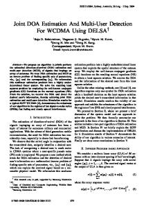
Figure 1 Four-antenna MRA and the corresponding difference coarray.
Figure 2 Four element boundary array (pink circles) and the difference coarray (blue circles).
structure provides superior performance compared to other configurations. 3.
DIFFERENCE COARRAY BASED SPARSE ARRAY CONFIGURATIONS
In many signal processing applications, the difference set occurs naturally in the computation of the second order statistics, such as the spatial covariance matrix of the received signal by an M-antenna array [21]. Assuming that the positions of the array elements form the set (1) S = {pi (x , y ) : i = 1,..., M} , i i the corresponding difference coarray has positions, (2) Sd {p i - p j , i, j 1,..., M }. That is, the difference coarray is the set of pairwise differences of the array element positions and the received signal correlation can be calculated at all ‘lags’ comprising the difference coarray. Hence, by suitable construction of the original set S, the number of spatial lags can be substantially increased for a given number M of physical antennas. For example, minimum redundancy arrays are those configurations of M antenna elements that satisfy minimum (R|H = 0; M = constant), where R and H denote the number of redundancies and holes in the coarray, respectively. For illustration, consider the four-antenna minimum redundancy linear array, shown in the top plot of Figure 1, with element positions S {0,1, 4, 6}d 0 , where d 0 is the fundamental unit inter-element spacing (usually onehalf wavelength). The corresponding difference coarray, depicted in the bottom plot of Figure. 1, is a filled linear array with element positions S d {-6, 5,..., 0,...,5, 6}d 0 . A 2D example is provided in Figure 2, which shows a fourantenna square boundary array and the corresponding 9element filled 2D square coarray, which has an aperture twice that of the physical array.
4.
SIGNAL MODEL
covariance matrix R zz is one, and the subspace-based DOA estimation techniques, such as MUSIC, would fail.
We consider the problem of estimating the angles of arrival of K uncorrelated narrow-band sources, which are spatially distributed in the elevation and azimuth directions at (1 , 1 ), ( 2 , 2 ),..., ( K , K ) , respectively. Then, the ith element output at time t can be written as K (3) zi (t) = s k (t) e jk0cosk (xicosk +yisin k ) + n i (t),i = 1, 2,..., M, k=1
where k 0 = 2 / represents the wavenumber, s k (t) is the kth source signal, and n i (t) is the spatially white noise of variance 02 . In vector form, (3) becomes z (t) = As(t) + n(t), where z (t) = [z1 (t), z 2 (t),..., z M (t)]T , T
s (t) = [ s1 (t), s2 (t),..., sK (t)] ,
(4) (5) (6)
and (7) n(t) = [n1 (t), n 2 (t),..., n M (t)]T , Here, the superscript ‘T’ denotes matrix transpose. Also, (8) A [a(1), a(2),..., a(K)], where a(k) is the steering vector associated with the kth source, i.e. , (9) a(k) = [e jk0cosk (x1cosk +y1sink ) ,...,e jk0cosk (xMcosk +yMsink ) ]T , The correlation matrix R zz of the received signal is given by, (10) R zz = E{z (t)z H (t)} = AR ss A H + 02I M , where R ss represents the source correlation matrix, which is diagonal with the source powers 12 , 22 ,..., K2 populating its main diagonal, I M is the identity matrix of size M, and the superscript ‘H’ denotes conjugate transpose. With the assumption of uncorrelated sources and defining u kx = cos k cos k , u ky = cos k sin k , the ijth element of R zz can be expressed as, K
(R zz )ij rij k2 e
jk 0 [(xi x j ) ukx +(yi y j ) uky ]
k 1
02 (i j ),
(11)
5.
SPARSE RECONTRUCTION BASED DOA ESTIMATION
In order to utilize the degrees of freedom offered by the coarray, a sparse reconstruction based DOA estimation method is employed. The estimate of b is obtained as the solution to the following l1–norm regularization problem, (13) bˆ arg min || b ||1 || z - Ab 02 i ||2 , b
For notational compactness, we define B [ A, i ] and c [bT , 02 ]T [ 12 ,..., K2 , 02 ]T . Then (13) can be reformulated as cˆ arg min || c ||1 || z - Bc ||2 ,
(14)
c
By defining matrix B g as the collection of steering vectors over a finite searching grid (1 , 1 ), ( 2 , 2 ),..., ( L , L ) , where L > K, the optimization problem can be expressed as (15) cˆ g argmin || c g ||1 || z - B g c g ||2 , cg
Vectorizing R zz , we obtain z = vec(R zz ) = Ab + 02 i ,
It should be noted that if the resulting difference coarray is uniformly spaced with no missing lags, as in Figures 1 and 2, spatial smoothing can be utilized to restore the rank of R zz , followed by the MUSIC algorithm for DOA estimation. However, in this paper, we consider sparse array configurations, where the unit element in the sparse array is not a single antenna but rather a CRPA array. As such, the corresponding coarray has holes, rendering the smoothing approach non-applicable. Instead, we adopt a sparse reconstruction method based on the coarray as detailed in Section 5. Further, because sparse array designs reduce the number of repetitive spatial lags in the corresponding difference coarray, the coarray based DOA estimation technique is more sensitive to high noise levels. However, this problem is not of much concern in GNSS applications, since the interferences and jammers are usually of high power.
(12)
where A [a(1), a(2),..., a(K)] , a (k) a* (k) a(k) ,‘ ’ denotes the Kronecker product, ‘*’ is the conjugate operation, i vec(I M ) , and b [ 12 ,..., K2 ]T . The vector
z can be treated as the data received by a much larger virtual array, whose element positions are given by the difference coarray and the corresponding steering matrix is defined by A . Utilizing the coarray measurement vector z for DOA estimation permits handling of a greater number of signal arrivals than the number of physical antennas. The equivalent source signal b in (11) consists of the powers of the actual sources and the noise becomes a deterministic vector. Therefore, the rank of the
where the l2-norm in the objective function denotes the least square cost function ensuring data fidelity, and the l1norm promotes the sparsity of the unknown vector c g . In addition, is the trade-off parameter between the least squared error and the solution sparsity. Since both z and B g are complex, a simple transformation from complex to real domain is required. Define zˆ [real( z T ),imag( z T )]T and Bˆ g [real(B g )T ,imag(B g )T ]T , then (15) is equivalently described as, (16) cˆ g arg min || c g || || zˆ - Bˆ g c g || , cg
1
2
In order to fully characterize the sparsity property of the spatial spectrum vector c g , an iterative reweighted l1-norm method is adopted [23]. The reweighted l1-norm method in the kth iteration is formulated as follows,
Figure 3 A single CRPA array (pink filled dots) and its corresponding difference coarray (black dots).
cˆ g arg min w Tk c g || zˆ - Bˆ g c g ||2 , cg
(17)
Here, we utilize the non-negative property of spatial spectrum coefficients, i.e., c g 0 . The weights w k (l ), l 1,..., L are updated as, (18) 1 w k (l ) g , l 1,..., L ck 1 (l ) where is a constant with a small value that provides stability against the zero entries of c g . The above problem is convex, and can be effectively solved by the CVX software [24]. 6.
COARRAY BASED GEOMETRIES FOR MULTIPLE CRPA ARRAYS
The difference coarray of multiple CRPA arrays consists of not only the self-differences between the elements of the same CRPA array, but also the cross-differences between the elements of different CRPA arrays. The coarray based design problem, therefore, reverts to the optimum placement of CRPA arrays on a regular Cartesian grid such that the cross-differences have minimum or reduced redundancy and are distinct from the selfdifferences. 6.1 A SINGLE CRPA ARRAY
We first consider a single CRPA array consisting of eight antennas, with one antenna at the center and remaining seven uniformly distributed along the circumference of a circle with radius 0.19 meters, as indicated by the pink dots in Figure 3. Its coarray is a four-circular concentric array with each circle having 14 uniformly distributed virtual antennas, as indicated by black circles in Figure 3. The total number of distinct spatial lags is M(M-1)+1=57, including both positive and corresponding negative lags. The maximum number of estimated sources by the physical circular array is a function of the array radius and the arrival angles, and is, in general, less than the number of the antenna elements (8 in this case) [25]. On the other
Figure 4 Pseudo-spatial spectrum of the coarray
hand, the maximum number of estimated sources based on the coarray approach is equal to the number of unique positive lags in the difference coarray (28 in this case) [27], which is much higher than the number estimated by a single physical CRPA array. Assume there are 14 uncorrelated sources with equal powers, impinging on the eight-antenna CRPA array of Figure 3. The sources are uniformly distributed within the azimuth range [0 ,360 ] at 0 elevation angle. The signal-to-noise ratio (SNR) is set to be 10dB. Traditional MUSIC algorithm cannot resolve these sources based on the measurements from the physical array. Figure 4 shows the pseudo-spatial spectrum obtained with the proposed iterative reweighted l1-norm method implemented on the coarray. We can clearly see that the coarray-based sparse reconstruction scheme has estimated the 14 sources accurately. Through empirical simulations, we maintain that the maximum number of estimated sources based on the difference coarray of the single CRPA is 14, instead of 28. This is due to the nonidentifiability property of partially augmentable arrays [12] and the mutual coherence of the dictionary for the sparse reconstruction [27]. 6.2 MINIMUM REDUNDANCY CONFIGURATION FOR MULTIPLE CRPA ARRAYS
We consider four 8-element CRPA arrays and treat each as a unit element for the optimum placement design problem. The ‘linear’ configuration that provides the minimally redundant cross-differences and no overlap with the selfdifferences is the 4-element MRA structure of Figure 1. The resulting physical array and corresponding coarray are shown in Figure 5. The center-to-center distance between the various CRPA arrays is an integer multiple of 0.8 meters. We observe that in addition to the four concentric virtual arrays generated by the self-differences of each CPRA array, there are additional nine concentric arrays corresponding to the cross-differences. There are a total of 741 distinct spatial lags (positive and negative) in the generated coarray. However, the maximum number of estimated sources is empirically determined to be 70 for the coarray based sparse reconstruction scheme for the same reasons mentioned in Section 6.1. The pseudo-spatial
Figure 7 Boundary Configuration of four CRPAs and the corresponding coarray.
Figure 5 Linear MRA configuration of four CRPAs and the corresponding coarray.
Figure 8 Pseudo-Spatial Spectrum of the coarray in Figure 7.
0.8 meters, as shown in Figure 7. This configuration is the same as in Figure 2 with the four antennas replaced by four CRPA arrays. The corresponding coarray, shown in Figure 7, consists of nine concentric virtual arrays arranged as a three-by-three square. The coarray aperture is twice that of the physical multiple-CRPA array configuration. There are a total of 513 distinct positive and negative spatial lags in the coarray, and the maximum number of estimated sources is determined to be 50 for the underlying scenario empirically. The sparse reconstruction based pseudo-spatial spectrum of 50 uncorrelated signals uniformly distributed in [0 ,360 ] azimuth at 0 elevation is shown in Figure 8. Again, all the sources have been correctly estimated. Figure 6 Pseudo-spatial spectrum of the coarray in Figure 5.
spectrum with 70 uncorrelated signals uniformly distributed in [0 ,360 ] azimuth at 10 dB SNR is depicted in Figure 6 . We can see that all 70 sources have been correctly identified. However, some spurious peaks are also observed due to the sidelobe effect [26]. 6.3 BOUNDARY ARRAY CONFIGURATION FOR MULTIPLE CRPA ARRAYS
We arrange the four CRPA arrays into a two-by-two boundary configuration with a center-to-center spacing of
7.
EXPERIMENTAL RESULTS
In this section, we present experimental results based on real GPS data. The interference-free data is collected with four 8-antenna CRPA arrays arranged in a two-by-two square configuration, as shown in Figure 9. The center-tocenter spacing between the CRPA arrays is 0.57 meters. The coarray corresponding to the experimental array is shown in Figure 10. We can see that there are overlapping self- and cross-differences in this configuration. As a result, the total number of distinct positive and negative spatial lags is 489, compared to 513 for the optimal configuration of Figure 7. Also, in this case, the maximum number of
Figure 9 Relative positions of four CRPA arrays used in the experiment.
Figure 11 Pseudo-spatial spectrum of the coarray in Figure 10. Table 1 Mean squared estimation error (degrees) for the various considered configurations.
Figure 10 Coarray of the experimental four CRPA arrays.
estimated sources is 40, which is 10 smaller than that of the aforementioned boundary configuration. Using Matlab, we injected 40 closely spaced strong interfering signals in the acquired data. The pseudo-spatial spectrum based on the sparse reconstruction method is shown in Figure 11, which clearly resolves the 40 sources. 8.
MEAN-SQUARED ESTIMATION ERROR FOR VARIOUS CONFIGURATIONS
We further investigate the performance of the aforementioned three multiple CRPA array configurations in terms of the variance of the DOA estimates. The mean squared error (MSE) of the sparse reconstruction method for the three configurations is provided in Table 1 under two different cases. Case 1 considers 20 uncorrelated sources uniformly distributed within [0 ,360 ] azimuth at 0 elevation, while case 2 corresponds to 20 uncorrelated sources uniformly distributed within [0 ,180 ] azimuth at 0 elevation. The results are obtained with 100 Monte Carlo runs. The number of snapshots used to estimate the covariance matrix is chosen to be 1000. The SNR is 10dB.
Cases
linear
1 2
0.0215 0.0095
Configurations boundary experimental 0 0
0 0.0035
We observe that the MSE decreases for the linear MRA configuration in the case where the sources are distributed within [0 ,180 ] azimuth. However, the MSE for the boundary configuration exhibits very high accuracy in both cases. The experimental configuration of four CPRA arrays has an increasing MSE in case 2 compared with case 1. These observations are consistent with the fact that linear array configurations have an ambiguity cone [28], whereas the symmetric boundary configuration has uniform estimation accuracy in all directions, i.e. isotropic array configuration. For the experimental array, the limited resolution capability is the reason for higher MSE value in the second case. Comparing the linear MRA configuration with the experimental array, we conclude that the optimum array configuration for high resolution does not necessarily imply high estimation accuracy, which is also observed in [29]. Therefore, although the linear MRA configuration can resolve a higher number of sources compared to the boundary array, the optimum array for higher estimation accuracy is the boundary configuration. 9.
CONCLUSION
In this paper, we investigated the problem of optimum placement of multiple CRPA arrays for DOA estimation of interferences in GNSS applications. The coarray based sparse configurations are adopted as the design principle, such as the MRA and the boundary array. Optimum placements of CRPA arrays are determined to be those that have reduced or minimally redundant cross-differences, which are distinct from the self-differences. Simulation results show that utilizing the coarray, which has a larger virtual aperture than the physical array, leads to accurate DOA estimation of a much higher number of sources than the number of physical sensors. This, in turn, yields
improved anti-jamming capabilities and thus enhances the receiver signal-to-interference-plus-noise ratio. Further, different placements of multiple CRPA arrays offer different resolution capabilities for the coarray based sparse DOA estimation method, with the maximum number of resolvable sources provided by the configuration generating the highest number of distinct spatial lags in the coarray. 10. ACKNOWLEDGMENTS The authors would like to thank Mr. Matthew Trinkle and Mr. Chow Yii Pui of University of Adelaide for providing the experimental data. 11. REFERENCES [1] Zhang, Y.D., and Amin, M.G. (2001). Array processing for nonstationary interference suppression in DS/SS communications using subspace projection techniques. IEEE Transaction on Signal Processing, 49(12), 3005-3014. [2] Amin, M.G. and Sun, W. (2005). A novel interference suppression scheme for global navigation satellite systems using antenna array. IEEE Journal on Selective Areas in Communication, 23(5), 999-1012. [3] Sun, W. and Amin, M.G. (2005). A self-coherence anti-jamming GPS receiver. IEEE Transaction on Signal Processing, 53(10), 3910-3915. [4] Friedlander, B. and Porat, B. (1989). Performance analysis of a null-steering algorithm based on direction-of-arrival estimation. IEEE Transaction on Acoustics, Speech, Signal Processing, 37(4), 461-466. [5] Amin, M.G. (1992). Concurrent nulling and locations of multiple interferences in adaptive antenna arrays. IEEE Transaction on Signal Processing, 40(11), 2658-2668. [6] Rubsamen, M., and Gershman, A.B. (2011). Sparse Array Design for Azimuthal Direction-of-Arrival Estimation. IEEE Transaction on Signal Processing, 59(12), 5957-5969. [7] Abramovich Y. I., Gray D. A., Gorokov A. Y. and Spencer N. K. (1998). Positive-definite Toeplitz completion in DOA estimation for nonuniform linear antenna arrays. I. Fully augmentable arrays. IEEE Transaction on Signal Processing, 46(9), 2458-2471. [8] Abramovich Y. I., Spencer N. K. and Gorokov A. Y. (1999). Positive-definite Toeplitz completion in DOA estimation for nonuniform linear antenna arrays. II. Partially augmentable arrays. IEEE Transaction on Signal Processing, 47(6), 1502-1521. [9] Pillai S. U., Bar-Ness Y., and Haber F. (1985). A new approach to array geometry for improved spatial spectrum estimation. Proceedings of the IEEE, 73(10), 1522-1524. [10] Abramovich Y. I., Spencer N. K. and Gorokov A. Y. (2001). Detection-estimation of more uncorrelated Gaussian sources than sensors in nonuniform linear antenna arrays. I. Fully augmentable arrays. IEEE Transaction on Signal Processing, 49(5), 959-971.
[11] Abramovich Y. I., Spencer N. K. and Gorokov A. Y. (2003). Detection-estimation of more uncorrelated Gaussian sources than sensors in nonuniform linear antenna arrays. II. Partially augmentable arrays. IEEE Transaction on Signal Processing, 51(6), 1492-1507. [12] Abramovich Y. I., Spencer N. K. and Gorokov A. Y. (2003). Detection-estimation of more uncorrelated Gaussian sources than sensors in nonuniform linear antenna arrays. III. Detection-estimation nonidentifiability. IEEE Transaction on Signal Processing, 51(10), 2483-2494. [13] Vaidyanathan, P.P., and Pal, P. (2011). Sparse Sensing With Co-Prime Samplers and Arrays, IEEE Transaction on Signal Processing, 59(2), 573-586. [14] Pal, P., and Vaidyanathan, P.P. (2010). Nested arrays: A novel approach to array processing with enhanced degrees of freedom, IEEE Transaction on Signal Processing, 58(8), 4167-4181. [15] Zhang, Y.D., Amin, M.G. and Himed, B. (2013). Sparsity-based DOA estimation using coprime arrays. Proceeding of IEEE International Conference on Acoustics, Speech, Signal Processing. (ICASSP), May, 2013, 3967-3971. [16] Engel, U. and Okum, M. (2011). Fourth order array processing methods for GPS direction of arrival direction. Proceeding of the 8th IEEE Workshop on Positioning, Navigation and Communications. (WPNC), 171-175. [17] Engel, U. and Okum, M. (2011). On the application of the higher order virtual array concept for small antenna arrays. Proceeding of the 19th European Signal Processing Conference. [18] Moffet, A. (1968). Minimum-redundancy linear arrays. IEEE Transaction on Antennas and Propagation, 16(2), 172-175. [19] Hoctor, R.T. and Kassam, S.A. (1990). The unifying role of the coarray in aperture synthesis for coherent and incoherent imaging. Proceeding of the IEEE, 78(4), 735-752. [20] Pumphrey, H. C. (1993). Design of sparse arrays in one, two, and three dimensions. The Journal of the Acoustical Society of America, 93(3), 1620-1628. [21] Pal, P. and Vaidyanathan, P.P. (2011). Coprime sampling and the music algorithm. Proceeding of IEEE Digital Signal Processing Workshop and IEEE Signal Processing Education (DSP/SPE), 289-294. [22] Malioutov, D., Cetin, M. and Willsky, A.S. (2005). A sparse signal reconstruction perspective for source localization with sensor arrays. IEEE Transaction on Signal Processing, 53(8), 3010-3022. [23] Candes, E.J., Wakin, M.B. and Boyd, S.P. (2008). Enhancing sparsity by reweighted l1 minimization. Journal of Fourier Analysis and Applications, 14(5), 877-905. [24] Boyd, S.P. and Vandenberghe, L. (2004). Convex Optimization. Cambridge University Press, U.K. [25] Tewfik, A.H. and Hong, W. (1992). On the application of uniform linear array bearing estimation techniques to uniform circular arrays. IEEE Transaction on Signal Processing, 40(4), 1008-1011.
[26] Zhang, Y.D., Amin, M.G., Ahmad, F. and Himed, B. (2013). DOA estimation using a sparse uniform linear array with two CW signals of co-prime frequencies. Proceeding of IEEE the 5th International Workshop on Computational Advances in Multi-Sensor Adaptive Processing (CAMSAP), 404-407. [27] Davenport M., Duarte M., Eldar Y. and Kutyniok G. (2012). Compressed Sensing: theory and applications, Cambridge University Press, Cambridge, U.K. [28] Trees. H.L.V. (2002). Optimum Array Processing, Wiley, New York. [29] Abramovich, Y., Gray, D., Gorokhov, A. and Spencer, N. (1996). Comparison of DOA estimation performance for various types of sparse antenna array geometries. Proceeding of the European Signal Processing Conference (Eusipco), 915-918.