In the Proceedings of the 41st Conference on Decision and Control, December, 2002
Closing Ranks in Vehicle Formations Based on Rigidity Tolga Eren1
Peter N. Belhumeur2
A. Stephen Morse3
Abstract In this paper, a systematic way of maintaining rigidity in case of vehicle removals in formations for coordinating mobile autonomous vehicles with limited communication/sensing links is presented. The main concern is the minimal rearrangement of links in such a way that the links that have not been removed are preserved as they are, and the minimum number of new links are created in the formation to maintain rigidity. The problem is solved by the tools used in the Henneberg method. This method gives us provably rigid formations with the minimum number of links. The proposed framework meets this challenge for removed vehicles with any number of links in both 2 and 3-space. The same problem is also considered for the minimal Delaunay edge formations, which is a special class of the formations created by the Henneberg method with some geometrical properties.
(a)
(b)
Figure 1: (a)The initial formation with minimum number of communication/sensing links. The vehicle to be removed is pointed by an arrow. (b) The remaining non-rigid formation after the vehicle is removed.
1 Introduction This paper addresses the ”closing ranks” problem in formations for coordinating large number of mobile autonomous vehicles with limited communication/sensing requirements. By a formation is meant a group of vehicles moving in 2 or 3-space in such a way that the distance between every pair of vehicles does not change over time under ideal conditions. A framework to create formations with the minimum number of communication/sensing links was presented in [3]. By closing ranks, in an analogy to the army where each unit acts in a coordinated way especially to meet a challenge, is meant the minimal rearrangement of links between vehicles in case of vehicle removals (e.g. a vehicle is destroyed or has a failure) such that the remaining vehicles will maintain the formation. In a formation with the minimum number of communication/sensing links such as the one shown in Figure 1a, for example, the vehicle pointed by an arrow is removed as shown in Figure 1b. One way to solve the problem would be to create a link between every pair of vehicles that had a link with the removed vehicle as shown in Figure 2a.
(a)
(b)
Figure 2: (a)One way of maintaining rigidity is to connect every pair of vehicles (dotted links) that were connected to the removed vehicle. (b) The four links chosen as depicted (dotted links) will suffice to maintain the rigidity of the formation.
However, as it will be shown in the sequel, just four new links created in the way as depicted in Figure 2b would be sufficient to maintain the formation. The main goal of this paper is to give a systematic way for creating the minimum number of new links to maintain a formation while preserving the existing ones when a vehicle is removed. The paper is organized as follows. In §2, an introduction to the terminology and notation that will be used in the paper will be presented. In §3, methods to maintain rigidity in the closing ranks problem in the formations created by the Henneberg method in both 2 and 3-space are proposed. In §4, a special class of the formations created by the Henneberg method is introduced, namely the minimal Delaunay edge formations. In §5, the closing ranks problem for the minimal
1 Yale University, Department of Electrical Engineering, New Haven, CT 06520 USA e-mail:
[email protected] 2 Columbia University, Department of Computer Science, New York, NY 10027 USA e-mail:
[email protected] 3 Yale University, Department of Electrical Engineering, New Haven, CT 06520 USA e-mail:
[email protected]
1
Delaunay edge formations is addressed in both 2 and 3-space.
These equations can be evaluated at p and rewritten in matrix form as R(q)q˙ = 0
2 Point Formations and Rigidity
where q˙ = column {q˙1 , q˙2 , . . . , q˙n }, and R is a specially structured m × dn array called a rigidity matrix. If the formation contains at least d+1 points which are not contained in any proper hyperplane within IRd , then there are always d(d+1) solutions of (2) corresponding 2 the derivatives of trajectories of rigid motion [5]. If the system of equations in (2) has no other solutions, i.e.
A point formation Fp = ({p1 , p2 , . . . , pn }, L) provides a way of modelling a set of n-vehicles moving in formation in 2 or 3-space, where p , column {p1 , p2 , . . . , pn } is a set of n points in IRd together with a set L of m maintenance links, labelled (i, j), where i and j are distinct integers in {1, 2, . . . , n}. The length of link (i, j) is the Euclidean distance between points pi and pj . The points represent the positions of vehicles and the links represent the specific distances to be maintained between vehicles. By a trajectory of Fp is meant a continuously parameterized, one-parameter family of points {q(t) : t ≥ 0} in IRnd which contains p. In practice, vehicles can not be expected to maintain the specified distances exactly, because of sensing errors, vehicle modelling errors, etc. The ideal benchmark point formation against which the performance of an actual vehicle formation is to be measured is called a reference formation. Such a formation is said to undergo rigid motion along a trajectory q([0, ∞)) , {column {q1 (t), q2 (t), . . . , qn (t)} : t ≥ 0} if the Euclidean distance between each pair of points qi (t) and qj (t) remains constant all along the trajectory. A formation Fp is said to be rigid if rigid motion is the only kind of motion it can undergo along any trajectory on which the lengths of all links in L remain constant. The ideas of a point formation and a rigid point formation are essentially the same as the concepts of a “framework” and a “rigid framework” studied in mathematics as well as within the theory of structures in mechanical and civil engineering (see for example [5],[6]).
( rank R(p) =
(i, j) ∈ L,
t≥0
It is possible to associate with any point formation Fp a graph GF , {V, L} whose vertex set is the set of labels of the points in Fp and whose edge set is L. The definition of rigid formation implies that every formation Fp whose graph GF is complete is automatically rigid. The converse however is not generally true. Combinatorial rigidity is concerned with what extent the rigidity of formations can be judged by knowing the vertices and their incidences, in other words, by knowing the underlying graph. A formation Fp is said to be generically rigid if it is rigid and if there is an open neighborhood of points about p in IRdn at which Fp is also rigid. The concept of generic rigidity does not depend on the distances between the points of Fp and for this reason, it is a desirable specialization of the definition of a rigid formation for our purposes. The generic rigidity question can be posed solely in terms of the graph GFp without any reference to Fp ’s actual points. In order for a graph to be generically rigid in the plane, there must be a subset L0 ⊆ L satisfying the following two conditions: (1) |L0 | = 2n−3, (2) For all L00 ⊆ L0 , L00 6= ∅, |L00 | ≤ 2k −3, where k is the number of vertices which are endpoints of edges in L00 . These two conditions check whether there are at least 2n-3 independent edges and whether the edges are distributed in such a way that there are no redundancies. This combinatorial characterization of generic rigidity was proved by Laman in 1970 [4]. Although the extension of this characterization to 3-space is a necessary condition, it fails to be sufficient.
(1)
Solving the system of equations in (1) is very difficult in general. One approach is to look for the first derivatives of trajectories instead of looking them directly.
(qi − qj )0 (q˙i − q˙j ) = 0,
(i, j) ∈ L,
t≥0
3n − 6 if d=3 , 2n − 3 if d=2 .
then the rigidity of formation would be implied. Clearly analyzing the rigidity requires one to study not only the incidences of the links but also the positions of points.
One approach to determine whether a given formation is rigid or not starts by examining what happens to a given formation Fp = ({p1 , p2 , . . . , pn }, L), along the trajectory {q1 (t), q2 (t), . . . , qn (t)} : t ≥ 0} on which the Euclidean distances dij , ||pi − pj || between pairs of points (qi , qj ) for which (i, j) is a link, are constant. Thus along such a trajectory
(qi − qj )0 (qi − qj ) = d2ij ,
(3)
Given this difficulty of characterization of rigidity in 3space, we turn our attention to the problem of creating provably rigid formations in both 2 and 3-space instead of checking whether a given formation is rigid or not.
(2) 2
We begin by reviewing an inductive method that applies to isostatic graphs. By isostatic graph is meant a generically rigid graph such that removing any edge gives a non-rigid graph. Generically d-isostatic means isostatic condition in d -space. The degree of a vertex i of a graph is the number of incident vertices to i. Given a generically isostatic graph G, an edge (i, j) which is not in E is called an implicit edge for G, i.e. an implicit edge is redundant for the rigidity of G. Incident edges share a common vertex. We denote the set of adjacent vertices to vertex i by Vi . The following theorems (see [6]) give an inductive approach that creates generically d -isostatic graphs both in 2 and 3-space while maintaining rigidity. Theorem 1. (Vertex Addition Theorem) Let G , {V, L} be a graph with a vertex i of degree d; let G∗ , {V ∗ , L∗ } denote the subgraph obtained by deleting i and the edges incident with it. Then G is generically disostatic if and only if G∗ is generically d-isostatic.
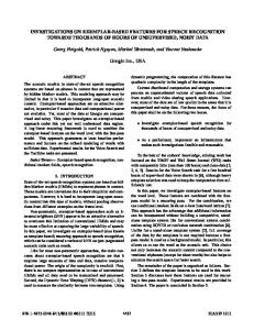
Figure 3: The Henneberg method in 3-space. V.A. stands for the vertex addition, E.S. stands for the edge split. Double-lined edges indicate the edges created for the new vertex. Dashed edges indicate the removed edges in the edge splitting.
Theorem 2. (Edge Split Theorem) Let G , {V, L} be a graph with a vertex i of degree d + 1, let Vi be the set of vertices incident to i, and let G∗ , {V ∗ , L∗ } be the subgraph obtained by deleting i and its d+1 incident edges. Then G is generically d-isostatic if and only if there is a pair j, k of vertices of Vi such that the S edge (j, k) is not in L∗ and the graph G0 = (V ∗ , L∗ (j, k)) is generically d-isostatic.
one might connect each pair of vertices in Vi . However this strategy would not give us a generically isostatic graph. In fact, for the removal of a vertex of degree k, we need to create k(k − 1)/2 new edges with this strategy. The number of new edges required for isostasy would be k − 2 and k − 3 in 2 and 3-space respectively. Maintaining generic isostasy in case of vertex removals in generically isostatic frameworks was considered in rigidity literature in [6]. One of the aims of this paper is to draw attention to their results for applications in vehicle formations.
This method starts from Gd in d-space at the first step (Gd is a single edge in 2-space and a triangle in 3-space) and then it either adds a new vertex with d edges to the existing graph, or it removes an existing edge by adding a new vertex connecting it to the end points of the removed edge and to other d − 1 vertices in the existing graph. The resulting graphs that we have after each step are generically isostatic. A sample graph in 3-space created by this method is depicted in Figure 3.
3.1 Formations in 2-space Removing a Vehicle with Two and Three Links: A generically isostatic graph G is shown in Figure 4a. The vertex 8 is removed with the two edges (8, 5) and (8, 7) in G (Figure 4b). For maintaining rigidity, no change is made with the remaining vertices and edges. The vertex 1 is removed with the three edges (1, 2), (1, 3) and (1, 5) in G. Then one of the edges, which is non-implicit, (2, 3), (2, 5) or (3, 5) is created as shown in Figure 5a. The existence of a non-implicit link was proved in [6]. The resulting graph is generically isostatic. The proofs are based on the vertex addition and edge split theorems. The existence of a non-implicit link in the subsequent analogous proofs is based on the proofs in [6].
3 The Closing Ranks Problem One way to solve the closing ranks problem would be determining links for the remaining vehicles from the very beginning. However generating a whole new formation with the remaining vehicles is not practical if a minimal rearrangement of links between vehicles suffices to keep the formation rigid. By the minimal rearrangement, we mean the following in graph theoretic terms. Assume that a generically isostatic graph G with a vertex i is given. Let {1, 2, . . . , n} denote the set of vertices in G. Given that the vertex i is removed from the graph, we want to maintain rigidity with the set of vertices {1, 2, . . . , n} \ {i}. Minimal rearrangement is preserving all the edges except the incident edges to i and creating new edges such that the new graph G∗ is isostatic. To maintain rigidity,
Removing a Vehicle with Four and Higher Number of Links: Lemma 3. Let G = (V, E) be a generically isostatic graph with a vertex i of degree four, which has a set of neighboring vertices, Vi . Let G∗ denote the resulting 3
(a)
(b)
(a)
(b)
Figure 4: (a)The initial graph representing a point forma-
Figure 5: (a) The vertex 1 of degree three is removed and
tion. (b) The vertex 8 of degree two is removed.
the edge (2,5) is created to maintain rigidity. (b) The vertex 4 of degree four is removed and the edges (2,6),(5,7) are created to maintain rigidity.
non-rigid graph after the vertex is removed. Then for some choice of two non-implicit edges among the vertices in Vi , the graph G∗∗ formed from G∗ by creating these edges is generically isostatic.
3.2 Formations in 3-space Removing a Vehicle with Three and Four Links: Given a generically isostatic graph G as shown in Figure 6a, consider the case when the vertex 3 with the three edges (3, 1), (3, 2) and (3, 5) is removed as shown in Figure 6b. For maintaining rigidity, no changes with the remaining vertices and edges need to be done. Consider the case when the vertex 8 with the four edges (8, 2), (8, 5), (8, 7) and (8, 11) is removed in G (Figure 7a). Rigidity is maintained as follows. One of the edges, which is non-implicit in the set {(2, 5),(2, 7),(2, 11),(5, 7),(5, 11),(7, 11)} (Figure 7b) is created. The proofs are analogous to 2-space cases.
Proof: We choose an isostatic graph G with the vertex i and the vertices in Vi . We remove one of the edges of i, and call it G0 . To maintain isostasy we create an edge between two points in Vi which is not implicitly present. If we add this edge, we create G00 which is isostatic and has a vertex i with degree three. We can replace i with a non-implicit edge between two vertices in Vi . Hence a vertex with degree 4 can be replaced by two edges between the vertices in Vi . Figure 5b shows an example where the vertex 4 of degree four is removed and the edges are created to maintain rigidity. Now, we remove a vertex with five or higher number of edges in a rigid graph. We maintain rigidity using the following theorem.
Removing a Vehicle with Five and Higher Number of Links: The vertex 7 with five edges is removed as shown in Figure 8a. To maintain rigidity with the remaining vertices, the following theorem is used.
Theorem 4. (replacing a vertex of degree k, k ≥ 5) Let G = (V, E) be a generically isostatic graph with a vertex i of degree k and with a set of neighboring vertices Vi . Then, for some choice of k −2 non-implicit edges among the vertices in Vi , the graph formed by removing i and the edges whose one end point is i, and adding these k − 2 edges is generically isostatic.
Lemma 5. Let G = (V, E) be a generically isostatic graph with a vertex i of degree five and with a set of neighboring vertices Vi . Then, one of the following is true: (i) for some choice of two non-incident edges among the vertices in Vi , the graph G1 formed from G by creating these edges is generically isostatic; or (ii) for two choices of incident pairs of edges among the vertices in Vi , (not all incident with a single vertex), the two graphs G2 and G3 formed from G by creating these pairs of edges are both generically isostatic.
Proof: The case for k = 4 has been shown in Lemma 3. Now we are going to show for k ≥ 5. Assume that the theorem holds for k = n − 1. For k = n, we choose an isostatic graph G with vertex i and the set of neighboring vertices Vi . We remove one of the edges of i, and call it G0 . To maintain isostasy we create an edge between two vertices in Vi which is not implicitly present. If we add this edge, we create G00 which is isostatic and has a vertex i with degree n − 1. From our assumption, we can remove the vertex i by creating n−3 new edges. Hence, we can maintain isostasy by creating a total of n − 2 edges in case of removing a vertex with degree n.
In Figure 8b, the edges (5,10),(6,8) are created to maintain rigidity. Now, a vehicle with six or higher number of links is removed in a rigid formation. The following theorem is used to maintain rigidity, which has an analogous proof of Theorem 4. Theorem 6. (replacing a vertex of degree k, k ≥ 6) Let G = (V, E) be a generically isostatic graph with a vertex i of degree k and with a set of neighboring vertices, Vi . Then, for some choice of k − 3 non-implicit edges among the vertices in Vi , the graph formed by removing i and the edges whose end point is i, and adding these 4
Figure 6: (a) A generically isostatic graph in 3-space. (b)
Figure 8: (a) The vertex 7 of degree five is removed. (b)
The vertex 3 of degree three is removed, and the resulting formation is still rigid.
The links (5,10), (6,8) are created to maintain rigidity.
other vertex. By circumcircle is meant the circle passing through the vertices of a triangle. Secondly the distance between any two vertices in the Delaunay triangulation is at most a constant times the Euclidean distance. Finally, empirical results suggest that in any dimension the edge skeleton of the Delaunay triangulation usually has small vertex degree and small total length [2]. There are often implicit edges in the Delaunay triangulation and this is undesirable for formations with minimum communications/sensing links. Here two methods of avoiding implicit edges are proposed while still using the nice property of large angles between the Delaunay edges. These methods can be extended to 3space. These two types of formations are called the minimal Delaunay triangulation and the minimal Delaunay edge formation. While the minimal Delaunay triangulation is composed of triangles, the minimal Delaunay edge formation is not necessarily. Let i and j be two vertices in V. An edge (i, j) is called a Delaunay edge if and only if there exists a circle passing through i and j that does not enclose any other vertex in V. An isostatic point formation with the Delaunay edges is called the minimal Delaunay edge formation. Note that the minimal Delaunay triangulations and the minimal Delaunay edge formations are created by the Henneberg method by using the Delaunay triangle and the Delaunay edge properties. In the sequel we give a way of creating these two types of formations.
Figure 7: (a) The vertex 8 of degree four is removed. (b) The link (7,11) is created to maintain rigidity.
k − 3 edges is generically isostatic.
4 The Delaunay Formations Here, some geometric flavor is added to the formations created by the Henneberg method. While adding new vertices by the vertex addition or the edge split, the new edges will be picked in such a way that the minimum angle between two incident edges in a formation is as large as possible. The large angle property plays a role in avoiding obstructions between vehicles. By the Delaunay formations, three types of formations are meant, namely the Delaunay triangulation, the minimal Delaunay triangulation and the minimal Delaunay edge formation (see Figure 9). The Delaunay triangulation, well known in computer graphics and in computational geometry literature, was proposed in [3] for creating rigid point formations. A triangulation in the plane is a partition of a point set into triangles that meet only at shared edges. The Delaunay triangulation, although rigid but not necessarily isostatic, has a number of properties that makes it attractive [1], [2]. It maximizes the minimum angle of all triangulations of a given vertex set. It is composed of the Delaunay triangles. A triangle is Delaunay if and only if the circumcircle of the triangle does not enclose any
Creating the Minimal Delaunay Triangulations: We add two edges for each vertex addition to the end points of an existing edge in the point formation such that the resulting triangle has the smallest circumcircle. To meet our goals in measure of angles, we apply edge flipping in the resulting point formation. Creating the Minimal Delaunay Edge Formations: We add two non-implicit edges with minimum lengths for each vertex addition. To meet our goals in measure of angles, we apply edge flipping in the result5
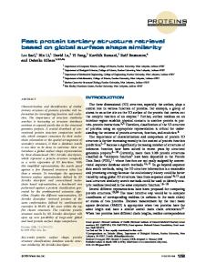
Figure 10: (a) A minimal Delaunay edge formation showing the vertex and edges (with dotted lines) to be removed, (b) New edges (depicted by double lines) are created to maintain rigidity where each edge is a Delaunay edge.
Figure 9: (a) The Delaunay triangulation of a given vertex set. (b) The minimal Delaunay triangulation of the same vertex set. (c) The minimal Delaunay edge formation of the same vertex set.
6 Conclusions ing point formation.
A systematic way of maintaining rigidity in case of vehicle removals in formations for coordinating mobile autonomous vehicles with the minimum communication/sensing links is presented. The method creates the minimum number of new links while preserving the ones that have not been removed. Hence, creating a new formation from the very beginning is not needed. The method can be applied to removed vehicles with any number of links in both 2 and 3-space. The minimal Delaunay edge formations, which are formations created by the Henneberg method with some geometric properties, are also introduced. Splitting-merging and reconfiguration of rigid formations will be presented in a separate paper.
5 Closing Ranks in the Delaunay Formations The Delaunay Triangulations: We state the following theorem for maintaining rigidity and the Delaunay property in case of vertex removals in a formation created by the Delaunay triangulation. Theorem 7. Let Fp = (V, L) be a generically rigid point formation created by the Delaunay triangulation. When a point pi is removed from Fp , the polygonal region consisting of all the triangles that are incident to pi is retriangulated satisfying the Delaunay property. Let F∗p denote the resulting point formation. Then F∗p is a generically rigid point formation.
References [1] Dobkin D.P., S. J. Friedman, and K. J. Supowit, ”Delaunay graphs are almost as good as complete graphs”, Proc. of the 28th Annual IEEE Symposium on Foundations of Computer Science, 1987, pp. 20-26.
The Minimal Delaunay Triangulations: For closing ranks, we use Theorem 7 as in the case of the Delaunay triangulations with the condition of one triangle per vertex as explained in creating the minimal Delaunay triangulations.
[2] Eppstein D., M. Bern, and F. Yao, ”The expected extremes in a delaunay triangulation”, Int. Journal of Computational Geometry and Applications, vol. 1 (1991), pp. 79-92.
The Minimal Delaunay Edge Formations: For closing ranks, we need to create a set of k − 2 and k − 3 nonimplicit links for a vertex of degree k in 2 and 3-space respectively as in the case of isostatic graphs, where each edge satisfies the Delaunay property. An example is shown in Figure 10. A minimal Delaunay edge formation showing the vertex and its edges (dotted lines) to be removed is depicted in Figure 10a. The new edges (double lines) are created to maintain rigidity where each edge is a Delaunay edge (Figure 10b).
[3] Eren T., P.N. Belhumeur, B.D.O. Anderson, and A.S. Morse, ”A framework for maintaining formations based on rigidity”, Proc. of the IFAC World Congress, Barcelona, Spain, 2002. [4] Laman G., On graphs and rigidity of plane skeletal structures. Journal of Engineering Mathematics, vol. 4 (1970), pp.331-340. [5] Roth B., Rigid and flexible frameworks. American Mathematical Monthly, vol. 88 (1981), pp.6-21.
Remark 8. Proposed methods can be extended to 3space.
[6] Tay T., and W. Whiteley, ”Generating isostatic frameworks”, Structural Topology, vol. 11 (1985), pp.21-69. 6