Chemical Oxidative Grafting of Conducting Poly(N-methyl aniline) onto Poly(ethylene terepthalate) P. Santhosh,1 T. Mathanmohan,1 M. Sankarasubramanian,1 S. Sankar,1 T. Vasudevan,1 A. Gopalan,1 and Kwang-Pill Lee2 1
Department of Industrial Chemistry, Alagappa University, Karaikudi, India Department of Chemistry Education, Kyungpook National University, Daegu, Korea
2
Received 3 March 2004; accepted 29 July 2004 DOI 10.1002/app.21319 Published online in Wiley InterScience (www.interscience.wiley.com). ABSTRACT: Detailed studies on the peroxidisulfate (PDS) initiated graft copolymerization of N-methyl aniline (NMA) with poly(ethylene terepthalate) (PET) were carried out in p-tolene sulfonic acid medium under nitrogen atmosphere. Experiments were designed to follow the rate of formation Rh of the poly(N-methyl aniline (PNMA), simultaneously with the rate of grafting of PNMA onto PET. Effects of concentration of NMA, PDS, PET, time, and temperature on Rh and graft parameters were followed. Kinetic equations were deduced to correlate the changes in the rate with
experimental conditions. Graft copolymers were isolated and grafting of PNMA onto PET was confirmed through FTIR, thermogravimetric analysis, and conductivity measurements. Tensile measurements showed that grafting of PNMA did not alter the tensile properties of PET. © 2004
INTRODUCTION
(methyl methacrylate) were grafted onto PET fiber by Gopalan and coworkers.3,4 Conducting polymers can be grafted onto various fibers and such studies have been the focus of much attention because they can provide wide applications in electrical and electronic devices.22–24 Moreover, conducting polymers have been grafted with conventional polymers, which are used in the fields of EMI shielding, gas sensors,25 and batteries.26 Chemical27 and electrochemical28 methods were used for the preparation of poly(aniline) (PANI) and its various ring-substituted derivatives. Processability of PANI has been improved by blending with other conventional polymers and also by grafting onto insulating materials.29 Grafting of PANI onto polyamino styrene was reported by Li et al.30 Yang and coworkers31 grafted PANI onto chitosan backbone and provided evidences through thermal, spectroscopic, and conductivity measurements. Li et al.32 could produce soluble PANI through grafting and the grafting was proved by morphology, spectroscopy, and electrical conductivity measurements. Abraham et al. 33 prepared a highly conducting blend of nylon 6/PANI film. Transparent PANI/ nylon 6 composite film was prepared and the degradation kinetics of electrical conductivity was reported.34 None of the above research articles details the kinetics of homopolymer formation. Our research team reported35– 42 few of the kinetic studies using peroxosalts as initiator for the graft copolymerization of aniline and o-toluidine onto PET, ny-
1,2
Grafting of vinyl polymers onto natural or synthetic3,4 fibers can be made through free-radical graft copolymerization. Grafting can be affected by highenergy radiation,5 low-energy radiation in the presence or absence of stabilizers,6 and chemical methods.7–9 In general, grafting results from abstraction of the hydrogen atom from a hydroxyl group1 or amino group10 attached to the active carbon atom11 in the polymer backbone. Initiation of grafting often occurs though a free-radical route and thus several free-radical–producing systems were tried for this purpose. The use of peroxosalts [potassium peroxodisulfate (PDS), potassium peroxomonosulfate (PMS), etc.] as initiator for free-radical initiation of vinyl polymerization and graft copolymerization has been exhaustively studied.12–18 For meeting specified applications, the properties of the textile fibers can be suitably modified by appropriate graft copolymerization. Kawahara and coworkers19 reported the grafting of methacrylamide onto silk fiber to modify the mechanical properties and structure of the fiber. Mechanical and thermal properties of poly(ethylene terepthlate) (PET) fiber could be altered by graft copolymerization of various vinyl polymers onto PET fiber.20,21 Poly(acrylonitrile) and polyCorrespondence to: A. Gopalan (
[email protected]). Journal of Applied Polymer Science, Vol. 95, 596 – 605 (2005) © 2004 Wiley Periodicals, Inc.
Wiley Periodicals, Inc. J Appl Polym Sci 95: 596 – 605, 2005
Key words: conjugated polymers; graft copolymers; kinetics (polym.); polyesters; thermogravimetric analysis (TGA)
GRAFTING OF CONDUCTING PNMA ONTO PET
lon 6, nylon 66, wool, polypropylene, and rayon fibers. Toppare and coworkers43 prepared a polypyrrole– polyamide composite by an electrochemical method and they provided spectroscopic evidence for the bonding between two polymers that resulted in grafting. Gregory and Tzou44 grafted PANI onto PET fiber and they reported the kinetic results. Bhadani et al.45 prepared a conducting fiber from natural fibers by an electrochemical method. The present investigation reports the kinetics of graft copolymerization of poly(N-methyl aniline) (PNMA) onto PET in p-toluene sulfonic acid (p-TSA) medium. Detailed investigation on the kinetics of graft copolymerization and the simultaneous homopolymerization was made. Rate equations correlating the experimental parameters were deduced. Evidence for the grafting of PNMA onto PET was provided through UV–visible spectroscopy, thermogravimetry, and conductivity studies. EXPERIMENTAL
597
mopolymer, PNMA, was Soxhlet extracted with acetone for 24 h to separate PNMA from the grafted PET. After the separation of PNMA, the grafted PET was dried at room temperature and weighed to a constant weight (W3 g). The difference between W3 and W1 gives the weight of NMA grafted onto PET. The difference between W2 and W3 gives the weight of the formed homopolymer, PNMA. The above experimental approach thus provides a way to follow the kinetics of both graft copolymerization and simultaneous homopolymerization. Rate measurements The rate of grafting (Rg), rate of homopolymerization (Rh), % grafting, and % grafting efficiency were calculated as follows: % Grafting ⫽
% Grafting efficiency ⫽
Materials N-Methyl aniline (NMA, Merck, Darmstadt, Germany), potassium peroxodisulfate (PDS, Merck), and p-toluene sulfonic acid (Merck) were used as received. PET was used after Soxhlet extraction with acetone to remove any adhering impurities and was dried at room temperature. Grafting copolymerization PET (W1 g), a required amount of NMA, and water were charged to a polymer tube and thermostated at 40°C for 30 min. The solution was deaerated by passing pure nitrogen gas for 30 min. Polymerization was initiated by the addition of a calculated volume of preaerated PDS (using standard solution). The time of adding the oxidizing agent PDS was taken as the starting time for the reaction (polymerization conditions were selected in such a way that no polymerization occurred in the absence of the added oxidant). This was ascertained by a separate experiment. At the end of the reaction time, the reaction was arrested by immersing the reaction vessel in ice-cold water and blowing air into the reaction vessel. Graft copolymerization experiments were carried out at 40°C for 90 min. The grafted PET and the homopolymer (PNMA) were filtered from the reaction mixture using a G4 sintered crucible, washed thoroughly with distilled water several times, dried at 70°C (for 4 h), and weighed to a constant weight, giving the total weight of the grafted polymer with the homopolymer (W2 g). The mixture of the grafted PET along with the ho-
W3 ⫺ W1 ⫻ 100 W1 W3 ⫺ W1 ⫻ 100 W4
where W4 is the weight of monomer used. Rg ⫽
W3 ⫺ W1 ⫻ 1000 VtM
Rh ⫽
W2 ⫺ W3 ⫻ 1000 VtM
where V is the total volume of the reaction mixture, t is the reaction time in seconds, and M is molecular weight of the monomer. UV–visible spectrophotometry analysis for the isolation of the grafted PET from PNMA The visible spectrum was recorded using a UV-2401 PC UV–visible spectrometer (Shimadzu, Kyoto, Japan) for the analysis of the PNMA content at various Soxhlet-extraction time intervals during the isolation of grafted PET from the homopolymer. Grafted PET with PNMA (green in color) in the doped state was treated with aqueous ammonia and the blue colored mass was separated by filtration, dried at 60°C for 5 h, and again treated with N-methyl pyrrolidone (NMP) with constant stirring. For each time interval, the Soxhlet extraction was subjected to UV–visible spectra analysis. FTIR spectrophotometry analysis PNMA and PNMA-grafted-PET were pressed as a disk with KBr and FTIR spectra were recorded using an
598
SANTHOSH ET AL.
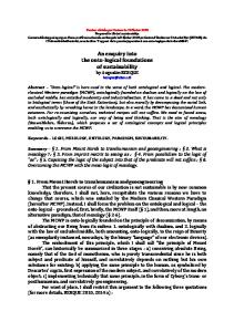
Figure 1
Visible spectra of PNMA in NMP at different Soxhlet-extraction times.
FTIR Rx 1 (Perkin–Elmer, Buckinghamshire, UK) at a resolution of 4 cm⫺1, at a minimum of 32 scans, and were signal-averaged at room temperature. Scanning electron microscopy (SEM) SEM observation was carried out for PNMA-graftedPET with Au-coated vacuum ion sputter by a liquid hydrogen method (JEOL 840 A, Tokyo, Japan). A rotating system was attached to the instrument and used for accurate measurements for various magnifications. Tensile strength measurement Tensile strength of the grafted and ungrafted PET samples was measured by using a tensometer (Type W 10,241, Monsanto, Poole, UK). A specimen length of 20 cm and a width of 3.3 cm were used to measure the tensile strength of grafted and ungrafted PET fibers. Thermogravimetric analysis (TGA) TGA of PET, PNMA-grafted-PET, and PNMA were made with a DuPont 2050 thermogravimetry analyzer (TA Instruments, New Castle, DE), using platinum crucibles with about 2 mg of the samples, under dynamic air atmosphere (30 mL/min) at a heating rate of 10°C min⫺1.
Conductivity measurements Conductivities of both grafted and ungrafted PET and PNMA were determined by a Keithley 617 electrometer (Keithley Metrabyte, Taunton, MA). A 1-cm length of the fiber was taken and its two ends were fixed at the two poles of the instrument and the current was passed. The meter directly showed the conductivity value.
RESULTS AND DISCUSSION Isolation of PNMA-grafted-PET fiber from homopolymer The PNMA-grafted-PET (PNMA-g-PET) was removed from the homopolymer and dedoped with aqueous ammonia solution for 5 h and then Soxhlet-extracted in NMP. At each interval of time, the fiber was removed from NMP, and the NMP extract was tested for the PNMA content through UV–visible spectroscopy. Figure 1 shows the visible spectra of PNMA in NMP solution for different Soxhlet-extraction time intervals. The visible spectra have a broad band, around 550 nm, characteristic of neutralized PNMA. The absorbance at 550 nm decreased with increasing Soxhlet-extraction time and became nil after 12 h, clearly verifying that this process completely removes the physically adsorbed PNMA on the grafted fiber.
GRAFTING OF CONDUCTING PNMA ONTO PET
Figure 2
599
FTIR spectra of (a) PNMA and (b) PNMA-grafted-PET.
Evidences for grafting FTIR spectroscopy The FTIR spectra of PNMA and PNMA-grafted-PET are presented in Figure 2. The spectrum of PNMAgrafted-PET [Fig. 2(b)] shows peaks that are characteristic of PNMA besides the peaks corresponding to PET. This clearly confirms that PNMA is grafted as side chains in PET. The peaks at 1635 and 1353 cm⫺1 represent the stretching frequency of the CAN band. The broad band around 3375 cm⫺1 is attributed to the presence of –NH stretching of the aromatic amine. The COH out-of-plane bending vibration of the substituted benzene ring appears at 826 cm⫺1. The peaks at 1496 and 1602 cm⫺1 indicate the presence of the ring stretch of the benzenoid and quinoid form. The peak appearing at 1256 cm⫺1 is attributed to the COH stretching of the aromatic secondary amine. The peaks at 890 and 772 cm⫺1 are attributed to the aromatic out-of-plane COH bending stretch. These peaks are responsible for the presence of PNMA units in the fiber chain. The other peaks observed in the spectrum are attributed to the PET backbone polymer.
obvious from the SEM topography that the PNMA was grafted onto PET fiber. Tensile strength measurements The results of tensile strength measurement of PNMAgrafted-PET and ungrafted PET (Table I) indicate that grafting does not influence the tensile strength of the fiber. The stress–strain curve (Fig. 4) justifies this. Thermogravimetric analysis Figure 5 presents the TGA curves of the PET, PNMAgrafted-PET fiber, and PNMA. The thermogram of PNMA [Fig. 5(iii)] shows two stages of weight loss.
SEM topography A scanning electron micrograph of PNMA-grafted-PET is presented in Figure 3 at a magnification of ⫻500. SEM topography shows the nature of grafting and it is
Figure 3 SEM microphotograph of PNMA-grafted-PET.
600
SANTHOSH ET AL.
TABLE I Tearing Strength for Grafted and Ungrafted Samples
Polymer
Grafted with
Maximum load applied (kg)
Tearing strength from graph (cm)
True extension (cm)
Percent elongation (%)
Stress (%)
Strain (%)
100% PET 100% PET
— NMA
17 14
9.2 8.8
2.375 2.200
25 25
617.05 510.94
43.7 35.4
The weight loss at lower temperature (115°C) is attributed to the loss of the counteranion. The first weight loss is about 15%, which begins from 115°C and continues up to 370°C. The second stage weight loss, which starts from 465°C, corresponds to the decomposition of the polymer backbone. The existence of thermal degradation around 370°C, characteristic of PNMA in the grafted fiber, adds evidence for the grafting of PNMA onto PET. A variation in weight loss and temperature of decomposition could be noticed between simple PNMA and grafted PET. In PNMA-grafted-PET, decomposition starts around 370°C and this can be assigned to the removal of dopants and subsequent decomposition of the structural units in PNMA. It can be seen that the mass retained beyond 450°C was higher for the grafted fiber compared to that of simple PET. This shows that the presence of PNMA in the grafted PET makes the fiber more stable than PET beyond 450°C.
Kinetics of graft copolymerization and homopolymerization Experiments were performed under different conditions to follow the kinetics of graft copolymerization and homopolymerization.
Effect of time on Rh and graft parameters Rg, Rh, and graft parameters were determined at various time intervals while keeping other experimental conditions constant, as given in Table III. Rg and Rh increased initially up to 90 min and then decreased with an increase in time. To follow the kinetics of graft copolymerization, a reaction time of about 90 min was selected. This is based on the fact that homopolymer formation was higher than graft copolymer formation beyond 90 min. Steady increases in % grafting and % grafting efficiency were witnessed up to 90 min (Table III).
Conductivity measurements The NMA-grafted-PET showed an improved conductivity over that of the ungrafted one (Table II). It was found that the conductivity value increased with increasing percentage of grafting. This also confirms the grafting of PNMA onto PET fiber.
Effect of [NMA] on Rh and graft parameters Experimental results were obtained by changing [NMA] in the range of 0.12 to 0.27 mol L⫺1 by keeping other experimental conditions constant. Rg and Rh values increase with an increase in [NMA] [Fig. 6(a) and (b)]. It is noted that % grafting increases steadily with increasing concentration of NMA. % Grafting efficiency remains unaffected for a change in concentration of NMA (Table IV). To determine the order dependency of [NMA] on Rg and Rh, plots of Rg versus [NMA] [Fig. 6(a)] and Rh versus [NMA] [Fig. 6(b)] were drawn. These plots were found to be straight lines, indicating a first-order dependency of Rg and Rh on [NMA].
Effect of [PDS] on Rh and graft parameters
Figure 4 Stress–strain curve for PNMA-grafted-PET.
[PDS] was varied between 0.036 and 0.098 mol L⫺1, while other experimental conditions were kept constant. Rg and Rh showed an increasing trend with increasing [PDS]. % Grafting and % grafting efficiency were also found to increase with [PDS] (Table V.) The straight line plots of Rg versus [PDS] [Fig. 7(a)] and Rh versus [PMS] [Fig. 7(b)], passing through the
GRAFTING OF CONDUCTING PNMA ONTO PET
Figure 5
601
Thermogram of (i) PET fiber, (ii) PNMA-grafted-PET fiber, and (iii) PNMA.
origin, imply first-order dependency of both Rg and Rh on [PDS].
Plots of Rg versus (amount of PET) [Fig. 8(a)] and Rh versus (amount of PET) [Fig. 8(b)] indicated the firstorder dependency of Rg and Rh on the amount of PET.
Effect of (amount of PET) on Rh and graft parameters
Effect of temperature on Rh and graft parameters
Weight of PET was varied from 0.20 to 0.456 g, while keeping other experimental conditions constant. It was observed that both Rg and Rh values increased steadily with increasing weight of PET fiber (Table VI). It is interesting to note that both % grafting and % grafting efficiency were found to increase steadily.
TABLE II Conductivity Measurements Polymer
% of Grafting
PET PNMA PNMA-grafted-PET
— — 2.56 6.45 9.25
Conductivity (⍀⫺1 cm⫺1) 0.95 39.57 11.25 14.56 19.28
G K K K K
Rg and Rh values obtained for the experiments with different temperatures (from 35 to 60°C) are given in Table VII. Rg and Rh increase initially up to 45°C and TABLE III Effect of Time on Rh, Rg, Percent Grafting, and Percent Efficiencya Time (s)
Rh ⫻ 106 (mol L⫺1)
Rg ⫻ 107 (mol L⫺1)
Percent grafting
Percent efficiency
900 1800 3600 5400 7200 9000
0.65 0.95 1.55 2.28 2.00 1.87
1.56 3.98 5.64 7.20 6.23 5.23
0.65 0.98 1.12 1.26 1.13 1.00
0.45 0.56 0.78 1.12 1.01 0.85
a [PDS] ⫽ 0.036 mol L⫺1; [NMA] ⫽ 0.12 mol L⫺1; wt. of PET ⫽ 0.2000 g; [p-TSA] ⫽ 1.0 mol L⫺1; temperature ⫽ 313 K.
602
SANTHOSH ET AL.
TABLE V Effect of [PMS] on Rh, Rg, Percent Grafting, and Percent Efficiencya [PMS] (mol L⫺1)
Rh ⫻ 106 (mol L⫺1)
Rg ⫻ 107 (mol L⫺1)
Percent grafting
Percent efficiency
0.036 0.048 0.061 0.073 0.090 0.098
2.28 2.9 3.58 4.47 5.67 6.13
7.20 9.23 10.90 13.08 15.23 18.00
1.26 2.98 5.23 6.27 9.25 10.25
1.12 1.56 2.99 3.87 5.06 5.73
a [NMA] ⫽ 0.12 mol L⫺1; wt. of PET ⫽ 0.2000 g; temperature ⫽ 313 K; [p-TSA] ⫽ 1.0 mol L⫺1.
the present work. The observed dependencies of rate of graft copolymerization and homopolymerization on the experimental parameters were found to be different in many respects. Earlier, Gregory and coworkers44 studied the effect of added fiber on chemical polymerization of aniline in the presence of PET fiber and no correlation was attempted to relate the changes in the rate of homopolymerization with reaction parameters. Wei et al.45 proposed an autoacceleration effect in the electrochemical polymerization of aniline by electrode surface in an attempt to explain
Figure 6 Effect of [NMA] on (a) Rg and (b) Rh. [PDS] ⫽ 0.036 mol L⫺1, wt. of PET ⫽ 0.2000 g, temperature ⫽ 313 K, [p-TSA] ⫽ 1.0 mol L⫺1.
decrease thereafter (Table VII). % Grafting and % grafting efficiency also follow a similar trend. The decrease in Rh and graft parameters at higher temperatures may be attributable to the depletion of monomer concentration as a result of evaporation. Arrhenius plots, log Rg versus 1/T and log Rh versus 1/T (Fig. 9), were drawn. The plots showed an initial increasing trend with a subsequent decreasing trend. It is pertinent to note that simultaneous measurements of homopolymerization were also followed in
TABLE IV Effect of [NMA] on Rh, Rg, Percent Grafting, and Percent Efficiencya [NMA] (mol L⫺1)
Rh ⫻ 106 (mol L⫺1)
Rg ⫻ 107 (mol L⫺1)
Percent grafting
Percent efficiency
0.12 0.15 0.18 0.21 0.24 0.27
2.28 3.05 4.12 5.06 5.98 6.25
7.2 9.56 11.23 13.98 15.01 17.23
1.26 2.13 4.96 5.23 7.25 8.56
1.12 1.09 1.15 1.17 1.20 1.15
[PDS] ⫽ 0.036 mol L⫺1; wt. of PET ⫽ 0.2000 g; temperature ⫽ 313 K; [p-TSA] ⫽ 1.0 mol L⫺1. a
Figure 7 Effect of [PDS] on (a) Rg and (b) Rh. [NMA] ⫽ 0.12 mol L⫺1, wt. of PET ⫽ 0.2000 g, temperature ⫽ 313 K, [p-TSA] ⫽ 1.0 mol L⫺1.
GRAFTING OF CONDUCTING PNMA ONTO PET
603
TABLE VI Effect of Weight of Fiber on Rh, Rg, Percent Grafting, and Percent Efficiencya Wt. of fiber (g) 0.200 0.252 0.290 0.352 0.403 0.456
Rh ⫻ 106 (mol L⫺1)
Rg ⫻ 107 (mol L⫺1)
Percent grafting
Percent efficiency
2.28 3.00 3.90 4.52 5.26 7.01
7.20 11.25 14.23 17.80 21.37 25.23
1.26 2.56 4.28 6.45 7.21 9.25
1.12 1.28 1.98 2.56 3.12 4.32
a [NMA] ⫽ 0.12 mol L⫺1; [PDS] ⫽ 0.036 mol L⫺1; temperature ⫽ 313 K; [p-TSA] ⫽ 1.0 mol L⫺1.
the changes in the induction time during the polymerization. A kinetic equation was proposed as R p ⫽ k[M] ⫹ k⬘[M][P]
(1)
where k is the rate constant of formation of PANI on a bare Pt electrode and k⬘ is the rate constant on PANIcoated Pt surface. Shim and Park46 proposed a kinetic
Figure 8 Effect of weight of fiber on (a) Rg and (b) Rh. [NMA] ⫽ 0.12 mol L⫺1, [PDS] ⫽ 0.036 mol L⫺1, temperature ⫽ 313 K, [p-TSA] ⫽ 1.0 mol L⫺1.
TABLE VII Effect of Temperature on Rh, Rg, Percent Grafting, and Percent Efficiencya Temperature (K) 308 313 318 323 328 333
Rh ⫻ 106 (mol L⫺1)
Rg ⫻ 107 (mol L⫺1)
Percent grafting
Percent efficiency
1.57 2.28 3.70 3.26 2.50 1.88
3.00 7.20 9.01 10.20 8.56 7.26
1.03 1.26 2.95 4.00 3.28 2.97
0.95 1.12 2.18 1.89 1.52 1.21
a [NMA] ⫽ 0.12 mol L⫺1; [PDS] ⫽ 0.036 mol L⫺1; wt. of PET ⫽ 0.2000 g; [p-TSA] ⫽ 1.0 mol L⫺1.
equation for the polymerization of aniline on a bare Pt electrode including the autoacceleration effect and proposed a type of the following equation as R p (ANI) ⫽ k1[ANI][PDS] ⫹ k2[ANI][TAS]
(2)
where k1 and k2 are the rate constants of formation of PANI on a bare Pt electrode surface and the rate constant of PANI-coated Pt electrode surface, respectively. TAS is the total available surface. In the study by Shim and Park,46 the influence of the amount of added fiber on the rate of formation of homopolymer or rate of grafting was not considered. In the present study, a kinetic model including the additional effects resulting from the added oxidizing agent as well as the heterogeneous phase is envisioned. The rate of PNMA formation was specifically monitored for different [NMA], [PDS], and the amount of PET fiber, while graft copolymerization simultaneously occurred. To highlight the role of the amount of fiber on the autoacceleration effect (resulting from the presence of active sites in the backbone structure), the rate changes were correlated with the amount of fiber.
Figure 9 Effect of temperature on Rg and Rh. [NMA] ⫽ 0.12 mol L⫺1, [PDS] ⫽ 0.036 mol L⫺1, wt. of fiber ⫽ 0.2000 g, [p-TSA] ⫽ 1.0 mol L⫺1.
604
SANTHOSH ET AL.
TABLE VIII Rate Constants Values Rate constant
Value
k1h k3h k1g k3g
23.20 ⫻ 104 s⫺1 g⫺1 1.52 ⫻ 106 mol L⫺1 s⫺1 65.95 ⫻ 104 s⫺1 g⫺1 1.95 ⫻ 106 mol L⫺1 s⫺1
here based on our experimental results and earlier literature35– 42 on grafting of PANI onto textile fibers. We envisage direct interaction of the monomer (NMA) and initiator (PDS) as the initiation step in these polymerization reactions. Primary reactions NMA ⫹ PDS 3 NMA ⫹•⫹products
On knowing the dependencies of various experimental parameters on Rp (NMA) and information that plots of Rp (NMA) versus [NMA] [Fig. 6(b)] and Rp (NMA) versus [PDS] [Fig. 7(b)] are straight lines, and Rp (NMA) versus wt. of fiber [Fig. 8(b)] is a straight line with definite intercepts, a modified representation of eq. (2) is proposed here: R h (NMA) ⫽ k1h[NMA][PDS] (wt. of fiber) ⫹ k2h[NMA][TAS] ⫹ k3h
PDS 3 2SO 4⫺•(R •) R • ⫹ Fiber 3 Fiber • ⫹ Products R • ⫹ NMA 3 NMA ⫹• ⫹ Products Homopolymerization NMA ⫹• ⫹ NMA ⫹• 3 Dimer ⫹ 2H ⫹
(3)
where k1h is the rate constant corresponding to homopolymer formation; and k2h and k3h are the rate constants for the homopolymer formation, taking into account the additional effects of available surface and probable change attributed to grafting. TAS includes the surface of homopolymer and grafted on a weight basis. The value of k3h can be obtained from the intercept of the plot of Rp (NMA) versus [NMA] [Fig. 6(b)]. Because the rate of grafting also has a similar trend, an equation similar to eq. (3) is proposed to explain the grafting:
Dimer ⫹ R • 3 Dimer ⫹• ⫹ Products Dimer ⫹ PDS 3 Dimer ⫹• ⫹ Products Dimer ⫹• ⫹ Dimer ⫹• 3 Oligomer ⫹ 2H ⫹ Oligomer ⫹ PDS 3 Oligomer ⫹• ⫹ Products Oligomer ⫹ R • 3 Oligomer ⫹• ⫹ Products Oligomer ⫹• ⫹ Oligomer ⫹• 3 PNMA ⫹ 2H ⫹ PNMA ⫹ PDS 3 PNMA ⫹• ⫹ Products ⫹ R • (auto acceleration)
R g (NMA) ⫽ k1g[NMA][PDS] (wt. of fiber) ⫹ k2g[NMA][TAS] ⫹ k3g
(4)
where k1g is the rate constant corresponding to graft copolymer formation; and k2g and k3g are the rate constants for the graft copolymer formation, taking into account the additional effects of available surface and probable change attributed to grafting. The values of the rate constants appearing in eqs. (3) and (4) were determined and are presented in Table VIII. It is important to note that the rate constant for homopolymer formation was comparatively higher (23.20 ⫻ 10⫺4 s⫺1 g⫺1) than that reported for aniline polymerization (0.0008 min⫺1).44 Further, the rate constant for grafting (65.95 ⫻ 10⫺4 s⫺1 g⫺1) was higher than that for homopolymerization, signifying the dominance of grafting over homopolymerization. Mechanism A probable mechanism explaining the simultaneous homopolymerization, along with grafting and autoacceleration effect by the presence of fiber, is presented
PNMA ⫹• ⫹ NMA 3 NMA ⫹• ⫹ PNMA Graft copolymerization NMA ⫹ Fiber • 3 Fiber–NMA ⫹• Fiber–NMA ⫹• ⫹ NMA 3 Fiber–dimer ⫹ 2H ⫹ Fiber–dimer ⫹ R • 3 Fiber–dimer ⫹ • Fiber–dimer ⫹ PDS 3 Fiber–dimer ⫹• ⫹ Products Fiber–dimer ⫹• ⫹ NMA 3 Fiber–oligomer ⫹ 2H ⫹ Fiber–oligomer ⫹ R • 3 Fiber–oligomer ⫹• ⫹ Products Fiber–oligomer ⫹• ⫹ oligomer ⫹• 3 Graftcopolymer ⫹ 2H ⫹ Fiber ⫹ R • 3 Fiber • ⫹ Products
GRAFTING OF CONDUCTING PNMA ONTO PET
Fiber • ⫹ NMA 3 NMA ⫹ • ⫹ Products (acceleration for homopolymerization) NMA ⫹• ⫹ NMA 3 Dimer ⫹ 2H ⫹ References 1. Okeieimen, E. F.; Idehen, K. L.; Ahiedu, H. J Appl Polym Sci 1987, 34, 737. 2. Padma Nayak, L.; Lenka, S.; Mishra, M. K. J Appl Polym Sci 1981, 36, 733. 3. Gopalan, A.; Vasudevan, T.; Manisankar, P.; Paruthimal Kalaignan, G.; Ramasubramanian, A.; Hariharan, S. S. J Appl Polym Sci 1995, 56, 1299. 4. Gopalan, A.; Vasudevan, T.; Manisankar, P.; Paruthimal Kalaignan, G.; Ramasubramanian, A.; Hariharan, S. S. J Appl Polym Sci 1995, 56, 1715. 5. Arai, K.; Negishi, M.; Komiso, S.; Jakada, K. Appl Polym Symp 1971, 18, 545. 6. Needles, H. L.; Wasley, W. I. Text Res J 1959, 39, 97. 7. Negashi, M.; Arai, K.; Okada, S. J Appl Polym Sci 1967, 11, 115. 8. Kantouch, A.; Hebeish, A.; Bendak, A. Eur Polym Mater 1971, 7, 153. 9. Nayak, P. L.; Mohanty, T. R.; Singh, B. C. Macromol Chem 1975, 176, 873. 10. Mukherjee, A. K.; Gupta, B. D. J Appl Polym Sci 1985, 30, 2253. 11. Giri, G.; Samal, R. K. J Appl Polym Sci 1991, 42, 2371. 12. Anbarasan, R.; Jeyasekan, J.; Sudha, M.; Gopalan, A. Macromol Chem Phys 2000, 201, 1869. 13. Anbarasan, R.; Jayaseharan, J.; Gopalan, A. J Appl Polym Sci 2002, 85, 2317. 14. Vivekanatham, T. S.; Gopalan, A.; Vasudevan, T.; Umapathy, S. J Appl Polym Sci 2000, 56, 524. 15. Vivekanatham, T. S.; Gopalan, A.; Vasudevan, T. Umapathy, S. Polymer 1999, 40, 807. 16. Vivekanatham, T. S.; Gopalan, A.; Vasudevan, T.; Umapathy, S. J Polym Sci Part A: Polym Chem 1998, 36, 2715. 17. Seetharaman, S.; Hariharan, S. S.; Gopalan, A.; Subbaratnam, N. R. Polym Commun 1989, 30, 136. 18. Gopalan, A.; Paulrajan, S.; Subbaratnam, N. R.; Venkatarao, K. J Polym Sci Polym Chem Ed 1985, 23, 1861.
605
19. Kawahara, Y.; Shioya, M.; Kikutani, K.; Takaku, A. J Text Inst 1975, 88, 5. 20. Sacak, M.; Oflaz, M. J Appl Polym Sci 1993, 50, 1909. 21. Sacak, M.; Senkaya, F.; Talu, M. J Appl Polym Sci 1992, 49, 1737. 22. Jenekha, A. A. Nature 1986, 332, 345. 23. Koezuka, H. Tsumusa, A. Synth Met 1989, 28, 753. 24. Mayer, W. H.; Kiess, H.; Binggelli, B.; Meier, E.; Harbeke, G. Synth Met 1991, 10, 255. 25. Kumar, N.; Vadera, S. R.; Sing, S.; Dass, G.; Negi, S. C.; Apaena, P.; Tuli, A. Def Sci J 1996, 46, 91. 26. Ratdiffe, N. M. Anal Chim Acta 1990, 239, 257. 27. Schocklette, L. W.; Jow, T. R.; Maxfiled, M.; Haxami, R. Synth Met 1989, 28, C655. 28. Im, S.; Byun, S. W. J Appl Polym Sci 1994, 51, 1221. 29. Anbarasan, R.; Vasudevan, T.; Paruthimal Kalaignan, G.; Gopalan, A. Int J Polym Anal Charac 1999, 5, 247. 30. Li, S.; Cao, Y.; Xue, Z. Synth Met 1987, 20, 141. 31. Yang, S.; Tirmizi, A.; Risen, W. M. Synth Met 1989, 32, 191. 32. Li, S.; Cao, Y.; Dong, H. Synth Met 1989, 29, E329. 33. Abraham, D.; Bharathi, A.; Subramanyam, S. V. Polymer 1996, 37, 5295. 34. Byun, S. W.; Im, S. S. Synth Met 1995, 69, 219. 35. Anbarasan, R.; Vasudevan, T.; Gopalan, A. Eur Polym J 2000, 36, 1725. 36. Anbarasan, R.; Vasudevan, T.; Gopalan, A. J Appl Polym Sci 1999, 73, 21. 37. Anbarasan, R.; Vasudevan, T.; Gopalan, A. Int J Polym Mater 1998, 42, 195. 38. Anbarasan, R.; Vasudevan, T.; Gopalan, A. J Mater Sci 2000, 35, 617. 39. Anbarasan, R.; Vasudevan, T.; Gopalan, A. J Polym Mater, to appear. 40. Anbarasan, R.; Muthumani, N.; Vasudevan, T.; Gopalan, A. J Appl Polym Sci 2001, 79, 1283. 41. Anbarasan, R.; Jayaseharan, J.; Sudha, M.; Gopalan, A. Int J Polym Mater 2000, 48, 199. 42. Anbarasan, R.; Jayasekaran, J.; Sudha, M.; Bhuvaneshwari, R.; Sivakumar, C.; Gopalan, A. Compos Interface 2000, 17, 317. 43. Toppare, L.; Yigit, S.; Hacaloglu, J. Polymer 1997, 38, 5119. 44. Tzou, K.; Gregory, R. V. Synth Met 1992, 47, 267. 45. Wei, Y.; Hariharan, R.; Patel, S. A. Macromolecules 1991, 23, 758. 46. Shim, Y. B.; Won, M. S., Park, S. M. J Electrochem Soc 1990, 137, 538.