Computer Network Simulation Using NS2
Page 1 of 33
CHAPTER 6 WIRED NETWORK SIMULATION
6.1 Introduction The architecture of NS2 and certain preliminary concepts were discussed in Chapter 4 and Chapter 5. In this chapter, we discuss simulation of a wired network. Computer communication networks may be classified into two types: wired and wireless. In wired networks, the nodes are connected via cables. On the other hand, in wireless networks the nodes are connected with air as the medium. In the first case a topology of the network is usually defined, whereas in the second case nodes can move and the topology changes dynamically and hence no static topology can be defined. If a node comes within the communication range of another node, then direct communication between the two nodes is possible. In this chapter we discuss simulation of wired networks, and wireless network simulation is discussed in Chapter 7. We start with a few simple examples and gradually develop programs of increasing sophistication with the objective of being able to simulate real-life wired network scenarios for various kinds of networks.
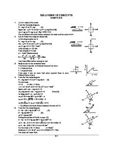
6.2 Step-by-Step Wired Network Simulation Complete network simulation using NS2 involves many steps. To be able to satisfactorily simulate a network, a thorough understanding of these steps is necessary. A minimal step-by-step process to simulate any wired network is provided in the form of a block diagram in Figure 6.1. The different blocks are briefly discussed below. Each block represents a step, and the details of these steps are discussed in subsequent sections. All simulation scripts are written using Tcl.
Figure 6.1 Block diagram for wired network simulation in NS2 Step I: Creating the Event Scheduler Creating the event scheduler is the first program statement in any NS2 program. This scheduler queues any event that is generated by the simulation. The scheduler is an object of the simulator class. The following Tcl statement is used to create the event scheduler. set ns [new Simulator] Step II: Tracing This step is essential if you need to record the events that are occurring during the simulation experiments in a specific format in a plain-text file. These files are treated as the output of any
file:///C:/Users/admin/AppData/Local/Temp/bityefte.y04/OPS/xhtml/13_Chapter06.xht... 4/16/2018
Computer Network Simulation Using NS2
Page 2 of 33
simulation program execution. Two types of traces are available. One is used by the programmer to analyze the simulation results for various network parameters (like throughput, delay, etc.) and is called the Packet Trace/Event Trace/NS trace. The other one is used by the network animator (NAM) module to create visualization for the simulation and is known as the NAM Trace. The following Tcl syntax may be used to generate traces. Syntax: Packet Trace set ptf [open
w] $ns trace-all $ptf Syntax: NAM Trace set ntf [open w] $ns namtrace-all $ntf The file names given in angular brackets are user defined, i.e., the user has to provide the file name. Packet-trace is discussed in more detail in Section 6.7. Step III Creating Network Topology In this step the network topology is created. Different kinds of network topologies can be defined as per the user requirement. To realize a required topology, a set of nodes is first created, and the links between the nodes are defined as per the requirement. The syntax to create the nodes and links is provided below. Also, some complete programs are given to demonstrate the creation of different topologies. These programs may be executed to visualize the topologies in the NAM window. Syntax: Creating nodes set [$ns node] Syntax: Creating a link between two nodes $ns [new Agent/UDP] Syntax: Attach the agent to a specific node (sender) $ns attach-agent Syntax: Create sink agent set [new Agent/Null] Syntax: Attach the sink agent to another node (receiver) $ns attach-agent Syntax: Connect two agents $ns connect Step VI: Application Now we need to attach an application that generates packets for transmission through the connections (traffic generation). Out of many traffic types available in NS2, we choose constant bit rate traffic for this example. Other traffic types will be discussed later in this chapter. Syntax: Create and attach application traffic set [new Application/Traffic/CBR] attach-agent Syntax: start and stop data transmission $ns at " start" $ns at " stop" Step VII Finishing Touch The time period for which the simulation should run needs to be mentioned. "finish" ‘finish’ is a user-defined procedure, designed to perform some routine tasks at the end of the simulation like closing trace files, executing NAM visualization, etc. Finally, run the simulation. Syntax: run the simulation $ns run This command should always be the ‘last line’ of each simulation. The complete program is given in Listing 6.4. Write and save the program in a file with extension .tcl and then execute the program from the command prompt (ns myFirstNSProgram.tcl). If everything goes fine (no syntax error), then it will execute the simulation for the defined duration of time and automatically open the NAM visualization. To observe the visualization of data transmission, the play button of the NAM window may be clicked. Listing 6.4 Complete program for two-node network simulation set ns [new Simulator] 1 set nf [open twoNode . nam w] 2 $ns namtrace - all $nf 3 4 set n0 [$ns node] 5 set n1 [$ns node] 6 7 $ns duplex - link $n0 $n1 100Mb 5ms DropTail 8 9 set udp [new Agent/UDP] 10 $ns attach - agent $n0 $udp 11 set null [new Agent/Null] 12 $ns attach - agent $n1 $null 13 $ns connect $udp $null 14 set cbr [new Application/Traffic/CBR] 15 $cbr attach - agent $udp 16 $ns at 1.0 “$cbr start ” 17 $ns at 3.0 “$cbr stop ” 18 $ns at 3.1 “finish ” 19 20 21 proc finish {} { global ns nf 22 $ns flush - trace 23 close $nf 24 exec nam twoNode . nam & 25 exit 0 26 27 } 28 29 $ns run When the program in Listing 6.4 is executed, it produces a visualization in NAM due to line 25 of the program. The animation will show packet flow from node 0 to node 1. The above command establishes a simplex (unidirectional) link between node n1 and node n2 with the specified bandwidth (BW) and propagation delay. The parameter defines the type of queue buffer to be used by the link, and, according to the queue type mentioned, different arguments may be passed through the parameter. This link can send data from n1 to n2; the reverse communication is not possible. However, to perform duplex communication between nodes, the following command may be used. $ns duplex-link This command establishes a bi-directional link between node n0 and node n1, with specified bandwidth and propagation delay. As usual, the parameter defines the type of queue to be used by the link. The following command is used to set different duplex-link attributes, such as physical orientation of the links, color, label, or queue position in NAM visualization. $ns duplex-link-op $ns link-lossmodel The above command introduces losses in to the link between node and node. $ns lossmodel Above command is used to insert a loss module in regular links. The queue limit may be specified as $ns queue-limit $n1 $n2 Queues are used to hold or drop the packets. Packet scheduling is done to decide whether a packet is to be inserted in the queue for further processing or dropped. Queueing discipline is nothing but the management of the queue buffer to regulate a queue in a particular way. Many queueing disciplines are supported; some of them are discussed below. or $ns newLan where nodeList: A set of LAN member nodes within double quotes separated with a space BW: LAN bandwidth in Mb or Kb #To join a source agent with a sink agent (not a connection establishment, but fixing a source and a corresponding destination) $ns_ connect UDP configuration parameters $udp set packetSize_ ;# default 1000 bytes $udp set dst_addr_ $udp set dst_port_ $udp set class_ $udp set ttl_ … etc. The default values for the above parameters may be found in ~ ns/tcl/lib/ns-default.tcl. Almost all programs illustrated so far use UDP at the transport layer, so no separate examples are provided here. But the reader should use UDP with the varying value of parameters given above and compare the results..tr. The packet trace information is very important, as it is useful to measure the performance of the network. To effectively extract the required information for various network performance parameter values from a packet trace file is the key challenge here. To do so, the format of the packet trace file must be understood. To generate a packet trace file for any simulation, use the following Tcl code in an NS simulation script, as discussed in Step II of Section 6.2. set ptf [open w] $ns trace-all $ptf When the simulation finishes, the trace file named pktTrace.tr is produced that stores all the events generated in the simulation. Each event is recorded in a separate row in the trace file. A few events are stored in a packet trace file as follows. Event 1 + 1.01 0 1 cbr 500 ----- 0 0.0 1.0 2 2 Event 2 - 1.01 0 1 cbr 500 ----- 0 0.0 1.0 2 2 Event 3 r 1.014 0 1 cbr 500 ----- 0 0.0 1.0 0 0 … Table 6.3: Event trace format Column# $ftp producemore rtmodel provides a failure model to be applied either to the nodes or to the links available in a simulation topology. That is, if the last argument contains two nodes, then it is understood as a link failure between these two nodes. Otherwise if only one node is given in the argument, it is considered to be a failure of that node. Model parameters are different for each model, and args specifies the nodes or links to which the failure model will be applied. The various failure models are as follows. i) Deterministic Model This is an on/off model that takes four parameters as follows. Starting from start-time (simulation starting time) the link remains active (up) for a duration of up-interval and inactive (down) for a period of down-interval. This up-down cycle continues until finish-time (end of simulation). The default values for model parameters are start-time: 0.5sec finish-time: end of simulation The values of up-interval and down-interval are considered as the mean of the exponential distribution which defines the time of the up/down cycle for the link/node. The default values for different parameters are as follows. start-time: 0.5s finish-time: end of simulation up-interval: 10s down-interval: 1s To assume a default value, a “-” symbol is used in place of an actual value (see example below). Example: 0.8 1.0 1.0 ;# start at 0.8s, up/down = 1.0s, finish is default 5.0 0.5 ;# start is default, up/down = 5.0s, 0.5s, finish is default − 0.7;# start, up interval are default, down = 0.7s, finish is default − − − 10 ;# start, up, down are default, finish at 10s Example: A node failure cycle $ns rtmodel Exponential 0.7 1.5 1.0 $n1 link- v 0.5 link-up 1 2 v 2.8 link-down 7 3