DEVELOPMENT OF A GROUND SOURCE HEAT PUMP SYSTEM WITH GROUND HEAT EXCHANGER UTILIZING THE CAST-IN-PLACE CONCRETE PILE FOUNDATIONS OF BUILDINGS
K. Sekine Technology Center, Taisei Corporation 344-1, Nase-cho, Totsuka-ku, Yokohama 245-0051, Japan Tel: 81-45-814-7239
[email protected] R. Ooka, S. Hwang, Y. Nam Institute of Industrial Science, University of Tokyo 4-6-1 Komaba, Meguro-ku, Tokyo, Japan Y. Shiba Development, Zeneral Heatpump Industry Co., Ltd, M. Eng. 121, Mishinden Ohdaka-cyo, Midori-ku, Nagoya 459-8001, Japan
1.
BACKGROUND
Ground-source heat pump (GSHP) systems can achieve a higher coefficient of performance than conventional airsource heat pump (ASHP) systems because the ground, which functions as the heat source or sink, is at a higher temperature in winter and lower in summer than the air temperature (Kavanaugh 1992; Kavanaugh et al 1997). In addition, there will likely be some mitigation against the effects of the heat island phenomena, as this system does not emit exhaust heat into the atmosphere during air conditioning. However, GSHP systems are not popular except as experimental versions in Japan. This is primarily due to the high cost of boring to run piping underground. For example, such boring costs average about ¥3,000/m (approx. US$30/m) in the USA, whereas the same work is about ¥10,000/m (US$100/m) in Japan. Thus, even if the heat pump performance in GSHP systems is more effective than that of the more common ASHP systems, the GSHP systems are unable to recoup the initial piping costs within their lifecycles. Recently, GSHP system employs the foundation piles of buildings as heat exchanger (so called “energy pile system”) is introduced into some buildings in order to reduce the initial boring cost (Hamada et al 1997; Arup Geotechnics 2002; Presetschnik et al 2005). However the effective and low cost design method for energy pile systems has not been developed yet. In addition, almost energy pile systems have used the precast prestressed concrete pile or the steel pipe pile. Recently, in Japan, the foundation piles of buildings in the urban area have used the cast-in-place concrete pile foundation for the reason of the traffic circumstances when carrying of piles or the cost reduction. The authors have developed a GSHP system (energy pile system) that employs the cast-in-place concrete pile foundation of buildings. In this research, a full-scale experiment was conducted. The heat exchange capability of this system, the subterranean temperature changes and performance of the heat pump were investigated. Furthermore, the construction costs of this system were also examined.
2.
SYSTEM OUTLINE
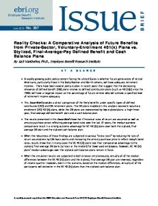
In this system, some U-tubes are arranged around the surface of cast-in-place concrete pile foundations as shown in Figure 1. The U-tubes are normally made of high-grade polyethylene or cross linked polyethylene. U-tube employed in this system is made of polyethylene. Polyethylene is very steady chemically, and is strong also in the temperature change. Thus, there is no worry to which polyethylene is deteriorated even if concrete curing (heating, swelling/shrinking) occurs. These U-tubes are usually 3/4 or 1 inch (27 or 34 mm) in diameter. The usual diameters of cast-in-place concrete pile foundations are from 1500 to 4000 mm. Thus, this arrangement is expected to offer superior heat exchange performance. The U-tubes are installed against the reinforcing bars used in the cast-in-place concrete pile foundations, so the strength of the foundation pile is ensured. Air conditioning
Cast-in-place concrete pile φ1500~4000mm
Geothermal Heat Pump
U-bend φ20~25mm Foundation piles
Figure 1:Outline of the heat exchange system using cast-in-place concrete piles
In the case of application of 1500mm cast in place concrete pile to the usual office building in Japan, one pile is usually set per 30 to 40m2 floor area each. In this study, heat extraction/rejection rate per one pile was about 180W/m. Therefore if pile length is 30m (it is very general in Japan), heat extraction/rejection rate per one pile became 5.4kW. This ability corresponds to the air conditioning load for 2 to 3 floor areas, i.e. about 1/3 of the total air conditioning load of a 8 stories office building which is very popular in Japan. Heat source for air conditioning in the office building is usually divided into several parts. In this case, geothermal heat from this pile system can be used as one parts of heat source. The other air conditioning load is supplemented with the usual air-source heat pump. These methods are quite reasonable and applicable. In this paper, a basic performance and the construction cost of this system are examined.
3.
FULL-SCALE EXPERIMENT
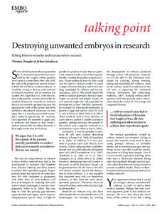
3.1 Experimental Equipment Outline An experimental institution was built on-site at the University of Tokyo in Chiba. Chiba is east of Tokyo, and the average annual air temperature is about 15.4°C, with the average air temperature in August being about 26.4°C and in January about 5.4°C. Accordingly, both heating and cooling functions are necessary. A plan of the experimental institution and the system configuration is shown in Figs. 2-3. The results of this experiment were obtained at a local site. Thus, people should apply these results at other sites carefully. A borehole log at this site is also shown in Fig.2 in order to show the locality of this experiment.
4537.5
3600
4537.5 depth [m] 1 2 3 4 5 6 7 8 9 10 11 12 13 14 15 16 17 18 19 20
Fun coil unit
Experiment room A
Geothrmal heat pump & Control panel
N 4000
×:Underground temperature measurement point
3675
Radiation panel
Preparation room
Experiment room A
Foundation pile B
Foundation pile A 45°
22.5° U-bends
1500
1250
3250
1500
1250
story [m]
log
soil
1.7
loam
3.2
clay loam
0.7 1.3 0.8
tuff clay silty clay clay fine
color
dark brown | pale red brown
groundwater level
12.67
fine sand
pale dark brown
soil map
6000
Figure 2:Plan of the Experimental Institution and Sail Map
FM
FM
M
Geothermal heat pump
T
M
Expansion tank 50 L
Experiment room B Radiation panel RC2000 P50 39line 1,940 L/h Cooling 3,000 kcal/h Heating 3,800 kcal/h
FM
Expansion tank 50 L
Radiation Panel
T
Wh
Watt-hour m eter
FM
Fun coil unit
Experiment room A Fun coil unit Cooling 3,000 kcal/h Heating 3,800 kcal/h
Wh Wh
Watt-hour m eter
Cold and Hot water pump flow:33L/min, head:12m, electric motor output:0.25kW Heat souce water pump flow:33L/min, head:25m, electric motor output:0.75kW
SH RH
SH RH
SH RH
20000 57.4
Watt-hour m eter
Geothermal heat pump Cooling:4.6kW (Cold water:12/ 7°C, Cooling water:30/35°C) Heating:5.7kW (Hot water:40/45°C, Heat souce water:14/ 9°C) Electric consumption:1.6kW (Cooling), 1.8kW (Heating) 200V Refrigerant : R407C
U-bends Polyethylene tube 25A, 20m
Cast-in-place concrete pile diameter:1500mm, (20m) U-bends 8 per pile
Figure 3:System configuration
There were two cast-in-place concrete piles (both 1,500 mm in diameter, 20 m tall) around which 8 U-tubes (External diameter: 34.0 mm; internal diameter: 28.8 mm) were installed. It is possible to control the number of Utubes in operation by opening and closing their valves. The system employed in this experimental equipment consists of a water-to-water heat pump with a reciprocating compressor (4.6 kW cooling, 5.7 kW heating). Cold and hot water circulates through a fan coil unit and a radiation panel in two examination rooms respectively, as shown in Figure 2. The flow of cold and hot water is 27 l/min (0.00045 m3/s). The flow of the heat source (sink) water is 33 l/min (0.00055 m3/s).
This system has two rooms. One has a fan coil unit installed. The other has a radiation air conditioner. Thermostat and electrical valves control the amount of water supplied to the fan coil unit. 3.2 Experiment Outline The heat pump in this system was operated from 9:00 to 18:00, Monday to Friday as in typical office buildings. It was not operated on Saturday or Sunday. In summer (from June to September), heat was discharged (sunk) into the ground. Conversely, in winter (from December to March), heat was extracted (sourced) from the ground. A list of the measurement items is shown in Table 1. Table 1:The Measurement Items Measured Item
Measuring equipment (permissible range)
Measurement point
Subterranean temperature
T-type thermo couples (±1°C)
Depth: 1m, 10m, 19m
U-bend surface temperature
T-type thermo couples (±1°C)
Depth: 1m, 10m, 19m
Heat source/sink water temperature
Platinum measurement resistor (±0.5°C)
In the pipe
Cold and hot water temperature
Platinum measurement resistor (±0.5°C)
In the pipe
Water flow
Flow meter (±2%)
In the pipe
Electrical power used
Electric power meter
Power panel
Outside temperature, relative humidity, wind velocity, wind direction, quantity of solar radiation, rainfall
4.
COOLING AND HEATING RESULTS IN 2003
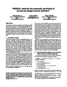
4.1 Underground Temperature Figure 4 shows the variations in the underground temperature at measuring points A and B and air temperature in 2003. The subterranean temperature was about 20°C one meter below ground level (G.L. –1m), about 19°C at G.L. –10m and about 17°C at G.L. –19m in both measuring points A and B as shown in Fig. 6 at the start of the airconditioning operation (7/16). The subterranean temperature at each point gradually rose thereafter. The subterranean temperature at G.L. –1m had reached about 25°C by the time the air-conditioning operation ended. The subterranean temperature at G.L. –1m was significantly influenced by the ambient air temperature. However, subterranean temperatures only changed a few degrees at G.L. –10m and G.L. –19m throughout the year. At the start of the heating operation (12/25), the subterranean temperature at G.L. –10m was about 19°C, while that at G.L. –19m was about 17°C. The subterranean temperatures at each point fell gradually after the start of this operation. The subterranean temperatures at G.L. –10m and G.L. –19m stabilized at about 15°C during the heating operation in February and remained nearly constant until the operation ended (3/28). 30
30 10
25
Measure Point A 45°
20
Heating
GL -1m GL -10m
5
5
2750
Foundation Pile A
GL -19m
Foundation Pile A
15
Temperature [ºC]
25 20 15
GL -1m GL -10m
GL -19m Air-Temperature
1250
0
0
Temperature [ºC]
45°
Heating
10
Cooling
Measure Point B
Cooling
6/28
8/17
10/6
11/25
1/14
3/4
4/23
6/28
8/17
10/6
11/25
1/14
3/4
4/23
Figure 4:Underground and air temperature variations (left: point A, right: point B)
30 25 15
20
:Temperature(13:00) :Heat Source Water Temperature
0
10
5
10
Temperature[ºC]
40 35 30 25 20
:Temperature(13:00) :Heat Sink Water Temperature
15
Temperature[ºC]
4.2 Heat Source/Sink Water Temperature The air temperature and heat source/sink water temperatures for cooling and heating are shown in Figure 5. The heat sink water temperature at the start of the cooling operation was about 20°C, rose gradually after that and reached about 29°C just before the end of the cooling period. The average temperature of the heat sink water and air during the cooling period were about 24.5°C and 29.2°C respectively. The heat sink water temperature was about 4.7℃ lower than the air temperature on average for the cooling period. And the maximum difference between the water temperature and the air temperature was 12.3℃ for the cooling period.
6/28
7/18
8/7
8/27
9/16
10/6
12/5
12/25
1/14
2/3
2/23
3/14
4/3
4/23
Figure 5: Heat sink/source water temperatures (left: cooling (sink), right: heating (source)) On the other hand, the heat source water temperature at the beginning of heating was about 17°C and fell gradually after the start of the operation and remained at about 13°C from early January until the end of March. The average air temperature during the heating period was about 9.9°C, while the minimum was about 1.1°C. the heat source water was about 3.1℃ higher than the air temperature on average for the heating period. The maximum difference between the water temperature and the air temperature was 11.9℃ for that period. Thus, using the ground water as a heat source or sink was more effective than using ambient air. Accordingly, GSHP is expected to be more effective than ASHP both in terms of cooling and heating.
4.3 Heat Extraction/Rejection From/Into The Ground The averages for the heat extraction and rejection either from or into the ground of the foundation piles A and B at the outset of the cooling and heating periods is shown in Figure 6. The maximum values for heat rejection were 158 W/m (pile A) and 164 W/m (pile B) respectively, while the average values for heat rejection were 100 W/m (pile A) and 120 W/m (pile B) respectively while cooling. The heat rejection per paired U-tube was about 12.5~15 W/m during the cooling period. Pile B seems to have higher heat rejection than Pile. It is supposed that there are some reasons. For example, the local soil thermal properties around pile A and B are different, mass flows in U-tube around pile A and B are different due to the difference of pipe friction etc.
7/8
7/18
7/28
8/7
8/17
8/27
9/6
9/16
9/26
10/6
20
200
10 0 -10 -20
Average of Air-Temperature[°C]
150 100
:Pile A :Pile B
50
Heat Extraction from The Ground[W/m]
Average of Air-Temperature
0
30 20 10 0 -10
:Pile B
Average of Air-Temperature[°C]
200 150 100 50
:Pile A 0
Heat Rejection into The Ground [W/m]
Average of Air-Temperature
12/5
12/25
1/14
2/3
2/23
3/14
4/3
4/23
Figure 6:Heat extraction/rejection from/into the ground (left: cooling (sink), right: heating (source))
The maximum values for heat extraction were 119 W/m (pile A) and 124 W/m (pile B) respectively, while the average values were 44 W/m (pile A) and 52 W/m (pile B) respectively while heating. Heat extraction per paired Utube was about 6~7 W/m during the heating period.
4.4 Coefficient of Performance The coefficient of performance (COP) for this system, the heat sink/source water temperature and air-conditioning load while cooling and heating are shown in Figures 7. The maximum COP was 6.4, while the average was 3.7 while cooling. When the air-conditioning load was high or the heat sink water temperature was low in August, the COP recorded high values. The maximum COP was 5.0 while the average was 3.2 while heating. When the airconditioning load was high or the heat source water temperature was high in January, the COP recorded high values.
6.0
6.0
5.0
5.0
2.0
3.0
COP
4.0
4.0 3.0 2.0
:July :Augast :September
0.0
0.0
1.0
COP
1.0
:July :Augast :September
15
20
25
30
35
0.0
4.0
6.0
8.0
5.0
:December :January :February :March
0.0
0.0
1.0
1.0
2.0
3.0
3.0
COP
4.0
4.0
5.0
:December :January :February :March
2.0
COP
2.0
Load of Air-Conditioning[kW] 6.0
6.0
Heat Source Water Temperature[゜C]
10
12
14
16
18
Heat Sink Water Temperature[°C]
20
0.0
2.0
4.0
6.0
8.0
Load of Air-Conditioning[kW]
Figure 7: Coefficient of performance (top: cooling, bottom: heating)
Although, the authors had expected that the average heat extraction/rejection values would reach 160 W/m per pile (i.e. 20 W/m per U-tube), the actual value was much less than expected. It is thought that this was due to the low air-conditioning load on this system; therefore an additional load was installed, and the cooling experiment was repeated in 2004. These results will be described in next section.
5.
COOLING RESULTS IN 2004
The cooling results in 2004 are shown in Figures 8~10. The maximum values for heat rejection were 259 W/m (pile A) and 278 W/m (pile B) respectively, while the average values were 204 W/m (pile A) and 220 W/m (pile B) respectively from 6/16 to 8/21. The average values for heat rejection were 186 W/m (pile A) and 201 W/m (pile B) while cooling. This attained the author’s expectations (160 W/m per pile). Here, the COP for ASHP was calculated from the air temperature measured at the experimental site and the performance curve of a typical ASHP. The COPs for this system (GSHP) and ASHP are shown in Fig. 11. The average COPs for this system and ASHPs were 4.89 and 2.90 while cooling respectively. Thus, this system is about 1.7 times more efficient than the more common ASHP systems.
6/16 6/18 6/20 6/22 6/24 6/26 6/28 6/30 7/2 7/4 7/6 7/8 7/10 7/12 7/14 7/16 7/18 7/20 7/22 7/24 7/26 7/28 7/30 8/1 8/3 8/5 8/9 8/11 8/13 8/15 8/17 8/19 8/21 8/23 8/25 8/27 8/29 8/31 9/2 9/4 9/6 9/8 9/10
10
15
20
25
30
Temperature [°C] 35
40
Figure 8:Heat rejection into the ground in 2004
Air-T emperature
Heat Sink Water T emperature
Figure 9:Air temperature and heat sink water temperature in 2004 6/16 6/18 6/20 6/22 6/24 6/26 6/28 6/30 7/2 7/4 7/6 7/8 7/10 7/12 7/14 7/16 7/18 7/20 7/22 7/24 7/26 7/28 7/30 8/1 8/3 8/5 8/9 8/11 8/13 8/15 8/17 8/19 8/21 8/23 8/25 8/27 8/29 8/31 9/2 9/4 9/6 9/8 9/10
0
50
100
150
200
250
300
Heat Rejection into The Ground (Pile B) [W/m]
6/16 6/18 6/20 6/22 6/24 6/26 6/28 6/30 7/2 7/4 7/6 7/8 7/10 7/12 7/14 7/16 7/18 7/20 7/22 7/24 7/26 7/28 7/30 8/1 8/3 8/5 8/9 8/11 8/13 8/15 8/17 8/19 8/21 8/23 8/25 8/27 8/29 8/31 9/2 9/4 9/6 9/8 9/10
0
50
100
150
200
250
300
Heat Rejection into The Ground (Pile A) [W/m]
8 6 4
COP
2 6/16 6/18 6/20 6/22 6/24 6/26 6/28 6/30 7/2 7/4 7/6 7/8 7/10 7/12 7/14 7/16 7/18 7/20 7/22 7/24 7/26 7/28 7/30 8/1 8/3 8/5 8/9 8/11 8/13 8/15 8/17 8/19 8/21 8/23 8/25 8/27 8/29 8/31 9/2 9/4 9/6 9/8 9/10
0
Figure 10:COP change for cooling in 2004 10 9
GSHP
8 7
COP
6 5 4 3 2 ASHP
1 0 6/2
6/22
7/12
8/1
8/21
9/10
9/30
Figure 11:Units COP
6.
EXAMINATION OF CONSTRUCTION COST
A comparison of the construction cost between the usual borehole system and our proposed system is shown in Table 2. Here, a single U-tube is assumed to be used in the usual borehole system. The heat extraction and rejection per unit length of a single U-tube is assumed to be 40 W/m. The boring cost is ordinarily ¥10,000/m (approx. US$100/m) in Japan. The heat extraction and rejection capabilities of the proposed system are based on the cooling experiment performed in 2004. The construction cost for the proposed system is based on an example introduced in an actual building. The cost of construction per heat extraction and rejection unit of the proposed system is 90 percent cheaper than that of a borehole system. Accordingly, the proposed system is expected to pay for itself within ten years.
Table 2:Comparison of Cost
(Single U-tube)
Proposed system (Cast-in-place concrete pile type) (8 pairs of U-tubes)
Heat extraction and rejection per unit of heat exchange [W/m]
40
200
Boring costs [¥/m]
10,000
-
Piping costs [¥/m]
2,000
2,610
Additional labor costs for foundation & piling work [¥/m]
-
3,540
Total cost [¥/m]
12,000
6,150
Total cost per extraction and rejection heat unit [¥/W]
300
30
Form of heat exchange
7.
Borehole type
CONCLUSION
(1) The authors have developed a GSHP system using the cast-in-place concrete pile foundations of a building as heat exchangers in order to reduce the initial boring cost. (2) In this system, eight U-tubes are arranged around the outer surface of cast-in-place concrete pile foundations. (3) The heat exchange capability of this system, the subterranean temperature change and performance of the heat pump were investigated in a full-scale experiment. (4) The average values for heat rejection were 186~201 W/m (per pile, 25 W/m per pair of tubes) while cooling. (5) The average COP for this system was 4.89 while cooling, so this system is about 1.7 times more efficient than the more common ASHP system. (6) The initial cost of construction per heat extraction and rejection unit is ¥30/W (approx. US$0.30/W) for this system, whereas it is ¥300/W (US$3/W) for the standard borehole system. (7) This system is expected to be commercially viable. (8) As to operational problem related this approach, the amount of work to connect U-tube to reinforcing bar cannot be disregarded. The simplification of the construction method will be examined as the future research. (9) The results in this experiment of this research were obtained at a certain local site. A lot of other research works will be required in the future in order to develop this system to apply to a real office building generally.
REFERENCES Arup Geotechnics, 2002. DTI Partners in Innovation 2002. Ground Storage of Building Heat Energy. Overview Report. Hamada, Y., K. Ochifuji, K. Nagano, and M. Nakamura. 1997. Study on the heating and cooling by long-term heat storage with underground vertical U-tubes. MEGASTOCK’97, Proceedings. Vol. 1, pp. 37-42. Kavanaugh, S.P. 1992. Field test of a vertical ground-coupled heat pump in Alabama. ASHRAE Transactions. Vol. 98 (2), pp. 607-615. Kavanaugh, S.P., K. Rafferty. 1997. Ground-source heat pumps, Design of geothermal systems for commercial and institutional buildings. Atlanta: American Society of Heating, Refrigerating, and Air-Conditioning Engineers, Inc. Presetschnik, A.., H, Huber. 2005. Analysis of a ground ground coupled heat pump heating and cooling system for a multi-story office building. 8th International Energy Agency, HEAT PUMP CONFERENCE 2005, Proceedings. p4-8.