Compilation of Communications Protocols: Application Layer Protocols Compiled by: Christos Mallios Tri-Communications-Consulting
Table of Contents 1.
BGP .......................................................................................................................................9 1.1
Operation ...................................................................................................................................... 9
1.1.1 1.1.2 1.1.3
1.2
Extensions Negotiation ...................................................................................................................... 10 Finite State Machine .......................................................................................................................... 10 Basic BGP updates ............................................................................................................................. 12
BGP router connectivity and learning routes .......................................................................... 12
1.2.1 Basic update processing ..................................................................................................................... 12 Route selection ................................................................................................................................... 13 1.2.2 1.2.2.1 Per-neighbor decisions .................................................................................................................. 13 1.2.2.2 Decision factors at the Loc-RIB level ........................................................................................... 14 Communities ...................................................................................................................................... 14 1.2.3 Extended communities ...................................................................................................................... 15 1.2.4 Uses of multi-exit discriminators ...................................................................................................... 15 1.2.5
1.3
BGP problems and mitigation ................................................................................................... 15
1.3.1 1.3.2 1.3.3 1.3.4
Internal BGP scalability .................................................................................................................... 15 Instability ............................................................................................................................................ 16 Routing table growth ......................................................................................................................... 17 Load-balancing problem ................................................................................................................... 18
1.4 Requirements of a router for use of BGP for Internet and backbone-of-backbones purposes.................................................................................................................................................. 19
2.
DHCP ..................................................................................................................................20 2.1
History ......................................................................................................................................... 20
2.2
Technical overview ..................................................................................................................... 21
2.3
Technical details ......................................................................................................................... 21
2.3.1 2.3.2 2.3.3 2.3.4 2.3.5 2.3.6 2.3.7 2.3.8 2.3.9 2.3.10
2.4
3.
DHCP discovery ................................................................................................................................. 22 DHCP offer ......................................................................................................................................... 23 DHCP request .................................................................................................................................... 24 DHCP acknowledgement .................................................................................................................. 25 DHCP information ............................................................................................................................. 26 DHCP releasing .................................................................................................................................. 26 Client configuration parameters in DHCP ...................................................................................... 26 Options ................................................................................................................................................ 26 DHCP Relaying .................................................................................................................................. 26 Reliability............................................................................................................................................ 27
Security ........................................................................................................................................ 27
DNS......................................................................................................................................28 3.1
Overview...................................................................................................................................... 29
3.1.1 History ................................................................................................................................................ 29 3.1.2 Structure ............................................................................................................................................. 30 3.1.2.1 Domain name space ....................................................................................................................... 30 3.1.2.2 Domain name syntax ..................................................................................................................... 31 3.1.2.3 Internationalized domain names .................................................................................................. 32 3.1.2.4 Name servers .................................................................................................................................. 32 3.1.2.4.1 Authoritative name server ...................................................................................................... 32 3.1.2.4.2 Recursive and caching name server ....................................................................................... 33 3.1.2.5 DNS resolvers ................................................................................................................................. 33
3.1.3 Operation ............................................................................................................................................ 34 3.1.3.1 Address resolution mechanism ..................................................................................................... 34 3.1.3.2 Circular dependencies and glue records ...................................................................................... 35 3.1.3.3 Record caching ............................................................................................................................... 35 3.1.3.4 Reverse lookup ............................................................................................................................... 36 3.1.3.5 Client lookup .................................................................................................................................. 36 3.1.3.5.1 Broken resolvers ...................................................................................................................... 37 3.1.3.6 Other applications.......................................................................................................................... 37 Protocol details ................................................................................................................................... 38 3.1.4 DNS resource records ........................................................................................................................ 38 3.1.5 3.1.5.1 Wildcard DNS records .................................................................................................................. 39 Protocol extensions ............................................................................................................................ 40 3.1.6 Dynamic zone updates ....................................................................................................................... 40 3.1.7 Security issues .................................................................................................................................... 40 3.1.8 Domain name registration................................................................................................................. 41 3.1.9
3.2
FTP .............................................................................................................................................. 41
3.3
History ......................................................................................................................................... 41
3.4
Protocol overview ....................................................................................................................... 42
3.5
Security ........................................................................................................................................ 43
3.6
Anonymous FTP ......................................................................................................................... 43
3.7
Remote FTP or FTPmail............................................................................................................ 43
3.8
Web browser support ................................................................................................................. 44
3.9
NAT and firewall traversal ........................................................................................................ 44
3.10
Secure FTP .............................................................................................................................. 45
3.10.1 3.10.2 3.10.3 3.10.4
3.11
4.
FTPS (explicit) ................................................................................................................................... 45 FTPS (implicit) ................................................................................................................................... 45 SFTP ................................................................................................................................................... 45 FTP over SSH (not SFTP) ................................................................................................................. 45
List of FTP commands ........................................................................................................... 46
HTTP...................................................................................................................................47 4.1
Technical overview ..................................................................................................................... 48
4.2
History ......................................................................................................................................... 48
4.3
HTTP session .............................................................................................................................. 49
4.4
Request message ......................................................................................................................... 49
4.5
Request methods ......................................................................................................................... 50
4.5.1 4.5.2
Safe methods....................................................................................................................................... 51 Idempotent methods and web applications ..................................................................................... 51
4.6
Status codes ................................................................................................................................. 52
4.7
Persistent connections ................................................................................................................ 52
4.8
HTTP session state ..................................................................................................................... 52
4.9
Secure HTTP............................................................................................................................... 53
4.9.1 4.9.2
HTTPS URI scheme........................................................................................................................... 53 HTTP 1.1 Upgrade header field ....................................................................................................... 53
4.10
Example session....................................................................................................................... 54
4.10.1 4.10.2
5.
Client request ..................................................................................................................................... 54 Server response .................................................................................................................................. 54
IMAP ...................................................................................................................................54 5.1
E-mail protocols .......................................................................................................................... 55
5.2
History ......................................................................................................................................... 55
5.2.1 5.2.2 5.2.3 5.2.4 5.2.5
5.3
Advantages over POP................................................................................................................. 56
5.3.1 5.3.2 5.3.3 5.3.4 5.3.5 5.3.6 5.3.7
5.4
6.
Original IMAP ................................................................................................................................... 55 IMAP2................................................................................................................................................. 56 IMAP3................................................................................................................................................. 56 IMAP2bis ............................................................................................................................................ 56 IMAP4................................................................................................................................................. 56 Connected and disconnected modes of operation ........................................................................... 56 Multiple clients simultaneously connected to the same mailbox .................................................... 57 Access to MIME message parts and partial fetch ........................................................................... 57 Message state information ................................................................................................................. 57 Multiple mailboxes on the server...................................................................................................... 57 Server-side searches ........................................................................................................................... 57 Built-in extension mechanism ........................................................................................................... 58
Disadvantages of IMAP ............................................................................................................. 58
IRC ......................................................................................................................................58 6.1
History ......................................................................................................................................... 59
6.2
Technical information ................................................................................................................ 59
6.2.1 Commands and replies ...................................................................................................................... 60 Channels ............................................................................................................................................. 61 6.2.2 Modes .................................................................................................................................................. 61 6.2.3 6.2.3.1 Standard (RFC1459) modes .......................................................................................................... 62 IRC operators..................................................................................................................................... 62 6.2.4 Hostmasks ........................................................................................................................................... 63 6.2.5
6.3
Challenges ................................................................................................................................... 63
6.3.1 Attacks ................................................................................................................................................ 63 Abuse prevention ............................................................................................................................... 64 6.3.2 6.3.2.1 Nick/channel delay ......................................................................................................................... 64 6.3.2.2 Timestamping ................................................................................................................................. 64 6.3.2.3 SAVE ............................................................................................................................................... 65
6.4
Networks...................................................................................................................................... 65
6.5
URI scheme ................................................................................................................................. 66
6.6
Clients .......................................................................................................................................... 66
6.6.1 Client software ................................................................................................................................... 66 6.6.1.1 Bots .................................................................................................................................................. 67 Bouncer ............................................................................................................................................... 68 6.6.2
6.7
Search engines............................................................................................................................. 68
6.8
Modern IRC ................................................................................................................................ 69
6.9
Character encoding .................................................................................................................... 69
6.10
File sharing .............................................................................................................................. 70
7.
LDAP...................................................................................................................................70 7.1
Origin and influences ................................................................................................................. 70
7.2
Protocol overview ....................................................................................................................... 71
7.3
Directory structure ..................................................................................................................... 72
7.4
Operations ................................................................................................................................... 73
7.4.1 7.4.2 7.4.3 7.4.4 7.4.5 7.4.6 7.4.7
StartTLS ............................................................................................................................................. 73 Bind (authenticate) ............................................................................................................................ 73 Search and Compare ......................................................................................................................... 74 Update Data ........................................................................................................................................ 74 Extended operations .......................................................................................................................... 75 Abandon ............................................................................................................................................. 75 Unbind ................................................................................................................................................ 75
7.5
LDAP URLs ................................................................................................................................ 75
7.6
Schema......................................................................................................................................... 76
7.7
Variations .................................................................................................................................... 77
7.8
Other data models ...................................................................................................................... 77
7.9
Usage ............................................................................................................................................ 77
7.9.1
7.10
8.
Naming structure ............................................................................................................................... 77
Terminology ............................................................................................................................ 78
MGCP .................................................................................................................................78 8.1
Architecture ................................................................................................................................ 79
8.2
Protocol Overview ...................................................................................................................... 80
9.
NNTP...................................................................................................................................81 9.1
10.
Network News Reader Protocol ................................................................................................ 81
NTP......................................................................................................................................81
10.1
Overview .................................................................................................................................. 82
10.2
NTP software implementations ............................................................................................. 82
10.2.1 10.2.2
Unix ..................................................................................................................................................... 82 Microsoft Windows ............................................................................................................................ 82
10.3
Clock strata ............................................................................................................................. 83
10.4
NTP timestamps ...................................................................................................................... 84
10.5
Clock synchronization algorithm .......................................................................................... 85
10.6
Security concerns .................................................................................................................... 85
11.
POP......................................................................................................................................85
11.1
Overview .................................................................................................................................. 85
11.2
History ..................................................................................................................................... 86
11.3
Extensions ................................................................................................................................ 87
11.3.1 STLS ................................................................................................................................................... 87 SDPS ........................................................................................................................................... 87 11.3.1.1
11.4
Comparison with IMAP ......................................................................................................... 87
11.5
Dialog example ........................................................................................................................ 87
12.
Routing Information Protocol ..........................................................................................88
12.1
History ..................................................................................................................................... 88
12.2
Technical details...................................................................................................................... 89
12.3
Versions ................................................................................................................................... 89
12.3.1 12.3.2 12.3.3
RIP version 1 ...................................................................................................................................... 90 RIP version 2 ...................................................................................................................................... 90 RIPng .................................................................................................................................................. 90
12.4
Limitations............................................................................................................................... 90
12.5
Implementations...................................................................................................................... 91
12.6
Similar protocols ..................................................................................................................... 91
13.
RPC .....................................................................................................................................91
13.1
History and origins ................................................................................................................. 91
13.2
Message passing ...................................................................................................................... 92
13.2.1 13.2.2
13.3
14.
Sequence of events during a RPC ..................................................................................................... 92 Standard contact mechanisms .......................................................................................................... 92
Other RPC analogues ............................................................................................................. 92
RTP......................................................................................................................................93
14.1
Overview .................................................................................................................................. 93
14.1.1 14.1.2
Protocol components.......................................................................................................................... 94 Sessions ............................................................................................................................................... 94
14.2
Profiles and Payload formats ................................................................................................. 94
14.3
Packet header .......................................................................................................................... 95
14.4
RTP-based systems ................................................................................................................. 96
14.5
RFC references........................................................................................................................ 96
15.
SIP .......................................................................................................................................96
15.1
Protocol design ........................................................................................................................ 97
15.2
SIP network elements ............................................................................................................. 97
15.2.1
SIP messages....................................................................................................................................... 99
15.3
Transactions .......................................................................................................................... 100
15.4
Instant messaging and presence .......................................................................................... 100
15.5
Conformance testing ............................................................................................................. 101
15.6
Applications ........................................................................................................................... 101
15.7
SIP-ISUP interworking ........................................................................................................ 101
16. 16.1
SMTP ................................................................................................................................101 History ................................................................................................................................... 102
16.2
Mail processing model .......................................................................................................... 103
16.3
Protocol overview.................................................................................................................. 104
16.3.1 16.3.2 16.3.3 16.3.4
SMTP vs mail retrieval.................................................................................................................... 105 Remote Message Queue Starting .................................................................................................... 105 On-Demand Mail Relay................................................................................................................... 106 Internationalization ......................................................................................................................... 106
16.4
Outgoing mail SMTP server ................................................................................................ 106
16.5
SMTP transport example ..................................................................................................... 106
16.6
Optional extensions ............................................................................................................... 108
16.7
Security and spamming ........................................................................................................ 108
17.
SNMP ................................................................................................................................109
17.1
Overview and basic concepts ............................................................................................... 109
17.2
Management information base (MIB) ................................................................................ 110
17.3
Protocol details ...................................................................................................................... 110
17.3.1 17.3.2 17.3.3 17.3.4 17.3.5 17.3.6 17.3.7
17.4
GetRequest ....................................................................................................................................... 111 SetRequest ........................................................................................................................................ 111 GetNextRequest ............................................................................................................................... 111 GetBulkRequest ............................................................................................................................... 111 Response ........................................................................................................................................... 111 Trap................................................................................................................................................... 112 InformRequest ................................................................................................................................. 112
Development and usage ........................................................................................................ 112
17.4.1 Version 1 ........................................................................................................................................... 112 Version 2 ........................................................................................................................................... 113 17.4.2 SNMPv1 & SNMPv2c interoperability .......................................................................................... 113 17.4.3 Proxy agents ............................................................................................................................. 113 17.4.3.1 Bilingual network-management system ................................................................................. 114 17.4.3.2 Version 3 ................................................................................................................................... 114 17.4.3.3
17.5
Implementation issues .......................................................................................................... 114
17.6
Resource indexing ................................................................................................................. 115
17.7
Security implications ............................................................................................................ 115
17.7.1
18.
Autodiscovery ................................................................................................................................... 115
SSH (Secure Shell) ...........................................................................................................116
18.1
History and development ..................................................................................................... 116
18.1.1 Version 1.x ........................................................................................................................................ 116 Notable vulnerabilities ............................................................................................................. 116 18.1.1.1 Version 1.99 ...................................................................................................................................... 117 18.1.2 OpenSSH and OSSH ....................................................................................................................... 117 18.1.3 18.1.4 Version 2.x ........................................................................................................................................ 117 Vulnerabilities .......................................................................................................................... 117 18.1.4.1
18.2
Internet standard .................................................................................................................. 117
18.3
Uses......................................................................................................................................... 118
18.3.1
18.4
File transfer protocols using SSH ................................................................................................... 119
Architecture........................................................................................................................... 119
18.4.1
19.
Security issues .................................................................................................................................. 120
Telenet ...............................................................................................................................121
19.1
History and standards .......................................................................................................... 121
19.2
Security .................................................................................................................................. 121
19.3
Telnet 5250 ............................................................................................................................ 122
19.4
Telnet data ............................................................................................................................. 122
19.5
Current status ....................................................................................................................... 123
20.
TLS/SSL ............................................................................................................................123
20.1
Description............................................................................................................................. 123
20.2
History and development ..................................................................................................... 124
20.2.1 20.2.2 20.2.3 20.2.4 20.2.5
Secure Network Programming API ............................................................................................... 124 SSL 1.0, 2.0 and 3.0 .......................................................................................................................... 124 TLS 1.0 (SSL 3.1) ............................................................................................................................. 124 TLS 1.1 (SSL 3.2) ............................................................................................................................. 125 TLS 1.2 (SSL 3.3) ............................................................................................................................. 125
20.3
[Applications ......................................................................................................................... 125
20.4
Security .................................................................................................................................. 126
20.4.1 TLS handshake in detail.................................................................................................................. 127 Simple TLS handshake ............................................................................................................ 127 20.4.1.1 20.4.1.2 Client-authenticated TLS handshake..................................................................................... 128 Resumed TLS handshake ........................................................................................................ 129 20.4.1.3 TLS record protocol ........................................................................................................................ 130 20.4.2 20.4.3 Handshake protocol ......................................................................................................................... 131 Alert protocol ................................................................................................................................... 132 20.4.4 20.4.5 ChangeCipherSpec protocol ........................................................................................................... 133 20.4.6 Application protocol ........................................................................................................................ 133
20.5
Support for name-based virtual servers ............................................................................. 134
20.6
Implementations.................................................................................................................... 134
20.6.1
21.
Browser implementations................................................................................................................ 134
XMPP ................................................................................................................................135
21.1
History ................................................................................................................................... 135
21.2
Strengths ................................................................................................................................ 136
21.3
Weaknesses ............................................................................................................................ 137
21.4
Decentralization and addressing ......................................................................................... 137
21.5
Message delivery scenario .................................................................................................... 137
22.
Connecting to other protocols .........................................................................................138
22.1
XMPP via HTTP transport .................................................................................................. 138
22.2
Implementations.................................................................................................................... 139
22.3
Development .......................................................................................................................... 139
1. BGP The Border Gateway Protocol (BGP) is the protocol backing the core routing decisions on the Internet. It maintains a table of IP networks or 'prefixes' which designate network reachability among autonomous systems (AS). It is described as a path vector protocol. BGP does not use traditional Interior Gateway Protocol (IGP) metrics, but makes routing decisions based on path, network policies and/or rulesets. For this reason, it is more appropriately termed a reachability protocol rather than routing protocol. BGP was created to replace the Exterior Gateway Protocol (EGP) routing protocol to allow fully decentralized routing in order to allow the removal of the NSFNet Internet backbone network. This allowed the Internet to become a truly decentralized system. Since 1994, version four of the BGP has been in use on the Internet. All previous versions are now obsolete. The major enhancement in version 4 was support of Classless Inter-Domain Routing and use of route aggregation to decrease the size of routing tables. Since January 2006, version 4 is codified in RFC 4271, which went through more than 20 drafts based on the earlier RFC 1771 version 4. RFC 4271 version corrected a number of errors, clarified ambiguities and brought the RFC much closer to industry practices. Most Internet service providers must use BGP to establish routing between one another (especially if they are multihomed). Therefore, even though most Internet users do not use it directly, BGP is one of the most important protocols of the Internet. Compare this with Signaling System 7 (SS7), which is the inter-provider core call setup protocol on the PSTN. Very large private IP networks use BGP internally. An example would be the joining of a number of large OSPF (Open Shortest Path First) networks where OSPF by itself would not scale to size. Another reason to use BGP is multihoming a network for better redundancy either to multiple access points of a single ISP (RFC 1998) or to multiple ISPs. 1.1 Operation
BGP neighbors, peers are established by manual configuration between routers to create a TCP session on port 179. A BGP speaker will periodically send 19-byte keep-alive messages to maintain the connection (every 60 seconds by default). Among routing protocols, BGP is unique in using TCP as its transport protocol. When BGP is running inside an autonomous system (AS), it is referred to as Internal BGP (IBGP or Interior Border Gateway Protocol). When it runs between autonomous systems, it is called External BGP (EBGP or Exterior Border Gateway Protocol). Routers on the boundary of one AS exchanging information with another AS are called border or edge routers. In the Cisco operating system, IBGP routes have an administrative distance of 200, which is less preferred than either external BGP or any interior routing protocol. Other router implementations also prefer EBGP to IGPs, and IGPs to IBGP.
1.1.1 Extensions Negotiation
During the OPEN BGP speakers can negotiate[1] optional capabilities of the session, including multiprotocol extensions and various recovery modes. If the multiprotocol extensions to BGP[2] are negotiated at the time of creation, the BGP speaker can prefix the Network Layer Reachability Information (NLRI) it advertises with an address family prefix. These families include the IPv4 (default), IPv6, IPv4/IPv6 Virtual Private Networks and multicast BGP. Increasingly, BGP is used as a generalized signaling protocol to carry information about routes that may not be part of the global Internet, such as VPNs.[3] 1.1.2 Finite State Machine
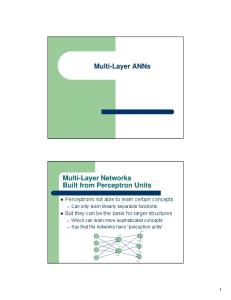
BGP state machine
In order to make decisions in its operations with other BGP peers, a BGP peer uses a simple finite state machine (FSM) that consists of six states: Idle; Connect; Active; OpenSent; OpenConfirm; and Established. For each peer-to-peer session, a BGP implementation maintains a state variable that tracks which of these six states the session is in. The BGP protocol defines the messages that each peer should exchange in order to change the session from one state to another. The first state is the “Idle” state. In the “Idle” state, BGP initializes all resources, refuses all inbound BGP connection attempts and initiates a TCP connection to the peer. The second state is “Connect”. In the “Connect” state, the router waits for the TCP connection to complete and transitions to the "OpenSent" state if successful. If unsuccessful, it resets the ConnectRetry timer and transitions to the "Active" state upon expiration. In the "Active" state, the router resets the ConnectRetry timer to zero and returns to the "Connect" state. In the "OpenSent" state, the router sends an Open message and waits for one in return. Keepalive messages are exchanged and, upon successful receipt, the router is placed into the “Established” state. In the “Established” state, the router can send/receive: Keepalive; Update; and Notification messages to/from its peer.
•
•
•
•
•
•
Idle State: o Refuse all incoming BGP connections o Start event triggers the initialization of resources for the BGP process. o Initiates a TCP connection with its configured BGP peer. o Listens for a TCP connection from its peer. o Changes its state to Connect. o If an error occurs at any state of the FSM process, the BGP session is terminated immediately and returned to the Idle state. Some of the reasons why a router does not progress from the Idle state are: TCP port 179 is not open. A random TCP port over 1023 is not open. Peer address configured incorrectly on either router. AS number configured incorrectly on either router . Connect State: o Waits for successful TCP negotiation with peer. o BGP does not spend much time in this state if the TCP session has been successfully established. o Sends Open message to peer and changes state to OpenSent. o If an error occurs, BGP moves to the Active state. Some reasons for the error are: TCP port 179 is not open. A random TCP port over 1023 is not open. Peer address configured incorrectly on either router. AS number configured incorrectly on either router. Active State: o If the router was unable to establish a successful TCP session, then it ends up in the Active state. o BGP FSM will try to restart another TCP session with the peer and, if successful, then it will send an Open message to the peer. o If it is unsuccessful again, the FSM is reset to the Idle state. o Repeated failures may result in a router cycling between the Idle and Active states. Some of the reasons for this include: TCP port 179 is not open. A random TCP port over 1023 is not open. BGP configuration error. Network congestion. Flapping network interface. OpenSent State: o BGP FSM listens for an Open message from its peer. o Once the message has been received, the router checks the validity of the Open message. o If there is an error it is because one of the fields in the Open message doesn’t match between the peers, e.g. BGP version mismatch, MD5 password mismatch, the peering router expects a different My AS. The router will then send a Notification message to the peer indicating why the error occurred. o If there is no error, a Keepalive message is sent, various timers are set and the state is changed to OpenConfirm. OpenConfirm State: o The peer is listening for a Keepalive message from its peer. o If a Keepalive message is received and no timer has expired before reception of the Keepalive, BGP transitions to the Established state. o If a timer expires before a Keepalive message is received, or if an error condition occurs, the router transitions back to the Idle state. Established State: o In this state, the peers send Update messages to exchange information about each route being advertised to the BGP peer. o If there is any error in the Update message then a Notification message is sent to the peer, and BGP transitions back to the Idle state.
o
If a timer expires before a Keepalive message is received, or if an error condition occurs, the router transitions back to the Idle state.
1.1.3 Basic BGP updates
Once a BGP session is running, the BGP speakers exchange UPDATE messages about destinations to which the speaker offers connectivity. In the protocol, the basic CIDR route description is called Network Layer Reachability Information (NLRI). NLRI includes the expected destination prefix, prefix length, path of autonomous systems to the destination and next hop in attributes, which can carry a wide range of additional information that affects the acceptance policy of the receiving router. BGP speakers incrementally announce new NLRI to which they offer reachability, but also announce withdrawals of prefixes to which the speaker no longer offers connectivity. 1.2 BGP router connectivity and learning routes
In the simplest arrangement all routers within a single AS and participating in BGP routing must be configured in a full mesh: each router must be configured as peer to every other router. This causes scaling problems, since the number of required connections grows quadratically with the number of routers involved. To alleviate the problem, BGP implements two options: route reflectors (RFC 4456) and confederations (RFC 5065). The following discussion of basic UPDATE processing assumes a full IBGP mesh. 1.2.1 Basic update processing
A given BGP router may accept NLRI in UPDATEs from multiple neighbors and advertise NLRI to the same, or a different set, of neighbors. Conceptually, BGP maintains its own "master" routing table, called the Loc-RIB (Local Routing Information Base), separate from the main routing table of the router. For each neighbor, the BGP process maintains a conceptual AdjRIB-In (Adjacent Routing Information Base, Incoming) containing the NLRI received from the neighbor, and a conceptual Adj-RIB-Out (Outgoing) for NLRI to be sent to the neighbor. Conceptual, in the preceding paragraph, means that the physical storage and structure of these various tables are decided by the implementer of the BGP code. Their structure is not visible to other BGP routers, although they usually can be interrogated with management commands on the local router. It is quite common, for example, to store the two Adj-RIBs and the Loc-RIB together in the same data structure, with additional information attached to the RIB entries. The additional information tells the BGP process such things as whether individual entries belong in the Adj-RIBs for specific neighbors, whether the per-neighbor route selection process made received policies eligible for the Loc-RIB, and whether Loc-RIB entries are eligible to be submitted to the local router's routing table management process. By eligible to be submitted, BGP will submit the routes that it considers best to the main routing table process. Depending on the implementation of that process, the BGP route is not necessarily selected. For example, a directly connected prefix, learned from the router's own hardware, is usually most preferred. As long as that directly connected route's interface is active, the BGP route to the destination will not be put into the routing table. Once the interface goes down, and
there are no more preferred routes, the Loc-RIB route would be installed in the main routing table. Until recently, it was a common mistake to say BGP carries policies. BGP actually carried the information with which rules inside BGP-speaking routers could make policy decisions. Some of the information carried that is explicitly intended to be used in policy decisions are communities and multi-exit discriminators (MED). 1.2.2 Route selection
The BGP standard specifies a number of decision factors, more than are used by any other common routing process, for selecting NLRI (Network Layer Reachability Information) to go into the Loc-RIB (Routing Information Base). The first decision point for evaluating NLRI is that its next-hop attribute must be reachable (or resolvable). Another way of saying the next-hop must be reachable is that there must be an active route, already in the main routing table of the router, to the prefix in which the next-hop address is located. Next, for each neighbor, the BGP process applies various standard and implementationdependent criteria to decide which routes conceptually should go into the Adj-RIB-In. The neighbor could send several possible routes to a destination, but the first level of preference is at the neighbor level. Only one route to each destination will be installed in the conceptual AdjRIB-In. This process will also delete, from the Adj-RIB-In, any routes that are withdrawn by the neighbor. Whenever a conceptual Adj-RIB-In changes, the main BGP process decides if any of the neighbor's new routes are preferred to routes already in the Loc-RIB. If so, it replaces them. If a given route is withdrawn by a neighbor, and there is no other route to that destination, the route is removed from the Loc-RIB, and no longer sent, by BGP, to the main routing table manager. If the router does not have a route to that destination from any non-BGP source, the withdrawn route will be removed from the main routing table. 1.2.2.1 Per-neighbor decisions
After verifying that the next hop is reachable, if the route comes from an internal (i.e. IBGP) peer, the first rule to apply according to the standard is to examine the LOCAL_PREF attribute. If there are several IBGP routes from the neighbor, the one with the highest LOCAL_PREF is selected unless there are several routes with the same LOCAL_PREF. In the latter case the route selection process moves to the next tie breaker. While LOCAL_PREF is the first rule in the standard, once reachability of the NEXT_HOP is verified, Cisco and several other vendors first consider a decision factor called WEIGHT which is local to the router (i.e. not transmitted by BGP). The route with the highest WEIGHT is preferred. LOCAL_PREF, WEIGHT, and other criteria can be manipulated by local configuration and software capabilities. Such manipulation is outside the scope of the standard but is commonly used. For example the COMMUNITY attribute (see below) is not directly used by the BGP selection process. The BGP neighbor process however can have a rule to set LOCAL_PREFERENCE or another factor based on a manually programmed rule to set the attribute if the COMMUNITY value matches some pattern matching criterion. If the route was
learned from an external peer the per-neighbor BGP process computes a LOCAL_PREFERENCE value from local policy rules and then compares the LOCAL_PREFERENCE of all routes from the neighbor. At the per-neighbor level - ignoring implementation-specific policy modifiers - the order of tie breaking rules is: 1. 2. 3.
Prefer the route with the shortest AS_PATH. An AS_PATH is the set of AS numbers that must be traversed to reach the advertised destination. AS1-AS2-AS3 is shorter than AS4-AS5-AS6-AS7. Prefer routes with the lowest value of their ORIGIN attribute. Prefer routes with the lowest MULTI_EXIT_DISC (multi-exit discriminator or MED) value.
Before the most recent edition of the BGP standard, if an UPDATE had no MULTI_EXIT_DISC value, several implementations created a MED with the least possible value. The current standard however specifies that missing MEDs are to be treated as the highest possible value. Since the current rule may cause different behavior than the vendor interpretations, BGP implementations that used the nonstandard default value have a configuration feature that allows the old or standard rule to be selected. 1.2.2.2 Decision factors at the Loc-RIB level
Once candidate routes are received from neighbors, the Loc-RIB software applies additional tiebreakers to routes to the same destination. 1. 2.
If at least one route was learned from an external neighbor (i.e., the route was learned from EBGP), drop all routes learned from IBGP. Prefer the route with the lowest interior cost to the NEXT_HOP, according to the main Routing Table. If two neighbors advertised the same route, but one neighbor is reachable via a low-bitrate link and the other by a high-bitrate link, and the interior routing protocol calculates lowest cost based on highest bitrate, the route through the high-bitrate link would be preferred and other routes dropped.
If there is more than one route still tied at this point, several BGP implementations offer a configurable option to load-share among the routes, accepting all (or all up to some number). 1. 2.
Prefer the route learned from the BGP speaker with the numerically lowest BGP identifier Prefer the route learned from the BGP speaker with the lowest peer IP address
1.2.3 Communities
BGP communities are attribute tags that can be applied to incoming or outgoing prefixes to achieve some common goal (RFC 1997). While it is common to say that BGP allows an administrator to set policies on how prefixes are handled by ISPs, this is generally not possible, strictly speaking. For instance, BGP natively has no concept to allow one AS to tell another AS to restrict advertisement of a prefix to only North American peering customers. Instead, an ISP generally publishes a list of well-known or proprietary communities with a description for each one, which essentially becomes an agreement of how prefixes are to be treated. Examples of common communities include local preference adjustments, geographic or peer type restrictions, DoS avoidance (black holing), and AS prepending options. An ISP might state that any routes
received from customers with community XXX:500 will be advertised to all peers (default) while community XXX:501 will restrict advertisement to North America. The customer simply adjusts their configuration to include the correct community(ies) for each route, and the ISP is responsible for controlling who the prefix is advertised to. The end user has no technical ability to enforce correct actions being taken by the ISP, though problems in this area are generally rare and accidental. It is a common tactic for end customers to use BGP communities (usually ASN:70,80,90,100) to control the local preference the ISP assigns to advertised routes instead of using MED (the effect is similar). It should also be noted that the community attribute is transitive, but communities applied by the customer very rarely become propagated outside the next-hop AS. 1.2.4 Extended communities
The BGP Extended Community Attribute was added in 2006 in order to extend the range of such attributes and to provide a community attribute structuring by means of a type field. The extended format consists of one or two octets for the type field followed by seven or six octets for the respective community attribute content. The definition of this Extended Community Attribute is documented in RFC 4360. The IANA administers the registry for BGP Extended Communities Types.[4] The Extended Communities Attribute itself is a transitive optional BGP attribute. However, a bit in the type field within the attribute decides whether the encoded extended community is of a transitive or non-transitive nature. The IANA registry therefore provides different number ranges for the attribute types. Due to the extended attribute range, its usage can be manifold. RFC 4360 exemplarly defines the "Two-Octet AS Specific Extended Community", the "IPv4 Address Specific Extended Community", the "Opaque Extended Community", the "Route Target Community" and the "Route Origin Community". A number of BGP QoS drafts[5] also use this Extended Community Attribute structure for inter-domain QoS signalling. 1.2.5 Uses of multi-exit discriminators
MEDs, defined in the main BGP standard, were originally intended to show to another neighbor AS the advertising AS's preference as to which of several links are preferred for inbound traffic. Another application of MEDs is to advertise the value, typically based on delay, of multiple AS that have presence at an IXP, that they impose to send traffic to some destination. 1.3 BGP problems and mitigation 1.3.1 Internal BGP scalability
An autonomous system with internal BGP (IBGP) must have all of its IBGP peers connect to each other in a full mesh (where everyone speaks to everyone directly). This full-mesh configuration requires that each router maintain a session to every other router. In large networks, this number of sessions may degrade performance of routers, due either to a lack of memory, or too much CPU process requirements.
Route reflectors and confederations both reduce the number of IBGP peers to each router and thus reduce processing overhead. Route reflectors are a pure performance-enhancing technique, while confederations also can be used to implement more fine-grained policy. Route reflectors[6] reduce the number of connections required in an AS. A single router (or two for redundancy) can be made a route reflector: other routers in the AS need only be configured as peers to them. Confederations are sets of autonomous systems. In common practice,[7] only one of the confederation AS numbers is seen by the Internet as a whole. Confederations are used in very large networks where a large AS can be configured to encompass smaller more manageable internal ASs. Confederations can be used in conjunction with route reflectors. Both confederations and route reflectors can be subject to persistent oscillation unless specific design rules, affecting both BGP and the interior routing protocol, are followed.[8] However, these alternatives can introduce problems of their own, including the following: • • •
route oscillation sub-optimal routing increase of BGP convergence time[9]
Additionally, route reflectors and BGP confederations were not designed to ease BGP router configuration. Nevertheless, these are common tools for experienced BGP network architects. These tools may be combined, for example, as a hierarchy of route reflectors. 1.3.2 Instability
The routing tables managed by a BGP implementation are adjusted continually to reflect actual changes in the network, such as links breaking and being restored or routers going down and coming back up. In the network as a whole it is normal for these changes to happen almost continuously, but for any particular router or link changes are supposed to be relatively infrequent. If a router is misconfigured or mismanaged then it may get into a rapid cycle between down and up states. This pattern of repeated withdrawal and reannouncement, known as route flapping, can cause excessive activity in all the other routers that know about the broken link, as the same route is continuously injected and withdrawn from the routing tables. The BGP design is such that delivery of traffic may not function while routes are being updated. On the Internet, a BGP routing change may cause outages for several minutes. A feature known as route flap damping (RFC 2439) is built into many BGP implementations in an attempt to mitigate the effects of route flapping. Without damping the excessive activity can cause a heavy processing load on routers, which may in turn delay updates on other routes, and so affect overall routing stability. With damping, a route's flapping is exponentially decayed. At the first instance when a route becomes unavailable and quickly reappears, damping does not take effect, so as to maintain the normal fail-over times of BGP. At the second occurrence, BGP shuns that prefix for a certain length of time; subsequent occurrences are timed out
exponentially. After the abnormalities have ceased and a suitable length of time has passed for the offending route, prefixes can be reinstated and its slate wiped clean. Damping can also mitigate denial of service attacks; damping timings are highly customizable. However, subsequent research has shown that flap damping can actually lengthen convergence times in some cases, and can cause interruptions in connectivity even when links are not flapping.[10][11] Moreover, as backbone links and router processors have become faster, some network architects have suggested that flap damping may not be as important as it used to be, since changes to the routing table can be absorbed much faster by routers.[citation needed] This has led the RIPE Route Working Group to write that "with the current implementations of BGP flap damping, the application of flap damping in ISP networks is NOT recommended. ... If flap damping is implemented, the ISP operating that network will cause side-effects to their customers and the Internet users of their customers' content and services ... . These side-effects would quite likely be worse than the impact caused by simply not running flap damping at all." [1] Improving stability without the problems of flap damping is the subject of current research.[2] 1.3.3 Routing table growth
BGP table growth on the Internet.
Number of AS on the Internet.
One of the largest problems faced by BGP, and indeed the Internet infrastructure as a whole, is the growth of the Internet routing table. If the global routing table grows to the point where some older, less capable, routers cannot cope with the memory requirements or the CPU load of maintaining the table, these routers will cease to be effective gateways between the parts of the Internet they connect. In addition, and perhaps even more importantly, larger routing tables take
longer to stabilize (see above) after a major connectivity change, leaving network service unreliable, or even unavailable, in the interim. Until late 2001, the global routing table was growing exponentially, threatening an eventual widespread breakdown of connectivity. In an attempt to prevent this, ISPs cooperated in keeping the global routing table as small as possible, by using Classless Inter-Domain Routing (CIDR) and route aggregation. While this slowed the growth of the routing table to a linear process for several years, with the expanded demand for multihoming by end user networks the growth was once again exponential by the middle of 2004. As of April 2010, the routing table has in excess of 310,000 entries.[12] Route summarization is often used to improve aggregation of the BGP global routing table, thereby reducing the necessary table size in routers of an AS. Consider AS1 has been allocated the big address space of 172.16.0.0/16, this would be counted as one route in the table, but due to customer requirement or traffic engineering purposes, AS1 wants to announce smaller, more specific routes of 172.16.0.0/18, 172.16.64.0/18 and 172.16.128.0/18. The prefix 172.16.192.0/18 does not have any hosts so AS1 does not announce a specific route 172.16.192.0/18. This all counts as AS1 announcing four routes. AS2 will see the 4 routes from AS1 (172.16.0.0/16, 172.16.0.0/18, 172.16.64.0/18 and 172.16.128.0/18) and it is up to the routing policy of AS2 to decide whether or not to take a copy of the four routes or, as 172.16.0.0/16 overlaps all the other specific routes, to just store the summary, 172.16.0.0/16. If AS2 wants to send data to prefix 172.16.192.0/18, it will be sent to the routers of AS1 on route 172.16.0.0/16. At AS1's router, it will either be dropped or a destination unreachable ICMP message will be sent back, depending on the configuration of AS1's routers. If AS1 later decides to drop the route 172.16.0.0/16, leaving 172.16.0.0/18, 172.16.64.0/18 and 172.16.128.0/18, AS1 will drop the number of routes it announces to three. AS2 will see the three routes, and depending on the routing policy of AS2, it will store a copy of the three routes, or aggregate the prefix's 172.16.0.0/18 and 172.16.64.0/18 to 172.16.0.0/17, thereby reducing the number of routes AS2 stores to only two: 172.16.0.0/17 and 172.16.128.0/18. If AS2 wants to send data to prefix 172.16.192.0/18, it will be dropped or a destination unreachable ICMP message will be sent back at the routers of AS2 (not AS1 as before), because 172.16.192.0/18 would not be in the routing table. 1.3.4 Load-balancing problem
Another factor causing this growth of the routing table is the need for load balancing of multihomed networks. It is not a trivial task to balance the inbound traffic to a multi-homed network across its multiple inbound paths, due to limitation of the BGP route selection process. For a multi-homed network, if it announces the same network blocks across all of its BGP peers, the result may be that one or several of its inbound links become congested while the other links
remain under-utilized, because external networks all picked that set of congested paths as optimal. Like most other routing protocols, the BGP protocol does not detect congestion. To work around this problem, BGP administrators of that multihomed network may divide a large continuous IP address block into smaller blocks, and tweak the route announcement to make different blocks look optimal on different paths, so that external networks will choose a different path to reach different blocks of that multi-homed network. Such cases will increase the number of routes as seen on the global BGP table. 1.4 Requirements of a router for use of BGP for Internet and backbone-ofbackbones purposes
Routers, especially small ones intended for Small Office/Home Office (SOHO) use, may not include BGP software. Some SOHO routers simply are not capable of running BGP using BGP routing tables of any size. Other commercial routers may need a specific software executable image that contains BGP, or a license that enables it. Open source packages that run BGP include GateD, GNU Zebra, Quagga, OpenBGPD, BIRD, XORP and Vyatta. Devices marketed as Layer 3 switches are less likely to support BGP than devices marketed as routers, but high-end Layer 3 Switches usually can run BGP. Products marketed as switches may or may not have a size limitation on BGP tables, such as 20,000 routes, far smaller than a full Internet table plus internal routes. These devices, however, may be perfectly reasonable and useful when used for BGP routing of some smaller part of the network, such as a confederation-AS representing one of several smaller enterprises that are linked, by a BGP backbone of backbones, or a small enterprise that announces routes to an ISP but only accepts a default route and perhaps a small number of aggregated routes. A BGP router used only for a network with a single point of entry to the Internet may have a much smaller routing table size (and hence RAM and CPU requirement) than a multihomed network. Even simple multihoming can have modest routing table size. See RFC 4098 for vendor-independent performance parameters for single BGP router convergence in the control plane. The actual amount of memory required in a BGP router depends on the amount of BGP information exchanged with other BGP speakers, and the way in which the particular router stores BGP information. The router may have to keep more than one copy of a route, so it can manage different policies for route advertising and acceptance to a specific neighboring AS. The term view is often used for these different policy relationships on a running router. If one router implementation takes more memory per route than another implementation, this may be a legitimate design choice, trading processing speed against memory. A full BGP table as of April 2010 is in excess of 310,000 prefixes. Large ISPs may add another 50% for internal and customer routes. Again depending on implementation, separate tables may be kept for each view of a different peer AS.
2. DHCP The Dynamic Host Configuration Protocol (DHCP) is an auto configuration protocol used on IP networks. Computers that are connected to IP networks must be configured before they can communicate with other computers on the network. DHCP allows a computer to be configured automatically, eliminating the need for intervention by a network administrator. It also provides a central database for keeping track of computers that have been connected to the network. This prevents two computers from accidentally being configured with the same IP address. In the absence of DHCP, hosts may be manually configured with an IP address. Alternatively IPv6 hosts may use stateless address autoconfiguration to generate an IP address. IPv4 hosts may use link-local addressing to achieve limited local connectivity. In addition to IP addresses, DHCP also provides other configuration information, particularly the IP addresses of local caching DNS resolvers. Hosts that do not use DHCP for address configuration may still use it to obtain other configuration information. There are two versions of DHCP, one for IPv4 and one for IPv6. While both versions bear the same name and perform much the same purpose, the details of the protocol for IPv4 and IPv6 are sufficiently different that they can be considered separate protocols.[1] 2.1 History
DHCP was first defined as a standards track protocol in RFC 1531 in October 1993, as an extension to the Bootstrap Protocol (BOOTP). The motivation for extending BOOTP was that BOOTP required manual intervention to add configuration information for each client, and did not provide a mechanism for reclaiming disused IP addresses. Much work was done to clarify the protocol as it gained popularity, and in 1997 RFC 2131 was released, and remains as of 2011 the standard for IPv4 networks. DHCPv6 is documented in RFC 3315. RFC 3633 added a DHCPv6 mechanism for prefix delegation. DHCPv6 was further extended to provide configuration information to clients configured using stateless address autoconfiguration in RFC 3736. The BOOTP protocol itself was first defined in RFC 951 as a replacement for the Reverse Address Resolution Protocol RARP. The primary motivation for replacing RARP with BOOTP was that RARP was a data link layer protocol. This made implementation difficult on many server platforms, and required that a server be present on each individual network link. BOOTP introduced the innovation of a relay agent, which allowed the forwarding of BOOTP packets off the local network using standard IP routing, thus one central BOOTP server could serve hosts on many IP subnets.[2]
2.2 Technical overview
Dynamic Host Configuration Protocol automates network-parameter assignment to network devices from one or more DHCP servers. Even in small networks, DHCP is useful because it makes it easy to add new machines to the network. When a DHCP-configured client (a computer or any other network-aware device) connects to a network, the DHCP client sends a broadcast query requesting necessary information from a DHCP server. The DHCP server manages a pool of IP addresses and information about client configuration parameters such as default gateway, domain name, the name servers, other servers such as time servers, and so forth. On receiving a valid request, the server assigns the computer an IP address, a lease (length of time the allocation is valid), and other IP configuration parameters, such as the subnet mask and the default gateway. The query is typically initiated immediately after booting, and must complete before the client can initiate IP-based communication with other hosts. Depending on implementation, the DHCP server may have three methods of allocating IPaddresses: •
•
•
dynamic allocation: A network administrator assigns a range of IP addresses to DHCP, and each client computer on the LAN is configured to request an IP address from the DHCP server during network initialization. The request-and-grant process uses a lease concept with a controllable time period, allowing the DHCP server to reclaim (and then reallocate) IP addresses that are not renewed. automatic allocation: The DHCP server permanently assigns a free IP address to a requesting client from the range defined by the administrator. This is like dynamic allocation, but the DHCP server keeps a table of past IP address assignments, so that it can preferentially assign to a client the same IP address that the client previously had. static allocation: The DHCP server allocates an IP address based on a table with MAC address/IP address pairs, which are manually filled in (perhaps by a network administrator). Only requesting clients with a MAC address listed in this table will be allocated an IP address. This feature (which is not supported by all DHCP servers) is variously called Static DHCP Assignment (by DD-WRT), fixed-address (by the dhcpd documentation), Address Reservation (by Netgear), DHCP reservation or Static DHCP (by Cisco/Linksys), and IP reservation or MAC/IP binding (by various other router manufacturers).
2.3 Technical details
DHCP uses the same two ports assigned by IANA for BOOTP: UDP port 67 for sending data to the server, and UDP port 68 for data to the client. DHCP communications are connectionless in nature. DHCP operations fall into four basic phases: IP discovery, IP lease offer, IP request, and IP lease acknowledgement. DHCP clients and servers on the same subnet communicate via UDP broadcasts. If the client and server are on different subnets, IP discovery and IP request messages are sent via UDP broadcasts, but IP lease offer and IP lease acknowledgement messages are unicast.
2.3.1 DHCP discovery
The client broadcasts messages on the physical subnet to discover available DHCP servers. Network administrators can configure a local router to forward DHCP packets to a DHCP server from a different subnet. This client-implementation creates a User Datagram Protocol (UDP) packet with the broadcast destination of 255.255.255.255 or the specific subnet broadcast address. A DHCP client can also request its last-known IP address (in the example below, 192.168.1.100). If the client remains connected to a network for which this IP is valid, the server might grant the request. Otherwise, it depends whether the server is set up as authoritative or not. An authoritative server will deny the request, making the client ask for a new IP address immediately. A non-authoritative server simply ignores the request, leading to an implementation-dependent timeout for the client to give up on the request and ask for a new IP address. DHCPDISCOVER UDP Src=0.0.0.0 sPort=68 Dest=255.255.255.255 dPort=67 OP HTYPE HLEN HOPS 0x01 0x01 0x06 0x00 XID 0x3903F326 SECS FLAGS 0x0000 0x0000 CIADDR 0x00000000 YIADDR 0x00000000 SIADDR 0x00000000 GIADDR 0x00000000 CHADDR 0x00053C04 0x8D590000 0x00000000 0x00000000 192 octets of 0's. BOOTP legacy Magic Cookie 0x63825363 DHCP Options DHCP option 53: DHCP Discover DHCP option 50: 192.168.1.100 requested DHCP option 55: Parameter Request List:
Request Subnet Mask (1), Router (3), Domain Name (15), Domain Name Server (6)
2.3.2 DHCP offer
When a DHCP server receives an IP lease request from a client, it reserves an IP address for the client and extends an IP lease offer by sending a DHCPOFFER message to the client. This message contains the client's MAC address, the IP address that the server is offering, the subnet mask, the lease duration, and the IP address of the DHCP server making the offer. The server determines the configuration based on the client's hardware address as specified in the CHADDR (Client Hardware Address) field. Here the server, 192.168.1.1, specifies the IP address in the YIADDR (Your IP Address) field. DHCPOFFER UDP Src=192.168.1.1 sPort=67 Dest=255.255.255.255 dPort=68 OP HTYPE HLEN HOPS 0x02 0x01 0x06 0x00 XID 0x3903F326 SECS FLAGS 0x0000 0x0000 CIADDR 0x00000000 YIADDR 0xC0A80164 SIADDR 0xC0A80101 GIADDR 0x00000000 CHADDR 0x00053C04 0x8D590000 0x00000000 0x00000000 192 octets of 0's. BOOTP legacy Magic Cookie 0x63825363 DHCP Options DHCP option 53: DHCP Offer DHCP option 1: 255.255.255.0 subnet mask DHCP option 3: 192.168.1.1 router
DHCP option 51: 86400s (1 day) IP lease time DHCP option 54: 192.168.1.1 DHCP server DHCP option 6: DNS servers 9.7.10.15, 9.7.10.16, 9.7.10.18
2.3.3 DHCP request
A client can receive DHCP offers from multiple servers, but it will accept only one DHCP offer and broadcast a DHCP request message. Based on the Transaction ID field in the request, servers are informed whose offer the client has accepted. When other DHCP servers receive this message, they withdraw any offers that they might have made to the client and return the offered address to the pool of available addresses. The DHCP request message is broadcast, instead of being unicast to a particular DHCP server, because the DHCP client has still not received an IP address. Also, this way one message can let all other DHCP servers know that another server will be supplying the IP address without missing any of the servers with a series of unicast messages. DHCPREQUEST UDP Src=0.0.0.0 sPort=68 Dest=255.255.255.255 dPort=67 OP HTYPE HLEN HOPS 0x01 0x01 0x06 0x00 XID 0x3903F326 SECS FLAGS 0x0000 0x0000 CIADDR 0x00000000 YIADDR 0x00000000 SIADDR 0xC0A80101 GIADDR 0x00000000 CHADDR 0x00053C04 0x8D590000 0x00000000 0x00000000 192 octets of 0's. BOOTP legacy Magic Cookie 0x63825363 DHCP Options DHCP option 53: DHCP Request DHCP option 50: 192.168.1.100 requested DHCP option 54: 192.168.1.1 DHCP server.
2.3.4 DHCP acknowledgement
When the DHCP server receives the DHCPREQUEST message from the client, the configuration process enters its final phase. The acknowledgement phase involves sending a DHCPACK packet to the client. This packet includes the lease duration and any other configuration information that the client might have requested. At this point, the IP configuration process is completed. The protocol expects the DHCP client to configure its network interface with the negotiated parameters. DHCPACK UDP Src=192.168.1.1 sPort=67 Dest=255.255.255.255 dPort=68 OP HTYPE HLEN HOPS 0x02 0x01 0x06 0x00 XID 0x3903F326 SECS FLAGS 0x0000 0x0000 CIADDR (Client IP Address) 0x00000000 YIADDR (Your IP Address) 0xC0A80164 SIADDR (Server IP Address) 0xC0A80101 GIADDR (Gateway IP Address switched by relay) 0x00000000 CHADDR (Client Hardware Address) 0x00053C04 0x8D590000 0x00000000 0x00000000 192 octets of 0's. BOOTP legacy Magic Cookie 0x63825363 DHCP Options DHCP option 53: DHCP ACK DHCP option 1: 255.255.255.0 subnet mask DHCP option 3: 192.168.1.1 router DHCP option 51: 86400s (1 day) IP lease time DHCP option 54: 192.168.1.1 DHCP server DHCP option 6: DNS servers 9.7.10.15, 9.7.10.16, 9.7.10.18
After the client obtains an IP address, the client may use the Address Resolution Protocol (ARP) to prevent IP conflicts caused by overlapping address pools of DHCP servers. 2.3.5 DHCP information
A DHCP client may request more information than the server sent with the original DHCPOFFER. The client may also request repeat data for a particular application. For example, browsers use DHCP Inform to obtain web proxy settings via WPAD. Such queries do not cause the DHCP server to refresh the IP expiry time in its database. 2.3.6 DHCP releasing
The client sends a request to the DHCP server to release the DHCP information and the client deactivates its IP address. As client devices usually do not know when users may unplug them from the network, the protocol does not mandate the sending of DHCP Release. 2.3.7 Client configuration parameters in DHCP
A DHCP server can provide optional configuration parameters to the client. RFC 2132 describes the available DHCP options defined by Internet Assigned Numbers Authority (IANA) - DHCP and BOOTP PARAMETERS. A DHCP client can select, manipulate and overwrite parameters provided by a DHCP server.[3] 2.3.8 Options
An option exists to identify the vendor and functionality of a DHCP client. The information is a variable-length string of characters or octets which has a meaning specified by the vendor of the DHCP client. One method that a DHCP client can utilize to communicate to the server that it is using a certain type of hardware or firmware is to set a value in its DHCP requests called the Vendor Class Identifier (VCI) (Option 60). This method allows a DHCP server to differentiate between the two kinds of client machines and process the requests from the two types of modems appropriately. Some types of set-top boxes also set the VCI (Option 60) to inform the DHCP server about the hardware type and functionality of the device. The value that this option is set to gives the DHCP server a hint about any required extra information that this client needs in a DHCP response. 2.3.9 DHCP Relaying
In small networks, where only one IP subnet is being managed, DHCP clients communicate directly with DHCP servers. However, DHCP servers can also provide IP addresses for multiple subnets. In this case, a DHCP client that has not yet acquired an IP address cannot communicate directly with the DHCP server using IP routing, because it doesn't have a routable IP address, nor does it know the IP address of a router. In order to allow DHCP clients on subnets not directly served by DHCP servers to communicate with DHCP servers, DHCP relay agents can be installed on these subnets. The DHCP client broadcasts on the local link; the relay agent receives
the broadcast and transmits it to one or more DHCP servers using unicast. The relay agent stores its own IP address in the GIADDR field of the DHCP packet. The DHCP server uses the GIADDR to determine the subnet on which the relay agent received the broadcast, and allocates an IP address on that subnet. When the DHCP server replies to the client, it sends the reply to the GIADDR address, again using unicast. The relay agent then retransmits the response on the local network. 2.3.10 Reliability
The DHCP protocol provides reliability in several ways: periodic renewal, rebinding, and failover. DHCP clients are allocated leases that last for some period of time. Clients begin to attempt to renew their leases once half the lease interval has expired. They do this by sending a unicast DHCPREQUEST message to the DHCP server that granted the original lease. If that server is down or unreachable, it will fail to respond to the DHCPREQUEST. However, the DHCPREQUEST will be repeated by the client from time to time,[specify] so when the DHCP server comes back up or becomes reachable again, the DHCP client will succeed in contacting it, and renew its lease. If the DHCP server is unreachable for an extended period of time,[specify] the DHCP client will attempt to rebind, by broadcasting its DHCPREQUEST rather than unicasting it. Because it is broadcast, the DHCPREQUEST message will reach all available DHCP servers. If some other DHCP server is able to renew the lease, it will do so at this time. In order for rebinding to work, when the client successfully contacts a backup DHCP server, that server must have accurate information about the client's binding. Maintaining accurate binding information between two servers is a complicated problem; if both servers are able to update the same lease database, there must be a mechanism to avoid conflicts between updates on the independent servers. A standard for implementing fault-tolerant DHCP servers was developed at the Internet Engineering Task Force.[4][note 1] If rebinding fails, the lease will eventually expire. When the lease expires, the client must stop using the IP address granted to it in its lease. At that time, it will restart the DHCP process from the beginning by broadcasting a DHCPDISCOVER message. Since its lease has expired, it will accept any IP address offered to it. Once it has a new IP address, presumably from a different DHCP server, it will once again be able to use the network. However, since its IP address has changed, any ongoing connections will be broken. 2.4 Security
The base DHCP protocol does not include any mechanism for authentication.[5] Because of this, it is vulnerable to a variety of attacks. These attacks fall into three main categories: • • •
Unauthorized DHCP servers providing false information to clients.[6] Unauthorized clients gaining access to resources.[6] Resource exhaustion attacks from malicious DHCP clients.[6]
Because the client has no way to validate the identity of a DHCP server, unauthorized DHCP servers can be operated on networks, providing incorrect information to DHCP clients. This can serve either as a denial-of-service attack, preventing the client from gaining access to network connectivity[citation needed], or as a man-in-the-middle attack. Because the DHCP server provides the DHCP client with server IP addresses, such as the IP address of one or more DNS servers,[6] an attacker can convince a DHCP client to do its DNS lookups through its own DNS server, and can therefore provide its own answers to DNS queries from the client[citation needed]. This in turn allows the attacker to redirect network traffic through itself, allowing it to eavesdrop on connections between the client and network servers it contacts, or to simply replace those network servers with its own.[citation needed] Because the DHCP server has no secure mechanism for authenticating the client, clients can gain unauthorized access to IP addresses by presenting credentials, such as client identifiers, that belong to other DHCP clients.[citation needed] This also allows DHCP clients to exhaust the DHCP server's store of IP addresses—by presenting new credentials each time it asks for an address, the client can consume all the available IP addresses on a particular network link, preventing other DHCP clients from getting service.[citation needed] DHCP does provide some mechanisms for mitigating these problems. The Relay Agent Information Option protocol extension (RFC 3046) allows network operators to attach tags to DHCP messages as these messages arrive on the network operator's trusted network. This tag is then used as an authorization token to control the client's access to network resources. Because the client has no access to the network upstream of the relay agent, the lack of authentication does not prevent the DHCP server operator from relying on the authorization token.[5] Another extension, Authentication for DHCP Messages (RFC 3118), provides a mechanism for authenticating DHCP messages. Unfortunately RFC 3118 has not seen widespread adoption because of the problems of managing keys for large numbers of DHCP clients.[7] 3. DNS The Domain Name System (DNS) is a hierarchical naming system built on a distributed database for computers, services, or any resource connected to the Internet or a private network. It associates various information with domain names assigned to each of the participating entities. Most importantly, it translates domain names meaningful to humans into the numerical identifiers associated with networking equipment for the purpose of locating and addressing these devices worldwide. An often-used analogy to explain the Domain Name System is that it serves as the phone book for the Internet by translating human-friendly computer hostnames into IP addresses. For example, the domain name www.example.com translates to the addresses 192.0.32.10 (IPv4) and 2620:0:2d0:200::10 (IPv6). The Domain Name System makes it possible to assign domain names to groups of Internet resources and users in a meaningful way, independent of each entity's physical location. Because of this, World Wide Web (WWW) hyperlinks and Internet contact information can remain
consistent and constant even if the current Internet routing arrangements change or the participant uses a mobile device. Internet domain names are easier to remember than IP addresses such as 208.77.188.166 (IPv4) or 2001:db8:1f70::999:de8:7648:6e8 (IPv6). Users take advantage of this when they recite meaningful Uniform Resource Locators (URLs) and e-mail addresses without having to know how the computer actually locates them. The Domain Name System distributes the responsibility of assigning domain names and mapping those names to IP addresses by designating authoritative name servers for each domain. Authoritative name servers are assigned to be responsible for their particular domains, and in turn can assign other authoritative name servers for their sub-domains. This mechanism has made the DNS distributed and fault tolerant and has helped avoid the need for a single central register to be continually consulted and updated. In general, the Domain Name System also stores other types of information, such as the list of mail servers that accept email for a given Internet domain. By providing a worldwide, distributed keyword-based redirection service, the Domain Name System is an essential component of the functionality of the Internet. Other identifiers such as RFID tags, UPC codes, International characters in email addresses and host names, and a variety of other identifiers could all potentially use DNS.[1][2] The Domain Name System also specifies the technical functionality of this database service. It defines the DNS protocol, a detailed definition of the data structures and communication exchanges used in DNS, as part of the Internet Protocol Suite. 3.1 Overview
The Internet maintains two principal namespaces, the domain name hierarchy[3] and the Internet Protocol (IP) address system.[4] The Domain Name System maintains the domain namespace and provides translation services between these two namespaces. Internet name servers and a communication protocol implement the Domain Name System.[5] A DNS name server is a server that stores the DNS records for a domain name, such as address (A) records, name server (NS) records, and mail exchanger (MX) records (see also List of DNS record types); a DNS name server responds with answers to queries against its database. 3.1.1 History
The practice of using a name as a humanly more meaningful abstraction of a host's numerical address on the network dates back to the ARPANET era. Before the DNS was invented in 1983, each computer on the network retrieved a file called HOSTS.TXT from a computer at SRI (now SRI International).[6][7] The HOSTS.TXT file mapped names to numerical addresses. A hosts file still exists on most modern operating systems by default and generally contains a mapping of the IP address 127.0.0.1 to "localhost". Many operating systems use name resolution logic that allows the administrator to configure selection priorities for available name resolution methods.
The rapid growth of the network made a centrally maintained, hand-crafted HOSTS.TXT file unsustainable; it became necessary to implement a more scalable system capable of automatically disseminating the requisite information. At the request of Jon Postel, Paul Mockapetris invented the Domain Name System in 1983 and wrote the first implementation. The original specifications were published by the Internet Engineering Task Force in RFC 882 and RFC 883, which were superseded in November 1987 by RFC 1034[3] and RFC 1035.[5] Several additional Request for Comments have proposed various extensions to the core DNS protocols. In 1984, four Berkeley students—Douglas Terry, Mark Painter, David Riggle, and Songnian Zhou—wrote the first Unix implementation, called The Berkeley Internet Name Domain (BIND) Server.[8] In 1985, Kevin Dunlap of DEC significantly re-wrote the DNS implementation. Mike Karels, Phil Almquist, and Paul Vixie have maintained BIND since then. BIND was ported to the Windows NT platform in the early 1990s. BIND was widely distributed, especially on Unix systems, and is the dominant DNS software in use on the Internet.[9] With the heavy use and resulting scrutiny of its open-source code, as well as increasingly more sophisticated attack methods, many security flaws were discovered in BIND. This contributed to the development of a number of alternative name server and resolver programs. BIND version 9 was written from scratch and now has a security record comparable to other modern DNS software.[citation needed] 3.1.2 Structure 3.1.2.1 Domain name space
The domain name space consists of a tree of domain names. Each node or leaf in the tree has zero or more resource records, which hold information associated with the domain name. The tree sub-divides into zones beginning at the root zone. A DNS zone may consist of only one domain, or may comprise many domains and sub-domains, depending on the administrative authority delegated to the manager.
The hierarchical domain name system, organized into zones, each served by a name server
Administrative responsibility over any zone may be divided by creating additional zones. Authority is said to be delegated for a portion of the old space, usually in form of sub-domains, to another nameserver and administrative entity. The old zone ceases to be authoritative for the new zone. 3.1.2.2 Domain name syntax
The definitive descriptions of the rules for forming domain names appear in RFC 1035, RFC 1123, and RFC 2181. A domain name consists of one or more parts, technically called labels, that are conventionally concatenated, and delimited by dots, such as example.com. •
The right-most label conveys the top-level domain; for example, the domain name www.example.com belongs to the top-level domain com.
• •
•
•
The hierarchy of domains descends from right to left; each label to the left specifies a subdivision, or subdomain of the domain to the right. For example: the label example specifies a subdomain of the com domain, and www is a sub domain of example.com. This tree of subdivisions may have up to 127 levels. Each label may contain up to 63 characters. The full domain name may not exceed a total length of 253 characters in its external dotted-label specification.[10] In the internal binary representation of the DNS the maximum length requires 255 octets of storage.[3] In practice, some domain registries may have shorter limits.[citation needed] DNS names may technically consist of any character representable in an octet. However, the allowed formulation of domain names in the DNS root zone, and most other sub domains, uses a preferred format and character set. The characters allowed in a label are a subset of the ASCII character set, and includes the characters a through z, A through Z, digits 0 through 9, and the hyphen. This rule is known as the LDH rule (letters, digits, hyphen). Domain names are interpreted in case-independent manner. Labels may not start or end with a hyphen.[11] A hostname is a domain name that has at least one IP address associated. For example, the domain names www.example.com and example.com are also hostnames, whereas the com domain is not.
3.1.2.3 Internationalized domain names
The permitted character set of the DNS prevented the representation of names and words of many languages in their native alphabets or scripts. ICANN has approved the Internationalizing Domain Names in Applications (IDNA) system, which maps Unicode strings into the valid DNS character set using Punycode. In 2009 ICANN approved the installation of IDN country code top-level domains. In addition, many registries of the existing top-level domain names (TLD)s have adopted IDNA. 3.1.2.4 Name servers
The Domain Name System is maintained by a distributed database system, which uses the clientserver model. The nodes of this database are the name servers. Each domain has at least one authoritative DNS server that publishes information about that domain and the name servers of any domains subordinate to it. The top of the hierarchy is served by the root nameservers, the servers to query when looking up (resolving) a TLD. 3.1.2.4.1 Authoritative name server
An authoritative name server is a name server that gives answers that have been configured by an original source, for example, the domain administrator or by dynamic DNS methods, in contrast to answers that were obtained via a regular DNS query to another name server. An authoritative-only name server only returns answers to queries about domain names that have been specifically configured by the administrator. An authoritative name server can either be a master server or a slave server. A master server is a server that stores the original (master) copies of all zone records. A slave server uses an automatic updating mechanism of the DNS protocol in communication with its master to maintain an identical copy of the master records. Every DNS zone must be assigned a set of authoritative name servers that are installed in NS records in the parent zone.
When domain names are registered with a domain name registrar their installation at the domain registry of a top level domain requires the assignment of a primary name server and at least one secondary name server. The requirement of multiple name servers aims to make the domain still functional even if one name server becomes inaccessible or inoperable.[12] The designation of a primary name server is solely determined by the priority given to the domain name registrar. For this purpose generally only the fully qualified domain name of the name server is required, unless the servers are contained in the registered domain, in which case the corresponding IP address is needed as well. Primary name servers are often master name servers, while secondary name server may be implemented as slave servers. An authoritative server indicates its status of supplying definitive answers, deemed authoritative, by setting a software flag (a protocol structure bit), called the Authoritative Answer (AA) bit in its responses.[5] This flag is usually reproduced prominently in the output of DNS administration query tools (such as dig) to indicate that the responding name server is an authority for the domain name in question.[5] 3.1.2.4.2 Recursive and caching name server In principle, authoritative name servers are sufficient for the operation of the Internet. However, with only authoritative name servers operating, every DNS query must start with recursive queries at the root zone of the Domain Name System and each user system must implement resolver software capable of recursive operation. To improve efficiency, reduce DNS traffic across the Internet, and increase performance in enduser applications, the Domain Name System supports DNS cache servers which store DNS query results for a period of time determined in the configuration (time-to-live) of the domain name record in question. Typically, such caching DNS servers, also called DNS caches, also implement the recursive algorithm necessary to resolve a given name starting with the DNS root through to the authoritative name servers of the queried domain. With this function implemented in the name server, user applications gain efficiency in design and operation. The combination of DNS caching and recursive functions in a name server is not mandatory, the functions can be implemented independently in servers for special purposes. Internet service providers typically provide recursive and caching name servers for their customers. In addition, many home networking routers implement DNS caches and recursors to improve efficiency in the local network. 3.1.2.5 DNS resolvers See also: resolv.conf
The client-side of the DNS is called a DNS resolver. It is responsible for initiating and sequencing the queries that ultimately lead to a full resolution (translation) of the resource sought, e.g., translation of a domain name into an IP address.
A DNS query may be either a non-recursive query or a recursive query: • •
A non-recursive query is one in which the DNS server provides a record for a domain for which it is authoritative itself, or it provides a partial result without querying other servers. A recursive query is one for which the DNS server will fully answer the query (or give an error) by querying other name servers as needed. DNS servers are not required to support recursive queries.
The resolver, or another DNS server acting recursively on behalf of the resolver, negotiates use of recursive service using bits in the query headers. Resolving usually entails iterating through several name servers to find the needed information. However, some resolvers function simplistically and can communicate only with a single name server. These simple resolvers (called "stub resolvers") rely on a recursive name server to perform the work of finding information for them. 3.1.3 Operation 3.1.3.1 Address resolution mechanism
Domain name resolvers determine the appropriate domain name servers responsible for the domain name in question by a sequence of queries starting with the right-most (top-level) domain label.
A DNS recursor consults three nameservers to resolve the address www.wikipedia.org.
The process entails: 1. 2. 3. 4.
A network host is configured with an initial cache (so called hints) of the known addresses of the root nameservers. Such a hint file is updated periodically by an administrator from a reliable source. A query to one of the root servers to find the server authoritative for the top-level domain. A query to the obtained TLD server for the address of a DNS server authoritative for the second-level domain. Repetition of the previous step to process each domain name label in sequence, until the final step which returns the IP address of the host sought.
The diagram illustrates this process for the host www.wikipedia.org. The mechanism in this simple form would place a large operating burden on the root servers, with every search for an address starting by querying one of them. Being as critical as they are to the overall function of the system, such heavy use would create an insurmountable bottleneck for
trillions of queries placed every day. In practice caching is used in DNS servers to overcome this problem, and as a result, root nameservers actually are involved with very little of the total traffic. 3.1.3.2 Circular dependencies and glue records
Name servers in delegations are identified by name, rather than by IP address. This means that a resolving name server must issue another DNS request to find out the IP address of the server to which it has been referred. If the name given in the delegation is a subdomain of the domain for which the delegation is being provided, there is a circular dependency. In this case the nameserver providing the delegation must also provide one or more IP addresses for the authoritative nameserver mentioned in the delegation. This information is called glue. The delegating name server provides this glue in the form of records in the additional section of the DNS response, and provides the delegation in the answer section of the response. For example, if the authoritative name server for example.org is ns1.example.org, a computer trying to resolve www.example.org first resolves ns1.example.org. Since ns1 is contained in example.org, this requires resolving example.org first, which presents a circular dependency. To break the dependency, the nameserver for the org top level domain includes glue along with the delegation for example.org. The glue records are address records that provide IP addresses for ns1.example.org. The resolver uses one or more of these IP addresses to query one of domain's authoritative servers, which allows it to complete the DNS query. 3.1.3.3 Record caching
Because of the large volume of requests generated DNS for the public Internet, the designers wished to provide a mechanism to reduce the load on individual DNS servers. To this end, the DNS resolution process allows for caching of records for a period of time after an answer. This entails the local recording and subsequent consultation of the copy instead of initiating a new request upstream. The time for which a resolver caches a DNS response is determined by a value called the time to live (TTL) associated with every record. The TTL is set by the administrator of the DNS server handing out the authoritative response. The period of validity may vary from just seconds to days or even weeks. As a noteworthy consequence of this distributed and caching architecture, changes to DNS records do not propagate throughout the network immediately, but require all caches to expire and refresh after the TTL. RFC 1912 conveys basic rules for determining appropriate TTL values. Some resolvers may override TTL values, as the protocol supports caching for up to 68 years or no caching at all. Negative caching, i.e. the caching of the fact of non-existence of a record, is determined by name servers authoritative for a zone which must include the Start of Authority (SOA) record when reporting no data of the requested type exists. The value of the MINIMUM field of the SOA record and the TTL of the SOA itself is used to establish the TTL for the negative answer.
3.1.3.4 Reverse lookup
A reverse lookup is a query of the DNS for domain names when the IP address is known. Multiple domain names may be associated with an IP address. The DNS stores IP addresses in the form of domain names as a specially formatted names in pointer (PTR) records within the infrastructure top-level domain arpa. For IPv4, the domain is in-addr.arpa. For IPv6, the reverse lookup domain is ip6.arpa. The IP address is represented as a name in reverse-ordered octet representation for IPv4, and reverse-ordered nibble representation for IPv6. When performing a reverse lookup, the DNS client converts the address into these formats, and then queries the name for a PTR record following the delegation chain as for any DNS query. For example, the IPv4 address 208.80.152.2 is represented as a DNS name as 2.152.80.208.in-addr.arpa. The DNS resolver begins by querying the root servers, which point to ARIN's servers for the 208.in-addr.arpa zone. From there the Wikimedia servers are assigned for 152.80.208.in-addr.arpa, and the PTR lookup completes by querying the wikimedia nameserver for 2.152.80.208.in-addr.arpa, which results in an authoritative response. 3.1.3.5 Client lookup
DNS resolution sequence
Users generally do not communicate directly with a DNS resolver. Instead DNS resolution takes place transparently in applications programs such as web browsers, e-mail clients, and other Internet applications. When an application makes a request that requires a domain name lookup, such programs send a resolution request to the DNS resolver in the local operating system, which in turn handles the communications required. The DNS resolver will almost invariably have a cache (see above) containing recent lookups. If the cache can provide the answer to the request, the resolver will return the value in the cache to the program that made the request. If the cache does not contain the answer, the resolver will send the request to one or more designated DNS servers. In the case of most home users, the Internet service provider to which the machine connects will usually supply this DNS server: such a user will either have configured that server's address manually or allowed DHCP to set it; however, where systems administrators have configured systems to use their own DNS servers, their DNS resolvers point to separately maintained nameservers of the organization. In any event, the name server thus queried will follow the process outlined above, until it either successfully finds a result or does not. It then returns its results to the DNS resolver; assuming it
has found a result, the resolver duly caches that result for future use, and hands the result back to the software which initiated the request. 3.1.3.5.1 Broken resolvers
An additional level of complexity emerges when resolvers violate the rules of the DNS protocol. A number of large ISPs have configured their DNS servers to violate rules (presumably to allow them to run on less-expensive hardware than a fully compliant resolver), such as by disobeying TTLs, or by indicating that a domain name does not exist just because one of its name servers does not respond.[13] As a final level of complexity, some applications (such as web-browsers) also have their own DNS cache, in order to reduce the use of the DNS resolver library itself. This practice can add extra difficulty when debugging DNS issues, as it obscures the freshness of data, and/or what data comes from which cache. These caches typically use very short caching times—on the order of one minute.[citation needed] Internet Explorer represents a notable exception: versions up to IE 3.x cache DNS records for 24 hours by default. Internet Explorer 4.x and later versions (up to IE 8) decrease the default time out value to half an hour, which may be changed in corresponding registry keys.[14] 3.1.3.6 Other applications
The system outlined above provides a somewhat simplified scenario. The Domain Name System includes several other functions: •
•
Hostnames and IP addresses do not necessarily match on a one-to-one basis. Many hostnames may correspond to a single IP address: combined with virtual hosting, this allows a single machine to serve many web sites. Alternatively a single hostname may correspond to many IP addresses: this can facilitate fault tolerance and load distribution, and also allows a site to move physical location seamlessly. There are many uses of DNS besides translating names to IP addresses. For instance, Mail transfer agents use DNS to find out where to deliver e-mail for a particular address. The domain to mail exchanger mapping provided by MX records accommodates another layer of fault tolerance and load distribution on top of the name to IP address mapping.
•
E-mail Blacklists: The DNS system is used for efficient storage and distribution of IP addresses of blacklisted e-mail hosts. The usual method is putting the IP address of the subject host into the sub-domain of a higher level domain name, and resolve that name to different records to indicate a positive or a negative. A hypothetical example using blacklist.com, o 102.3.4.5 is blacklisted => Creates 5.4.3.102.blacklist.com and resolves to 127.0.0.1 o 102.3.4.6 is not => 6.4.3.102.blacklist.com is not found, or default to 127.0.0.2 o E-mail servers can then query blacklist.com through the DNS mechanism to find out if a specific host connecting to them is in the blacklist. Today many of such blacklists, either free or subscription-based, are available mainly for use by email administrators and anti-spam software.
•
Software Updates: many anti-virus and commercial software now use the DNS system to store version numbers of the latest software updates so client computers do not need to connect to the update servers every time. For these types of applications, the cache time of the DNS records are usually shorter.
• • •
Sender Policy Framework and DomainKeys, instead of creating their own record types, were designed to take advantage of another DNS record type, the TXT record. To provide resilience in the event of computer failure, multiple DNS servers are usually provided for coverage of each domain, and at the top level, thirteen very powerful root servers exist, with additional "copies" of several of them distributed worldwide via Anycast. Dynamic DNS (also referred to as DDNS) provides clients the ability to update their IP address in the DNS after it changes due to mobility, e.g.
3.1.4 Protocol details
DNS primarily uses User Datagram Protocol (UDP) on port number 53 to serve requests.[5] DNS queries consist of a single UDP request from the client followed by a single UDP reply from the server. The Transmission Control Protocol (TCP) is used when the response data size exceeds 512 bytes, or for tasks such as zone transfers. Some operating systems, such as HP-UX, are known to have resolver implementations that use TCP for all queries, even when UDP would suffice. 3.1.5 DNS resource records Further information: List of DNS record types
A Resource Record (RR) is the basic data element in the domain name system. Each record has a type (A, MX, etc.), an expiration time limit, a class, and some type-specific data. Resource records of the same type define a resource record set. The order of resource records in a set, returned by a resolver to an application, is undefined, but often servers implement round-robin ordering to achieve load balancing. DNSSEC, however, works on complete resource record sets in a canonical order. When sent over an IP network, all records use the common format specified in RFC 1035:[15]
RR (Resource record) fields
Field
Length (octets)
Description
NAME
Name of the node to which this record pertains
(variable)
TYPE
Type of RR in numeric form (e.g. 15 for MX RRs)
2
CLASS
Class code
2
TTL
Count of seconds that the RR stays valid (The maximum is 231-1, which is about 68 years.)
4
RDLENGTH Length of RDATA field
2
RDATA
(variable)
Additional RR-specific data
NAME is the fully qualified domain name of the node in the tree. On the wire, the name may be shortened using label compression where ends of domain names mentioned earlier in the packet can be substituted for the end of the current domain name. TYPE is the record type. It indicates the format of the data and it gives a hint of its intended use. For example, the A record is used to translate from a domain name to an IPv4 address, the NS record lists which name servers can answer lookups on a DNS zone, and the MX record specifies the mail server used to handle mail for a domain specified in an e-mail address (see also List of DNS record types). RDATA is data of type-specific relevance, such as the IP address for address records, or the priority and hostname for MX records. Well known record types may use label compression in the RDATA field, but "unknown" record types must not (RFC 3597). The CLASS of a record is set to IN (for Internet) for common DNS records involving Internet hostnames, servers, or IP addresses. In addition, the classes Chaos (CN) and Hesiod (HS) exist.[16] Each class is an independent name space with potentially different delegations of DNS zones. In addition to resource records defined in a zone file, the domain name system also defines several request types that are used only in communication with other DNS nodes (on the wire), such as when performing zone transfers (AXFR/IXFR) or for EDNS (OPT). 3.1.5.1 Wildcard DNS records Main article: Wildcard DNS record
The domain name system supports wildcard domain names which are names that start with the asterisk label, '*', e.g., *.example.[3][17] DNS records belonging to wildcard domain names specify rules for generating resource records within a single DNS zone by substituting whole labels with matching components of the query name, including any specified descendants. For example, in the DNS zone x.example, the following configuration specifies that all subdomains (including subdomains of subdomains) of x.example use the mail exchanger a.x.example. The records for a.x.example are needed to specify the mail exchanger. As this has the result of excluding this domain name and its subdomains from the wildcard matches, all subdomains of a.x.example must be defined in a separate wildcard statement. The role of wildcard records was refined in RFC 4592, because the original definition in RFC 1034 was incomplete and resulted in misinterpretations by implementers.[17]
3.1.6 Protocol extensions
The original DNS protocol had limited provisions for extension with new features. In 1999, Paul Vixie published in RFC 2671 an extension mechanism, called Extension mechanisms for DNS (EDNS) that introduced optional protocol elements without increasing overhead when not in use. This was accomplished through the OPT pseudo-resource record that only exists in wire transmissions of the protocol, but not in any zone files. Initial extensions were also suggested (EDNS0), such as increasing the DNS message size in UDP datagrams. 3.1.7 Dynamic zone updates
Dynamic DNS updates use the UPDATE DNS opcode to add or remove resource records dynamically from a zone data base maintained on an authoritative DNS server. The feature is described in RFC 2136. This facility is useful to register network clients into the DNS when they boot or become otherwise available on the network. Since a booting client may be assigned a different IP address each time from a DHCP server, it is not possible to provide static DNS assignments for such clients. 3.1.8 Security issues
DNS was not originally designed with security in mind, and thus has a number of security issues. One class of vulnerabilities is DNS cache poisoning, which tricks a DNS server into believing it has received authentic information when, in reality, it has not. DNS responses are traditionally not cryptographically signed, leading to many attack possibilities; the Domain Name System Security Extensions (DNSSEC) modifies DNS to add support for cryptographically signed responses. There are various extensions to support securing zone transfer information as well. Even with encryption, a DNS server could become compromised by a virus (or for that matter a disgruntled employee) that would cause IP addresses of that server to be redirected to a malicious address with a long TTL. This could have far-reaching impact to potentially millions of Internet users if busy DNS servers cache the bad IP data. This would require manual purging of all affected DNS caches as required by the long TTL (up to 68 years). Some domain names can spoof other, similar-looking domain names. For example, "paypal.com" and "paypa1.com" are different names, yet users may be unable to tell the difference when the user's typeface (font) does not clearly differentiate the letter l and the numeral 1. This problem is more serious in systems that support internationalized domain names, since many character codes in ISO 10646, may appear identical on typical computer screens. This vulnerability is occasionally exploited in phishing.[18] Techniques such as forward-confirmed reverse DNS can also be used to help validate DNS results.
3.1.9 Domain name registration
The right to use a domain name is delegated by domain name registrars which are accredited by the Internet Corporation for Assigned Names and Numbers (ICANN), the organization charged with overseeing the name and number systems of the Internet. In addition to ICANN, each toplevel domain (TLD) is maintained and serviced technically by an administrative organization, operating a registry. A registry is responsible for maintaining the database of names registered within the TLD it administers. The registry receives registration information from each domain name registrar authorized to assign names in the corresponding TLD and publishes the information using a special service, the whois protocol. ICANN publishes the complete list of TLD registries and domain name registrars. Registrant information associated with domain names is maintained in an online database accessible with the WHOIS service. For most of the more than 240 country code top-level domains (ccTLDs), the domain registries maintain the WHOIS (Registrant, name servers, expiration dates, etc.) information. For instance, DENIC, Germany NIC, holds the DE domain data. Since about 2001, most gTLD registries have adopted this so-called thick registry approach, i.e. keeping the WHOIS data in central registries instead of registrar databases. For COM and NET domain names, a thin registry model is used: the domain registry (e.g. VeriSign) holds basic WHOIS (registrar and name servers, etc.) data. One can find the detailed WHOIS (registrant, name servers, expiry dates, etc.) at the registrars. Some domain name registries, often called network information centers (NIC), also function as registrars to end-users. The major generic top-level domain registries, such as for the COM, NET, ORG, INFO domains, use a registry-registrar model consisting of many domain name registrars[19][20] In this method of management, the registry only manages the domain name database and the relationship with the registrars. The registrants (users of a domain name) are customers of the registrar, in some cases through additional layers of resellers. 3.2 FTP
File Transfer Protocol (FTP) is a standard network protocol used to copy a file from one host to another over a TCP-based network, such as the Internet. FTP is built on a client-server architecture and utilizes separate control and data connections between the client and server.[1] FTP users may authenticate themselves using a clear-text sign-in protocol but can connect anonymously if the server is configured to allow it. The first FTP client applications were interactive command-line tools, implementing standard commands and syntax. Graphical user interface clients have since been developed for many of the popular desktop operating systems in use today 3.3 History
The original specification for the File Transfer Protocol was written by Abhay Bhushan and published as RFC 114 on 16 April 1971 and later replaced by RFC 765 (June 1980) and RFC
959 (October 1985), the current specification. Several proposed standards amend RFC 959, for example RFC 2228 (June 1997) proposes security extensions and RFC 2428 (September 1998) adds support for IPv6 and defines a new type of passive mode.[2] 3.4 Protocol overview
The protocol is specified in RFC 959, which is summarized below.[3] A client makes a TCP connection to the server's port 21. This connection, called the control connection, remains open for the duration of the session, with a second connection, called the data connection, either opened by the server from its port 20 to a negotiated client port (active mode) or opened by the client from an arbitrary port to a negotiated server port (passive mode) as required to transfer file data. The control connection is used for session administration (i.e., commands, identification, passwords)[4] exchanged between the client and server using a telnetlike protocol. For example "RETR filename" would transfer the specified file from the server to the client. Due to this two-port structure, FTP is considered an out-of-band, as opposed to an inband protocol such as HTTP.[4] The server responds on the control connection with three digit status codes in ASCII with an optional text message, for example "200" (or "200 OK.") means that the last command was successful. The numbers represent the code number and the optional text represent explanations (e.g.,
) or needed parameters (e.g., ).[1] A file transfer in progress over the data connection can be aborted using an interrupt message sent over the control connection. FTP can be run in active or passive mode, which determine how the data connection is established. In active mode, the client sends the server the IP address and port number on which the client will listen, and the server initiates the TCP connection. In situations where the client is behind a firewall and unable to accept incoming TCP connections, passive mode may be used. In this mode the client sends a PASV command to the server and receives an IP address and port number in return. The client uses these to open the data connection to the server.[3] Both modes were updated in September 1998 to add support for IPv6. Other changes were made to passive mode at that time, making it extended passive mode.[5] While transferring data over the network, four data representations can be used[2]: • • • •
ASCII mode: used for text. Data is converted, if needed, from the sending host's character representation to "8-bit ASCII" before transmission, and (again, if necessary) to the receiving host's character representation. As a consequence, this mode is inappropriate for files that contain data other than plain text. Image mode (commonly called Binary mode): the sending machine sends each file byte for byte, and the recipient stores the bytestream as it receives it. (Image mode support has been recommended for all implementations of FTP). EBCDIC mode: use for plain text between hosts using the EBCDIC character set. This mode is otherwise like ASCII mode. Local mode: Allows two computers with identical setups to send data in a proprietary format without the need to convert it to ASCII
For text files, different format control and record structure options are provided. These features were designed to facilitate files containing Telnet or ASA formatting. Data transfer can be done in any of three modes[1]: • • •
Stream mode: Data is sent as a continuous stream, relieving FTP from doing any processing. Rather, all processing is left up to TCP. No End-of-file indicator is needed, unless the data is divided into records. Block mode: FTP breaks the data into several blocks (block header, byte count, and data field) and then passes it on to TCP.[2] Compressed mode: Data is compressed using a single algorithm (usually run-length encoding).
3.5 Security
FTP was not designed to be a secure protocol—especially by today's standards—and has many security weaknesses. In May 1999, the authors of RFC 2577 enumerated the following flaws:[6] • • • • • •
Bounce attacks Spoof attacks Brute force attacks Packet capture (sniffing) Username protection Port stealing
FTP was not designed to encrypt its traffic; all transmissions are in clear text, and user names, passwords, commands and data can be easily read by anyone able to perform packet capture (sniffing) on the network. This problem is common to many Internet Protocol specifications (such as SMTP, Telnet, POP and IMAP) designed prior to the creation of encryption mechanisms such as TLS or SSL.[2] A common solution to this problem is use of the "secure", TLS-protected versions of the insecure protocols (e.g. FTPS for FTP, TelnetS for Telnet, etc.) or selection of a different, more secure protocol that can handle the job, such as the SFTP/SCP tools included with most implementations of the Secure Shell protocol. 3.6 Anonymous FTP
A host that provides an FTP service may additionally provide anonymous FTP access. Users typically log into the service with an 'anonymous' account when prompted for user name. Although users are commonly asked to send their email address in lieu of a password, no verification is actually performed on the supplied data;[7] examples of anonymous FTP servers can be found here. 3.7 Remote FTP or FTPmail
Where FTP access is restricted, a remote FTP (or FTPmail) service can be used to circumvent the problem. An e-mail containing the FTP commands to be performed is sent to a remote FTP server, which is a mail server that parses the incoming e-mail, executes the FTP commands, and sends back an e-mail with any downloaded files as an attachment. Obviously this is less flexible than an FTP client, as it is not possible to view directories interactively or to modify commands, and there can also be problems with large file attachments in the response not getting through
mail servers. The service was used when some users' only internet access was via email through gateways such as a BBS or online service. As most internet users these days have ready access to FTP, this procedure is no longer in everyday use. 3.8 Web browser support
Most common web browsers can retrieve files hosted on FTP servers, although they may not support protocol extensions such as FTPS.[8] When an FTP—rather than HTTP—URL is supplied, the accessible contents of the remote server is presented in a manner similar to that used for other Web content. A full-featured FTP client can be run within Firefox in the form of an extension called FireFTP [1] FTP URL syntax is described in RFC1738,[9] taking the form: ftp://[[:]@][:]/
[9]
(The bracketed parts are optional.) For example: ftp://public.ftp-servers.example.com/mydirectory/myfile.txt or: ftp://user001:[email protected]/mydirectory/myfile.txt More details on specifying a user name and password may be found in the browsers' documentation, such as, for example, Firefox and Internet Explorer. By default, most web browsers use passive (PASV) mode, which more easily traverses end-user firewalls. 3.9 NAT and firewall traversal
FTP normally transfers data by having the server connect back to the client, after the PORT command is sent by the client. This is problematic for both NATs and firewalls, which do not allow connections from the Internet towards internal hosts. For NATs, an additional complication is the representation of the IP addresses and port number in the PORT command refer to the internal host's IP address and port, rather than the public IP address and port of the NAT. There are two approaches to this problem. One is that the FTP client and FTP server use the PASV command, which causes the data connection to be established from the FTP client to the server. This is widely used by modern FTP clients. Another approach is for the NAT to alter the values of the PORT command, using an application-level gateway for this purpose.
3.10 Secure FTP
There are several methods of securely transferring files that have been called "Secure FTP" at one point or another. 3.10.1 FTPS (explicit)
Explicit FTPS is an extension to the FTP standard that allows clients to request that the FTP session be encrypted. This is done by sending the "AUTH TLS" command. The server has the option of allowing or denying connections that do not request TLS. The latest definition of this protocol is RFC 4217. 3.10.2 FTPS (implicit)
Implicit FTPS is deprecated standard for FTP that required the use of a SSL or TLS connection. It was specified to use different ports than plain FTP. 3.10.3 SFTP
SFTP, the "SSH File Transfer Protocol," is not related to FTP except that it also transfers files and has a similar command set for users. 3.10.4 FTP over SSH (not SFTP)
FTP over SSH (not SFTP) refers to the practice of tunneling a normal FTP session over an SSH connection. Because FTP uses multiple TCP connections (unusual for a TCP/IP protocol that is still in use), it is particularly difficult to tunnel over SSH. With many SSH clients, attempting to set up a tunnel for the control channel (the initial client-to-server connection on port 21) will protect only that channel; when data is transferred, the FTP software at either end will set up new TCP connections (data channels), which bypass the SSH connection, and thus have no confidentiality, integrity protection, etc. Otherwise, it is necessary for the SSH client software to have specific knowledge of the FTP protocol, and monitor and rewrite FTP control channel messages and autonomously open new forwardings for FTP data channels. Version 3 of SSH Communications Security's software suite, the GPL licensed FONC, and Co:Z FTPSSH Proxy are three software packages that support this mode. FTP over SSH is sometimes referred to as secure FTP; this should not be confused with other methods of securing FTP, such as with SSL/TLS (FTPS). Other methods of transferring files using SSH that are not related to FTP include SFTP and SCP; in each of these, the entire conversation (credentials and data) is always protected by the SSH protocol.
3.11 List of FTP commands
Below is a list of FTP commands that may be sent to an FTP server, including all commands that are standardized in RFC 959 by the IETF. All commands below are RFC 959 based unless stated otherwise. Note that most command-line FTP clients present their own set of commands to users. For example, GET is the common user command to download a file instead of the raw command RETR. Command ABOR ACCT ADAT
Abort an active file transfer. Account information. RFC 2228
ALLO APPE AUTH CCC
RFC 2228 RFC 2228
EPRT EPSV FEAT LANG
RFC 2228
LPSV MDTM MIC
RFC 2228 RFC 2428 RFC 2428 RFC 2389 RFC 2640
Confidentiality Protection Command
Privacy Protected Channel Specifies an extended address and port to which the server should connect. Enter extended passive mode. Get the feature list implemented by the server. Language Negotiation Returns information of a file or directory if specified, else information of the current working directory is returned.
RFC 1639 RFC 1639 RFC 3659 RFC 2228
MKD MLSD
Clear Command Channel
Change working directory. Delete file.
LIST LPRT
Authentication/Security Mechanism
Change to Parent Directory.
CWD DELE ENC
Authentication/Security Data Allocate sufficient disk space to receive a file. Append.
CDUP CONF
Description
RFC
Specifies a long address and port to which the server should connect. Enter long passive mode. Return the last-modified time of a specified file. Integrity Protected Command Make directory.
RFC 3659
Lists the contents of a directory if a directory is named.
MLST
RFC 3659
MODE NLST NOOP OPTS
Sets the transfer mode (Stream, Block, or Compressed). Returns a list of file names in a specified directory. No operation (dummy packet; used mostly on keepalives). RFC 2389
PASS PASV PBSZ
RFC 2228
SMNT STAT STOR STOU STRU SYST TYPE USER
Protection Buffer Size Specifies an address and port to which the server should connect.
RFC 2228
PWD QUIT REIN REST RETR RMD RNFR RNTO SITE SIZE
Select options for a feature. Authentication password. Enter passive mode.
PORT PROT
Provides data about exactly the object named on its command line, and no others.
Data Channel Protection Level. Print working directory. Returns the current directory of the host. Disconnect. Re initializes the connection. Restart transfer from the specified point. Transfer a copy of the file Remove a directory. Rename from. Rename to. Sends site specific commands to remote server.
RFC 3659
Return the size of a file. Mount file structure. Returns the current status. Accept the data and to store the data as a file at the server site Store file uniquely. Set file transfer structure. Return system type. Sets the transfer mode (ASCII/Binary). Authentication username.
•
4. HTTP The Hypertext Transfer Protocol (HTTP) is a networking protocol for distributed, collaborative, hypermedia information systems.[1] HTTP is the foundation of data communication for the World Wide Web. The standards development of HTTP has been coordinated by the Internet Engineering Task Force (IETF) and the World Wide Web Consortium (W3C), culminating in the publication of a series of Requests for Comments (RFCs), most notably RFC 2616 (June 1999), which defines HTTP/1.1, the version of HTTP in common use.
4.1 Technical overview
HTTP functions as a request-response protocol in the client-server computing model. In HTTP, a web browser, for example, acts as a client, while an application running on a computer hosting a web site functions as a server. The client submits an HTTP request message to the server. The server, which stores content, or provides resources, such as HTML files, or performs other functions on behalf of the client, returns a response message to the client. A response contains completion status information about the request and may contain any content requested by the client in its message body. A client is often referred to as a user agent (UA). A web browser, or web crawler (spider, used by search providers) are examples of common types of clients or user agents. The HTTP protocol is designed to permit intermediate network elements to improve or enable communications between clients and servers. High-traffic websites often benefit from web cache servers that deliver content on behalf of the original, so-called origin server to improve response time. HTTP proxy servers at network boundaries facilitate communication when clients without a globally routable address are located in private networks by relaying the requests and responses between clients and servers. HTTP is an Application Layer protocol designed within the framework of the Internet Protocol Suite. The protocol definitions presume a reliable Transport Layer protocol for host-to-host data transfer.[2] The Transmission Control Protocol (TCP) is the dominant protocol in use for this purpose. However, HTTP has found application even with unreliable protocols, such as the User Datagram Protocol (UDP) in methods such as the Simple Service Discovery Protocol (SSDP). HTTP Resources are identified and located on the network by Uniform Resource Identifiers (URIs)—or, more specifically, Uniform Resource Locators (URLs)—using the http or https URI schemes. URIs and the Hypertext Markup Language (HTML), form a system of inter-linked resources, called hypertext documents, on the Internet, that led to the establishment of the World Wide Web in 1990 by English physicist Tim Berners-Lee. The original version of HTTP (HTTP/1.0) was revised in HTTP/1.1. HTTP/1.0 uses a separate connection to the same server for every request-response transaction, while HTTP/1.1 can reuse a connection multiple times, to download, for instance, images for a just delivered page. Hence HTTP/1.1 communications experience less latency as the establishment of TCP connections presents considerable overhead. 4.2 History
The term HyperText was coined by Ted Nelson who in turn was inspired by Vannevar Bush's microfilm-based "memex". Tim Berners-Lee first proposed the "WorldWideWeb" project — now known as the World Wide Web. Berners-Lee and his team are credited with inventing the original HTTP protocol along with the HTML and the associated technology for a web server and a text-based web browser. The first version of the protocol had only one method, namely
GET, which would request a page from a server.[3] The response from the server was always an HTML page.[4] The first documented version of HTTP was HTTP V0.9 (1991). Dave Raggett led the HTTP Working Group (HTTP WG) in 1995 and wanted to expand the protocol extended operations, extended negotiation, richer meta-information, tied with a security protocol and got more efficient by adding additional methods and header fields.[5][6] RFC 1945 officially introduced and recognized HTTP V1.0 in 1996. The HTTP WG planned to publish new standards in December 1995[7] and the support for prestandard HTTP/1.1 based on the then developing RFC 2068 (called HTTP-NG) was rapidly adopted by the major browser developers in early 1996. By March 1996, pre-standard HTTP/1.1 was supported in Arena,[8] Netscape 2.0,[8] Netscape Navigator Gold 2.01,[8] Mosaic 2.7,[citation needed] Lynx 2.5[citation needed], and in Internet Explorer 3.0[citation needed]. End user adoption of the new browsers was rapid. In March 1996, one web hosting company reported that over 40% of browsers in use on the Internet were HTTP 1.1 compliant.[citation needed] That same web hosting company reported that by June 1996, 65% of all browsers accessing their servers were HTTP/1.1 compliant.[9] The HTTP/1.1 standard as defined in RFC 2068 was officially released in January 1997. Improvements and updates to the HTTP/1.1 standard were released under RFC 2616 in June 1999. 4.3 HTTP session
An HTTP session is a sequence of network request-response transactions. An HTTP client initiates a request. It establishes a Transmission Control Protocol (TCP) connection to a particular port on a host (typically port 80; see List of TCP and UDP port numbers). An HTTP server listening on that port waits for a client's request message. Upon receiving the request, the server sends back a status line, such as "HTTP/1.1 200 OK", and a message of its own, the body of which is perhaps the requested resource, an error message, or some other information.[1] 4.4 Request message
The request message consists of the following: • • • •
Request line, such as GET /images/logo.png HTTP/1.1, which requests a resource called /images/logo.png from server Headers, such as Accept-Language: en An empty line An optional message body
The request line and headers must all end with (that is, a carriage return followed by a line feed). The empty line must consist of only and no other whitespace.[10] In the HTTP/1.1 protocol, all headers except Host are optional. A request line containing only the path name is accepted by servers to maintain compatibility with HTTP clients before the HTTP/1.0 specification in RFC1945.[11]
4.5 Request methods
An HTTP request made using telnet. The request, response headers and response body are highlighted.
HTTP defines nine methods (sometimes referred to as "verbs") indicating the desired action to be performed on the identified resource. What this resource represents, whether pre-existing data or data that is generated dynamically, depends on the implementation of the server. Often, the resource corresponds to a file or the output of an executable residing on the server. HEAD Asks for the response identical to the one that would correspond to a GET request, but without the response body. This is useful for retrieving meta-information written in response headers, without having to transport the entire content. GET Requests a representation of the specified resource. Requests using GET (and a few other HTTP methods) "SHOULD NOT have the significance of taking an action other than retrieval".[1] The W3C has published guidance principles on this distinction, saying, "Web application design should be informed by the above principles, but also by the relevant limitations."[12] See safe methods below. POST Submits data to be processed (e.g., from an HTML form) to the identified resource. The data is included in the body of the request. This may result in the creation of a new resource or the updates of existing resources or both. PUT Uploads a representation of the specified resource. DELETE Deletes the specified resource. TRACE Echoes back the received request, so that a client can see what (if any) changes or additions have been made by intermediate servers. OPTIONS Returns the HTTP methods that the server supports for specified URL. This can be used to check the functionality of a web server by requesting '*' instead of a specific resource. CONNECT Converts the request connection to a transparent TCP/IP tunnel, usually to facilitate SSL-encrypted communication (HTTPS) through an unencrypted HTTP proxy.[13] PATCH Is used to apply partial modifications to a resource.[14]
HTTP servers are required to implement at least the GET and HEAD methods[15] and, whenever possible, also the OPTIONS method.[citation needed]
4.5.1 Safe methods
Some methods (for example, HEAD, GET, OPTIONS and TRACE) are defined as safe, which means they are intended only for information retrieval and should not change the state of the server. In other words, they should not have side effects, beyond relatively harmless effects such as logging, caching, the serving of banner advertisements or incrementing a web counter. Making arbitrary GET requests without regard to the context of the application's state should therefore be considered safe. By contrast, methods such as POST, PUT and DELETE are intended for actions that may cause side effects either on the server, or external side effects such as financial transactions or transmission of email. Such methods are therefore not usually used by conforming web robots or web crawlers, which tend to make requests without regard to context or consequences. Despite the prescribed safety of GET requests, in practice their handling by the server is not technically limited in any way. Therefore, careless or deliberate programming can cause nontrivial changes on the server. This is discouraged, because it can cause problems for Web caching, search engines and other automated agents, which can make unintended changes on the server. Furthermore, methods such as TRACE, TRACK and DEBUG are considered potentially 'unsafe' by some security professionals, because they can be used by attackers to gather information or bypass security controls during attacks. Security software tools such as Tenable Nessus and Microsoft URLScan report on the presence of these methods as being security issues. 4.5.2 Idempotent methods and web applications
Methods PUT and DELETE are defined to be idempotent, meaning that multiple identical requests should have the same effect as a single request. Methods GET, HEAD, OPTIONS and TRACE, being prescribed as safe, should also be idempotent, as HTTP is a stateless protocol. In contrast, the POST method is not necessarily idempotent, and therefore sending an identical POST request multiple times may further affect state or cause further side effects (such as financial transactions). In some cases this may be desirable, but in other cases this could be due to an accident, such as when a user does not realize that their action will result in sending another request, or they did not receive adequate feedback that their first request was successful. While web browsers may show alert dialog boxes to warn users in some cases where reloading a page may re-submit a POST request, it is generally up to the web application to handle cases where a POST request should not be submitted more than once. Note that whether a method is idempotent is not enforced by the protocol or web server. It is perfectly possible to write a web application in which (for example) a database insert or other non-idempotent action is triggered by a GET or other request. Ignoring this recommendation, however, may result in undesirable consequences, if a user agent assumes that repeating the same request is safe when it isn't.
4.6 Status codes See also: List of HTTP status codes
In HTTP/1.0 and since, the first line of the HTTP response is called the status line and includes a numeric status code (such as "404") and a textual reason phrase (such as "Not Found"). The way the user agent handles the response primarily depends on the code and secondarily on the response headers. Custom status codes can be used since, if the user agent encounters a code it does not recognize, it can use the first digit of the code to determine the general class of the response.[16] Also, the standard reason phrases are only recommendations and can be replaced with "local equivalents" at the web developer's discretion. If the status code indicated a problem, the user agent might display the reason phrase to the user to provide further information about the nature of the problem. The standard also allows the user agent to attempt to interpret the reason phrase, though this might be unwise since the standard explicitly specifies that status codes are machinereadable and reason phrases are human-readable. 4.7 Persistent connections Main article: HTTP persistent connection
In HTTP/0.9 and 1.0, the connection is closed after a single request/response pair. In HTTP/1.1 a keep-alive-mechanism was introduced, where a connection could be reused for more than one request. Such persistent connections reduce lag perceptibly, because the client does not need to renegotiate the TCP connection after the first request has been sent. Version 1.1 of the protocol made bandwidth optimization improvements to HTTP/1.0. For example, HTTP/1.1 introduced chunked transfer encoding to allow content on persistent connections to be streamed, rather than buffered. HTTP pipelining further reduces lag time, allowing clients to send multiple requests before a previous response has been received to the first one. Another improvement to the protocol was byte serving, which is when a server transmits just the portion of a resource explicitly requested by a client. 4.8 HTTP session state
HTTP is a stateless protocol. A stateless protocol does not require the server to retain information or status about each user for the duration of multiple requests. For example, when a web server is required to customize the content of a web page for a user, the web application may have to track the user's progress from page to page. A common solution is the use of HTTP cookies. Other methods include server side sessions, hidden variables (when the current page is a form), and URL-rewriting using URI-encoded parameters, e.g., /index.php?session_id=some_unique_session_code.
4.9 Secure HTTP
There are currently two methods of establishing a secure HTTP connection: the https URI scheme and the HTTP 1.1 Upgrade header, introduced by RFC 2817. Browser support for the Upgrade header is, however, nearly non-existent, so HTTPS is still the dominant method of establishing a secure HTTP connection. Secure HTTP is notated by the prefix https:// instead of http:// on web URIs. 4.9.1 HTTPS URI scheme Main article: HTTPS
is a URI scheme that is, aside from the scheme token, syntactically identical to the http scheme used for normal HTTP connections, but which signals the browser to use an added encryption layer of SSL/TLS to protect the traffic. SSL is especially suited for HTTP since it can provide some protection even if only one side of the communication is authenticated. This is the case with HTTP transactions over the Internet, where typically only the server is authenticated (by the client examining the server's certificate).
https
4.9.2 HTTP 1.1 Upgrade header field
HTTP 1.1 introduced support for the Upgrade header field. In the exchange, the client begins by making a clear-text request, which is later upgraded to Transport Layer Security (TLS). Either the client or the server may request that the connection be upgraded. The most common usage is a clear-text request by the client followed by a server demand to upgrade the connection: Client: GET /encrypted-area HTTP/1.1 Host: www.example.com
Server: HTTP/1.1 426 Upgrade Required Upgrade: TLS/1.0, HTTP/1.1 Connection: Upgrade
The server returns a 426 status-code because 400 level codes indicate a client failure (see List of HTTP status codes), which correctly alerts legacy clients that the failure was client-related. The benefits of using this method for establishing a secure connection are: • • •
that it removes messy and problematic redirection and URL rewriting on the server side, it allows virtual hosting of secured websites (although HTTPS also allows this using Server Name Indication), and it reduces user confusion by providing a single way to access a particular resource.
A weakness with this method is that the requirement for a secure HTTP cannot be specified in the URI. In practice, the (untrusted) server will thus be responsible for enabling secure HTTP, not the (trusted) client. 4.10 Example session
Below is a sample conversation between an HTTP client and an HTTP server running on www.example.com, port 80. 4.10.1 Client request GET /index.html HTTP/1.1 Host: www.example.com
A client request (consisting in this case of the request line and only one header) is followed by a blank line, so that the request ends with a double newline, each in the form of a carriage return followed by a line feed. The "Host" header distinguishes between various DNS names sharing a single IP address, allowing name-based virtual hosting. While optional in HTTP/1.0, it is mandatory in HTTP/1.1. 4.10.2 Server response HTTP/1.1 200 OK Date: Mon, 23 May 2005 22:38:34 GMT Server: Apache/1.3.3.7 (Unix) (Red-Hat/Linux) Last-Modified: Wed, 08 Jan 2003 23:11:55 GMT Etag: "3f80f-1b6-3e1cb03b" Accept-Ranges: bytes Content-Length: 438 Connection: close Content-Type: text/html; charset=UTF-8
A server response is followed by a blank line and text of the requested page. The ETag (entity tag) header is used to determine if a cached version of the requested resource is identical to the current version of the resource on the server. Content-Type specifies the Internet media type of the data conveyed by the http message, while Content-Length indicates its length in bytes. The HTTP/1.1 webserver publishes its ability to respond to requests for certain byte ranges of the document by setting the header Accept-Ranges: bytes. This is useful, if the client needs to have only certain portions[17] of a resource sent by the server, which is called byte serving. When Connection: close is sent in a header, it means that the web server will close the TCP connection immediately after the transfer of this response. 5. IMAP The Internet Message Access Protocol (IMAP) is one of the two most prevalent Internet standard protocols for email retrieval, the other being the Post Office Protocol (POP).[1] Virtually all modern e-mail clients and mail servers support both protocols as a means of transferring e-mail messages from a server.
5.1 E-mail protocols
The Internet Message Access Protocol (commonly known as IMAP) is an Application Layer Internet protocol that allows an e-mail client to access e-mail on a remote mail server. The current version, IMAP version 4 revision 1 (IMAP4rev1), is defined by RFC 3501. An IMAP server listens on well-known port 143. IMAP supports both on-line and off-line modes of operation. E-mail clients using IMAP generally leave messages on the server until the user explicitly deletes them. This and other characteristics of IMAP operation allow multiple clients to manage the same mailbox. Most email clients support IMAP in addition to POP to retrieve messages; however, fewer email services support IMAP.[2] IMAP offers access to the mail store. Clients may store local copies of the messages, but these are considered to be a temporary cache. Incoming e-mail messages are sent to an e-mail server that stores messages in the recipient's email box. The user retrieves the messages with an e-mail client that uses one of a number of email retrieval protocols. Some clients and servers preferentially use vendor-specific, proprietary protocols, but most support the Internet standard protocols, SMTP for sending e-mail and POP and IMAP for retrieving e-mail, allowing interoperability with other servers and clients. For example, Microsoft's Outlook client uses a proprietary protocol to communicate with a Microsoft Exchange Server server as does IBM's Notes client when communicating with a Domino server, but all of these products also support POP, IMAP, and outgoing SMTP. Support for the Internet standard protocols allows many e-mail clients such as Pegasus Mail or Mozilla Thunderbird (see comparison of e-mail clients) to access these servers, and allows the clients to be used with other servers (see list of mail servers). 5.2 History
IMAP was designed by Mark Crispin in 1986 as a remote mailbox protocol, in contrast to the widely used POP, a protocol for retrieving the contents of a mailbox.[3] IMAP was previously known as Internet Mail Access Protocol, Interactive Mail Access Protocol (RFC 1064), and Interim Mail Access Protocol[4] 5.2.1 Original IMAP
The original Interim Mail Access Protocol was implemented as a Xerox Lisp machine client and a TOPS-20 server. No copies of the original interim protocol specification or its software exist. Although some of its commands and responses were similar to IMAP2, the interim protocol lacked command/response tagging and thus its syntax was incompatible with all other versions of IMAP.
5.2.2 IMAP2
The interim protocol was quickly replaced by the Interactive Mail Access Protocol (IMAP2), defined in RFC 1064 (in 1988) and later updated by RFC 1176 (in 1990). IMAP2 introduced command/response tagging and was the first publicly distributed version. 5.2.3 IMAP3
IMAP3 is an extinct and extremely rare variant of IMAP.[5] It was published as RFC 1203 in 1991. It was written specifically as a counter proposal to RFC 1176, which itself proposed modifications to IMAP2.[6] IMAP3 was never accepted by the marketplace.[7][8] The IESG reclassified RFC1203 "Interactive Mail Access Protocol - Version 3" as a Historic protocol in 1993. The IMAP Working Group used RFC1176 (IMAP2) rather than RFC1203 (IMAP3) as its starting point.[9][10] 5.2.4 IMAP2bis
With the advent of MIME, IMAP2 was extended to support MIME body structures and add mailbox management functionality (create, delete, rename, message upload) that was absent in IMAP2. This experimental revision was called IMAP2bis; its specification was never published in non-draft form. An internet draft of IMAP2bis was published by the IETF IMAP Working Group in October 1993. This draft was based upon the following earlier specifications: unpublished IMAP2bis.TXT document, RFC1176, and RFC1064 (IMAP2).[11] The IMAP2bis.TXT draft documented the state of extensions to IMAP2 as of December 1992.[12] Early versions of Pine were widely distributed with IMAP2bis support[5] (Pine 4.00 and later supports IMAP4rev1). 5.2.5 IMAP4
An IMAP Working Group formed in the IETF in the early 1990s and took over responsibility for the IMAP2bis design. The IMAP WG decided to rename IMAP2bis to IMAP4 to avoid confusion with a competing IMAP3 proposal from another group that never got off the ground.[citation needed] The expansion of the IMAP acronym also changed to the Internet Message Access Protocol. IMAP4 was published as RFC 1730 in December 1994. Some design flaws in the original IMAP4 that came out in implementation experience led to its revision and replacement by IMAP4rev1 two years later (RFC 2060 published in December 1996). There were very few IMAP4 client or server implementations based on RFC 1730 due to its short lifetime. 5.3 Advantages over POP 5.3.1 Connected and disconnected modes of operation
When using POP, clients typically connect to the e-mail server briefly, only as long as it takes to download new messages. When using IMAP4, clients often stay connected as long as the user
interface is active and download message content on demand. For users with many or large messages, this IMAP4 usage pattern can result in faster response times. 5.3.2 Multiple clients simultaneously connected to the same mailbox
The POP protocol requires the currently connected client to be the only client connected to the mailbox. In contrast, the IMAP protocol specifically allows simultaneous access by multiple clients and provides mechanisms for clients to detect changes made to the mailbox by other, concurrently connected, clients. 5.3.3 Access to MIME message parts and partial fetch
Usually all Internet e-mail is transmitted in MIME format, allowing messages to have a tree structure where the leaf nodes are any of a variety of single part content types and the non-leaf nodes are any of a variety of multipart types. The IMAP4 protocol allows clients to separately retrieve any of the individual MIME parts and also to retrieve portions of either individual parts or the entire message. These mechanisms allow clients to retrieve the text portion of a message without retrieving attached files or to stream content as it is being fetched. 5.3.4 Message state information
Through the use of flags defined in the IMAP4 protocol, clients can keep track of message state; for example, whether or not the message has been read, replied to, or deleted. These flags are stored on the server, so different clients accessing the same mailbox at different times can detect state changes made by other clients. POP provides no mechanism for clients to store such state information on the server so if a single user accesses a mailbox with two different POP clients, state information—such as whether a message has been accessed—cannot be synchronized between the clients. The IMAP4 protocol supports both pre-defined system flags and client defined keywords. System flags indicate state information such as whether a message has been read. Keywords, which are not supported by all IMAP servers, allow messages to be given one or more tags whose meaning is up to the client. Adding user created tags to messages is an operation supported by some web-based email services, such as Gmail. 5.3.5 Multiple mailboxes on the server
IMAP4 clients can create, rename, and/or delete mailboxes (usually presented to the user as folders) on the server, and move messages between mailboxes. Multiple mailbox support also allows servers to provide access to shared and public folders. 5.3.6 Server-side searches
IMAP4 provides a mechanism for a client to ask the server to search for messages meeting a variety of criteria. This mechanism avoids requiring clients to download every message in the mailbox in order to perform these searches.
5.3.7 Built-in extension mechanism
Reflecting the experience of earlier Internet protocols, IMAP4 defines an explicit mechanism by which it may be extended. Many extensions to the base protocol have been proposed and are in common use. IMAP2bis did not have an extension mechanism, and POP now has one defined by RFC 2449. 5.4 Disadvantages of IMAP
While IMAP remedies many of the shortcomings of POP, this inherently introduces additional complexity. Much of this complexity (e.g., multiple clients accessing the same mailbox at the same time) is compensated for by server-side workarounds such as Maildir or database backends. Unless the mail store and searching algorithms on the server are carefully implemented, a client can potentially consume large amounts of server resources when searching massive mailboxes. IMAP4 clients need to maintain a TCP/IP connection to the IMAP server in order to be notified of the arrival of new mail. Notification of mail arrival is done through in-band signaling, which contributes to the complexity of client-side IMAP protocol handling somewhat.[13] A private proposal, push IMAP, would extend IMAP to implement push e-mail by sending the entire message instead of just a notification. However, push IMAP has not been generally accepted and current IETF work has addressed the problem in other ways (see the Lemonade Profile for more information). Unlike some proprietary protocols which combine sending and retrieval operations, sending a message and saving a copy in a server-side folder with a base-level IMAP client requires transmitting the message content twice, once to SMTP for delivery and a second time to IMAP to store in a sent mail folder. This is remedied by a set of extensions defined by the IETF LEMONADE Working Group for mobile devices: URLAUTH (RFC 4467) and CATENATE (RFC 4469) in IMAP and BURL (RFC 4468) in SMTP-SUBMISSION. POP servers don't support server-side folders so clients have no choice but to store sent items on the client. Many IMAP clients can be configured to store sent mail in a client-side folder, or to BCC oneself and then filter the incoming mail instead of saving a copy in a folder directly. In addition to the LEMONADE "trio", Courier Mail Server offers a non-standard method of sending using IMAP by copying an outgoing message to a dedicated outbox folder. Like POP, IMAP is an e-mail only protocol. As a result, items such as contacts, appointments or tasks cannot be managed or accessed using IMAP. 6. IRC Internet Relay Chat (IRC) is a form of real-time Internet text messaging (chat) or synchronous conferencing.[1] It is mainly designed for group communication in discussion forums, called channels,[2] but also allows one-to-one communication via private message[3] as well as chat and data transfer (including file sharing).[4]
IRC was invented in 1988. Client software is now available for nearly every computer platform that supports internet access. As of May 2009, the top 100 IRC networks served more than half a million users at a time, with hundreds of thousands of channels (the vast majority of which stand mostly vacant), operating on a total of roughly 1,500 servers worldwide.[5] 6.1 History
IRC was created by Jarkko Oikarinen in August 1988 to replace a program called MUT (MultiUser Talk) on a BBS called OuluBox in Finland. Oikarinen found inspiration in a chat system known as Bitnet Relay, which operated on the BITNET.[6] IRC was used to report on the 1991 Soviet coup d'état attempt throughout a media blackout[citation needed] [7] . It was previously used in a similar fashion during the Gulf War.[8] Logs of these and other events are kept in the ibiblio archive.[9] 6.2 Technical information
A Screenshot of XChat, a cross-platform IRC client.
Xaric, a text-based IRC client, in use on Mac OS X. Shown are two IRC channels and a private conversation with the software author.
IRC is an open protocol that uses TCP[1] and optionally TLS. An IRC server can connect to other IRC servers to expand the IRC network.[10] Users access IRC networks by connecting a client to a server.[11] There are many client implementations such as mIRC or XChat and server implementations, e.g. the original IRCd. Most IRC servers do not require users to register an account but a user will have to set a nickname before being connected.[12] IRC was originally a plain text protocol[1] (although later extended), which on request was assigned port 194/TCP by IANA.[13] However, the de facto has always been to run IRC on 6667/TCP[14] and nearby port numbers (for example TCP ports 6662-6669) to avoid having to run the IRCd software with root privileges. The protocol specified that characters were 8-bit but did not specify the character encoding the text was supposed to use.[15] This can cause problems when users using different clients and/or different platforms want to converse. All client-to-server IRC protocols in use today are descended from the protocol implemented in the irc2.4.0 version of the IRC2 server, and documented in RFC 1459. Since RFC 1459 was published, the new features in the irc2.10 implementation led to the publication of several revised protocol documents (RFC 2810, RFC 2811, RFC 2812 and RFC 2813); however, these protocol changes have not been widely adopted among other implementations.[citation needed] Although many specifications on the IRC protocol have been published, there is no official specification, as the protocol remains dynamic. Virtually no clients and very few servers rely strictly on the above RFCs as a reference.[citation needed] Microsoft made an extension for IRC in 1998[16] via the proprietary IRCX. They later stopped distributing software supporting IRCX, instead developing the proprietary MSN .NET Messenger Service. The standard structure of a network of IRC servers is a tree.[17] Messages are routed along only necessary branches of the tree but network state is sent to every server[18] and there is generally a high degree of implicit trust between servers. This architecture has a number of problems. A misbehaving or malicious server can cause major damage to the network[19] and any changes in structure, whether intentional or a result of conditions on the underlying network, require a netsplit and net-join. This results in a lot of network traffic and spurious quit/join messages to users[20] and temporary loss of communication to users on the splitting servers. Adding a server to a large network means a large background bandwidth load on the network and a large memory load on the server. Once established however, each message to multiple recipients is delivered by multicast which means each message travels a network link exactly once.[21] This is a strength in comparison to non-multicasting protocols such as Simple Mail Transfer Protocol (SMTP) or Extensible Messaging and Presence Protocol (XMPP). See also: IRC daemon
6.2.1 Commands and replies Main article: List of Internet Relay Chat commands
IRC is based on a line-based structure with the client sending single-line messages to the server,[22] receiving replies to those messages[23] and receiving copies of some messages sent by other clients. In most clients users can enter commands by prefixing them with a '/'. Depending on the command, these may either be handled entirely by the client, or (generally for commands the client does not recognize) passed directly to the server, possibly with some modification.[citation needed] Due to the nature of the protocol automated systems cannot always correctly pair a sent command with its reply with full reliability and are subject to guessing.[24] 6.2.2 Channels
The basic means of communication in an established IRC session is a channel.[25] Channels in a server can be displayed using the IRC command LIST[26] that lists all currently available channels. Users can join to a channel using the JOIN command,[27] in most clients available as /join #channelname. Messages sent to the joined channels are then relayed to all other users.[25] Channels that are available across an entire IRC network are prepended with a '#', while those local to a server use '&'.[28] Other non-standard and less common channel types include '+' channels—'modeless' channels without operators —[29] and '!' channels, a form of timestamped channel on normally non-timestamped networks.[30] 6.2.3 Modes
Users and channels may have modes which are represented by single case-sensitive letters[31] and are set using the mode command.[32] User modes and channel modes are separate and can use the same letter to mean different things (e.g. usermode "i" is invisible mode whilst channelmode "i" is invite only.[33]) Modes are usually set and unset using the mode command which takes a target (user or channel), a set of modes to set (+) or unset (-) and any parameters the modes need. Some but not all channel modes take parameters and some channel modes apply to a user on a channel or add or remove a mask (e.g. a ban mask) from a list associated with the channel rather than applying to the channel as a whole.[34] Modes that apply to users on a channel have an associated symbol which is used to represent the mode in names replies[35] (sent to clients on first joining a channel[27] and use of the names command) and in many clients also used to represent it in the client's displayed list of users in a channel or to display an own indicator for a user's modes. In order to correctly parse incoming mode messages and track channel state the client must know which mode is of which type and for the modes that apply to a user on a channel which symbol goes with which letter. In early implementations of IRC this had to be hard-coded in the client but there is now a de-facto standard extension to the protocol which sends this information to the client at connect time.[36]
There is a small design fault in IRC regarding modes that apply to users on channels, the names message used to establish initial channel state can only send one such mode per user on the channel,[35] but multiple such modes can be set on a single user. For example, if a user holds both operator status (+o) and voice status (+v) on a channel, a new client will be unable to know the less precedented mode (voice). Workarounds for this are possible on both the client and server side but none is widely implemented. 6.2.3.1 Standard (RFC1459) modes User modes Letter Symbol Description Invisible—cannot be seen without a common channel or knowing the exact name i Receives server notices s Receives wallops[37] w User is an IRC operator (ircop) o Channel modes Letter Symbol o
@
Parameter(s) Name of affected user
s p n m i Limit number
l
v
+
Ban mask (nick!user@host with wildcards allowed) Name of affected user
k
None
New channel key
b
Description Channel operator—can change channel modes and kick users out of the channel among other things Secret channel—not shown in channel list or user whois except to users already on the channel Private channel—listed in channel list as "prv" according to RFC 1459 Users cannot send messages to the channel externally Channel is moderated (only those who hold operator or voice status on the channel can send messages to it) Only users with invites may enter the channel. Limits number of users able to be on channel (when full, no new users can join) Bans hostmasks from channel Gives a user voice status on channel (see +m above) Sets a channel key such that only users knowing the key can enter
Many IRCd programmers have added extra modes or modified the behavior of modes in the above list[38][39][40] so it is strongly advisable to check the documentation of the IRC network or IRCd (though note that the network may have patched the IRCd) for more detailed information on what the modes do on a particular server or network. 6.2.4 IRC operators Main article: Internet Relay Chat operator
There are also users who maintain elevated rights on their local server, or the entire network; these are called IRC operators,[41] sometimes shortened to IRCops. As the implementation of the ircd varies, so do the privileges of the IRC operator on the given ircd. RFC1459[41] claims that IRC operators are "a necessary evil" to keep clean state of the network, as such they need to be
able to disconnect and reconnect servers. Additionally, to prevent malicious users or even automated programs that may cause harm to enter IRC, IRC operators usually are allowed to disconnect Clients and completely ban IPs and complete subnets. Networks that carry services (Nickserv et al.) usually allow their IRC Operators also to handle basic "Ownership" matters. Further privileged rights may include overriding channel bans (being able to join channels they wouldn't be allowed to join if they were not opered), being able to op themselves on channels where they wouldn't be able without being opered, being auto-opped on channels always and so forth. 6.2.5 Hostmasks
A hostmask is a unique identifier of an IRC client connected to an IRC server.[42][43] IRC services and bots can use it to identify the client. The hostmask looks similar to, but should not be confused with, an e-mail address. It is a combination of the nickname, ident, and hostname.[44] If ident is not available, then the username is used after being prefixed with a tilde sign.[45] If the IP address cannot be resolved to a valid hostname, then the IP address is used instead. 6.3 Challenges
Issues in the original design of IRC were the amount of shared state data[46][47] being a limitation on its scalability,[48] the absence of unique user identifications leading to the nickname collision problem,[49] lack of protection from netsplits by means of cyclic routing,[50][51] the trade-off in scalability for the sake of real-time user presence information,[52] protocol weaknesses providing a platform for abuse,[53] no transparent and optimizable message passing,[54] no encryption.[55] Some of these issues have been addressed in Modern IRC. 6.3.1 Attacks This section does not cite any references or sources. Please help improve this article by adding citations to reliable sources. Unsourced material may be challenged and removed. (August 2009)
Because IRC connections are usually unencrypted and typically span long time periods, they are an attractive target for crackers. Because of this, careful security policy is necessary to ensure that an IRC network is not susceptible to an attack such as an IRC takeover war. IRC networks may also K-line or G-line users or networks that have a harming effect. A small number of IRC servers support SSL connections for security purposes. This helps stop the use of packet sniffer programs to obtain the passwords of IRC users, but has little use beyond this scope due to the public nature of IRC channels. SSL connections require both client and server support (which may require the user to install SSL binaries and IRC client specific patches or modules on their computers). Some networks also use SSL for server to server connections, and provide a special channel flag (such as +S) to only allow SSL-connected users on the channel, while disallowing operator identification in clear text, to better utilize the advantages that SSL provide.
IRC served as an early laboratory for many kinds of Internet attacks, such as using fake ICMP unreachable messages to break TCP-based IRC connections (nuking) to annoy users or facilitate takeovers. 6.3.2 Abuse prevention
One of the most contentious technical issues surrounding IRC implementations, which survives to this day, is the merit of "Nick/Channel Delay" vs. "Timestamp" protocols. Both methods exist to solve the problem of denial-of-service attacks, but take very different approaches. The problem with the original IRC protocol as implemented was that when two servers split and rejoined, the two sides of the network would simply merge their channels. If a user could join on a "split" server, where a channel which existed on the other side of the network was empty, and gain operator status, they would become a channel operator of the "combined" channel after the netsplit ended; if a user took a nickname which existed on the other side of the network, the server would kill both users when rejoining (i.e., 'nick-collision'). This was often abused to "mass-kill" all users on a channel, thus creating "opless" channels where no operators were present to deal with abuse. Apart from causing problems within IRC, this encouraged people to conduct denial of service attacks against IRC servers in order to cause netsplits, which they would then abuse. 6.3.2.1 Nick/channel delay
The nick/channel delay (abbreviated ND/CD) solution to this problem was very simple. After a user signed off and the nickname became available, or a channel ceased to exist because all its users left (as often happens during a netsplit), the server would not allow any user to use that nickname or join that channel, respectively, until a certain period of time (the delay) had passed. The idea behind this was that even if a netsplit occurred, it was useless to an abuser because they could not take the nickname or gain operator status on a channel, and thus no collision of a nickname or 'merging' of a channel could occur. To some extent, this inconvenienced legitimate users, who might be forced to briefly use a different name (appending an underscore was popular) after rejoining. 6.3.2.2 Timestamping
The alternative, the timestamp or TS protocol, took a different approach. Every nickname and channel on the network was assigned a timestamp – the date and time when it was created. When a netsplit occurred, two users on each side were free to use the same nickname or channel, but when the two sides were joined, only one could survive. In the case of nicknames, the newer user, according to their TS, was killed; when a channel collided, the members (users on the channel) were merged, but the channel operators on the "losing" side of the split lost their channel operator status. TS is a much more complicated protocol than ND/CD, both in design and implementation, and despite having gone through several revisions, some implementations still have problems with "desyncs" (where two servers on the same network disagree about the current state of the network), and allowing too much leniency in what was allowed by the 'losing' side. Under the original TS protocols, for example, there was no protection against users setting bans or other modes in the losing channel which would then be merged when the split rejoined,
even though the users who had set those modes lost their channel operator status. Some modern TS-based IRC servers have also incorporated some form of ND and/or CD in addition to timestamping in an attempt to further curb abuse. Most networks today use the timestamping approach. The timestamp versus ND/CD disagreements caused several servers to split away from EFnet and form the newer IRCnet. After the split, EFnet moved to a TS protocol, while IRCnet used ND/CD. 6.3.2.3 SAVE
In recent Versions of the ircnet ircd, ND has been extended/replaced by a mechanism called SAVE. This mechanism assigns every client a unique UID upon connecting to an IRC Server. This ID starts with a number, which is forbidden in nicks. Clients may now choose to use their UID or any free nick; however if two clients with the same nickname are joined from different sides of a netsplit ("Collision"), the first server to see this collision will force BOTH clients to change their nick to their UID, thus SAVEing both clients from being disconnected. The nickname will be locked for some time (ND) to prevent both clients to change to the original nickname back, thus colliding again. 6.4 Networks
The first IRC server, tolsun.oulu.fi. A Sun-3 server. Photograph of the server on display near the University of Oulu computer centre in 2001.
There are thousands of running IRC networks in the world. They run various implementations of IRC servers, and are administered by various groups of IRC operators, but the protocol exposed to IRC users is very similar, and all IRC networks can be accessed by the same client software, although there might be slight incompatibilities and limited functionality due to the differing server implementations.[citation needed]
The largest IRC networks have traditionally been grouped as the "Big Four"[56][57][58][59] — a designation for networks that top the statistics. The Big Four networks change periodically, but due to the community nature of IRC there are a large number of other networks for users to choose from. Historically the "Big Four" were:[56][57][58] • • • •
EFnet IRCnet Undernet DALnet
Today the "Big Four" are:[59] • • • •
EFnet IRCnet QuakeNet Undernet
freenode is quite popular with community based projects, especially Free and Open Source Software projects. A lot of users of various FOSS projects use freenode since a lot of FOSS projects have official IRC channels there. 6.5 URI scheme
There is an irc: URI scheme that (when supported) allows hyperlinks of various forms, including irc://[:]/[[?]]
(where items enclosed within brackets ([,]) are optional) to be used to (if necessary) connect to the specified host (or network, if known to the IRC client) and join the specified channel. [60] (This can be used within the client itself, or from another application such as a web browser). Per the specification, the usual hash symbol (#) will be prepended to channel names that do not begin with an alphanumeric character—allowing it to be omitted. Some implementations (for example, mIRC) will do so unconditionally, resulting in a (usually unintended) extra (for example, ##channel) if included in the URL. Some implementations allow multiple channels to be specified, separated by commas . 6.6 Clients 6.6.1 Client software For more details on this topic, see Comparison of Internet Relay Chat clients.
Scheme of an IRC-Network with normal clients (green), bots (blue) and bouncers (orange)
There are IRC clients available for several operating systems. Popular Windows-based IRC clients include mIRC,[61] Miranda IM, Trillian, Pidgin, KVIrc, and XChat. Popular Unix and Linux clients include Quassel, Kopete, irssi, XChat, Konversation, Pidgin, and the traditional ircII and derivatives. For Mac OS X, the most widely used clients are Snak, Ircle and Colloquy.[citation needed] OS X can also run most Unix-like command line and X11 IRC clients. Web based clients include Mibbit and WebIRC. A client called ERC, written entirely in Emacs Lisp is included in v.22.3 of Emacs. Therefore, any platform that can run Emacs can run ERC. There are a number of web browsers with built in IRC clients. Opera has a built in IRC client.[62] Mozilla Firefox does not have a built-in IRC client, though ChatZilla, a Firefox add-on, can be installed to provide access to IRC in the browser.[63] ChatZilla is part of the SeaMonkey internet suite.[64] Built-in IRC is utilized by many computer games, such as War§ow, Unreal Tournament (up to Unreal Tournament 2004), Uplink,Spring Games and Zdaemon.[65][66][67][68] Ustream's chat interface is IRC with custom authentication.[69] 6.6.1.1 Bots This section does not cite any references or sources. Please help improve this article by adding citations to reliable sources. Unsourced material may be challenged and removed. (August 2009) Main article: IRC bot
Automated clients are called bots. As bots evolved, they began to serve as permanent points of contact for information exchange and protection agents for the channels they served, because of their superior speed when compared to humans. Presently, although many of these functions are often delegated to network-provided services which allow for registration and management of both nicknames and channels, bots remain popular and continue to be adapted to new and unexpected tasks.
Bots have been written in a variety of languages, and a wide array of implementations exist. Most modern IRC services typically implement bot-like interfaces, through which users can communicate with and control the functionality. Bots have also been created for malevolent uses, such as flooding or taking over channels, ousting their rightful owners. 6.6.2 Bouncer Main article: BNC (software)
A program that runs as a daemon on a server and functions as a persistent proxy is known as a BNC or bouncer. The purpose is to maintain a connection to an IRC server, acting as a relay between the server and client, or simply to act as a proxy.[70] Should the client lose network connectivity, the BNC may stay connected and archive all traffic for later delivery, allowing the user to resume his IRC session without disrupting their connection to the server.[71] Furthermore, as a way of obtaining a bouncer-like effect, an IRC client (typically text-based, for example Irssi) may be run on an always-on server to which the user connects via ssh. This also allows devices that only have ssh functionality, but no actual IRC client installed themselves, to connect to the IRC, and it allows sharing of IRC sessions.[72] To keep the IRC client from quitting when the ssh connection closes, the client can be run inside a piece of screen-detaching software (e.g. GNU Screen or tmux), thus staying connected to the IRC network(s) constantly and able to log conversation in channels that the user is interested in, etc. Modelled after this setup, in 2004 an IRC client following the client-server model, called Smuxi, has been launched.[73][74] 6.7 Search engines
There are numerous search engines available to aid the user in finding what they are looking for on IRC.[75][76] Generally the search engine consists of two parts, a "back-end" (or "spider/crawler") and a front-end "search engine". The back-end (spider/crawler) is the work horse of the search engine. It is responsible for crawling IRC servers to index the information being sent across them. The information that is indexed usually consists solely of channel text (text that is publicly displayed in public channels). The storage method is usually some sort of relational database, like MySQL or Oracle.[citation needed] The front-end "search engine" is the user interface to the database. It supplies users with a way to search the database of indexed information to retrieve the data they are looking for. These frontend search engines can also be coded in numerous programming languages. The more popular languages for such search engines and indexing spiders are Perl, PHP and C.[citation needed] Most search engines have their own spider that is a single application responsible for crawling IRC and indexing data itself; however, others are "user based" indexers. The latter rely on users to install their "add-on" to their IRC client; the add-on is what sends the database the channel information of whatever channels the user happens to be on.[citation needed] IRC search engines have
completely automated the process of finding information on IRC and have thus contributed greatly to the popularity of IRC in recent years.[citation needed] 6.8 Modern IRC
IRC has changed much over its life on the Internet. New server software has added a multitude of new features. • • •
• •
•
Services: Network-operated bots to facilitate registration of nicknames and channels, sending messages for offline users and network operator functions. Extra modes: While the original IRC system used a set of standard user and channel modes, new servers add many new modes for such features as removing color codes from text, or obscuring a user's hostmask ("cloaking") to protect from denial-of-service attacks.[citation needed] Proxy detection: Most modern servers support detection of users attempting to connect through an insecure (misconfigured or exploited) proxy server, which can then be denied a connection. An example is the Blitzed Open Proxy Monitor or BOPM. This proxy detection software is used by several networks, although that real time list of proxies is defunct since early 2006.[citation needed] Additional commands: New commands can be such things as shorthand commands to issue commands to Services, to network operator only commands to manipulate a user's hostmask.[citation needed] Encryption: For the client-to-server leg of the connection SSL might be used (messages cease to be secure once they are relayed to other users on standard connections, but it makes eavesdropping on or wiretapping an individual's IRC sessions difficult). For client-to-client communication, SDCC (Secure DCC) can be used.[citation needed] Connection protocol: IRC can be connected to via IPv4, the current standard version of the Internet Protocol, or by IPv6, the next-generation version of the protocol.
6.9 Character encoding
IRC still lacks a single globally accepted standard convention for how to transmit characters outside the 7-bit ASCII repertoire. IRC servers normally[clarification needed] transfer messages from a client to another client just as byte sequences, without any interpretation or recoding of characters. The IRC protocol (unlike e.g. MIME or HTTP) lacks mechanisms for announcing and negotiation character encoding options. This has put the responsibility for choosing the appropriate character codec on the client. In practice, IRC channels have largely used the same character encodings that were also used operating systems (in particular Unix derivatives) in the respective language communities: •
7-bit era: In the early days of IRC, especially among Scandinavian and Finnish language users, national variants of ISO 646 were the dominant character encodings. These encode non-ASCII characters like Ä Ö Å ä ö å at code positions 0x5B 0x5C 0x5D 0x7B 0x7C 0x7D (US-ASCII: [ \ ] { | }). That is why these codes are always allowed in nicknames. According to RFC 1459, { | } in nicknames should be treated as lowercase equivalents of [ \ ] respectively.[15] By the late 1990s, the use of 7-bit encodings had disappeared in favour of ISO 8859-1, and such equivalence mappings were dropped from some IRC daemons.
•
8-bit era: Since the early 1990s, 8-bit encodings such as ISO 8859-1 have become commonly used for European languages. Russian users had a choice of KOI8-R, ISO 8859-5[citation needed] and CP1251, and since about 2000, modern Russian IRC networks convert between these different commonly used encodings of the Cyrillic alphabet.
•
Multi-byte era: East Asian IRC channels with ideographic scripts in China, Japan, and Korea have used for a long time multi-byte encodings such as EUC or ISO-2022-JP. With the common migration from ISO
8859 to UTF-8 on Linux and Unix platforms since about 2002, UTF-8 has become an increasingly popular substitute for many of the previously used 8-bit encodings in European channels. Some IRC clients are now capable of reading messages both in ISO 8859-1 or UTF-8 in the same channel, heuristically autodetecting which encoding is used. The shift to UTF-8 began in particular on Finnish-speaking IRC (fi:IRC#Merkistö (Finnish)).
Today, the UTF-8 encoding of Unicode/ISO 10646 would be the most likely contender for a single future standard character encoding for all IRC communication, if such standard ever relaxed the 510 bytes message size restriction. UTF-8 is ASCII compatible and covers the superset of all other commonly used coded character set standards. 6.10 File sharing
Much like conventional P2P file sharing, users can create file servers that allow them to share files with each other by using customised IRC bots or scripts for their IRC client. Often users will group together to distribute warez via a network of IRC bots.[77] Technically, IRC provides no file transfer mechanisms itself; file sharing is implemented by IRC clients, typically using the Direct Client-to-Client (DCC) protocol, in which file transfers are negotiated through the exchange of private messages between clients. The vast majority of IRC clients feature support for DCC file transfers, hence the view that file sharing is an integral feature of IRC.[78] The commonplace usage of this protocol, however, sometimes also causes DCC Spam. DCC commands have also been used to exploit vulnerable clients into performing an action such as disconnecting from the server or exiting the client. 7. LDAP The Lightweight Directory Access Protocol (LDAP) (pronounced /ˈ ɛldæp/) is an application protocol for reading and editing directories over an IP network.[1] A directory in this sense is an organized set of records: for example, a telephone directory is an alphabetical list of persons and organizations with an address and phone number in each "record". The latest version of LDAP is Version 3, which is specified in a series of Internet Engineering Task Force (IETF) Standard Track Requests for comments (RFCs) as detailed in RFC 4510. 7.1 Origin and influences
Telecommunication companies' understanding of directory requirements was well developed after some 70 years of producing and managing telephone directories. These companies introduced the concept of directory services to information technology and computer networking, their input culminating in the comprehensive X.500 specification,[2] a suite of protocols produced by the International Telecommunication Union (ITU) in the 1980s. X.500 directory services were traditionally accessed via the X.500 Directory Access Protocol (DAP), which required the Open Systems Interconnection (OSI) protocol stack. LDAP was originally intended to be a lightweight alternative protocol for accessing X.500 directory services
through the simpler (and now widespread) TCP/IP protocol stack. This model of directory access was borrowed from the DIXIE and Directory Assistance Service protocols. Standalone LDAP directory servers soon followed, as did directory servers supporting both DAP and LDAP. The latter has become popular in enterprises, as LDAP removed any need to deploy an OSI network. Today, X.500 directory protocols including DAP can also be used directly over TCP/IP. The protocol was originally created by Tim Howes of the University of Michigan, Steve Kille of Isode Limited, and Wengyik Yeong of Performance Systems International, circa 1993. Mark Wahl of Critical Angle Inc., Tim Howes, and Steve Kille started work in 1996 on a new version of LDAP, LDAPv3, under the aegis of the Internet Engineering Task Force (IETF). LDAPv3, first published in 1997, superseded LDAPv2 and added support for extensibility, integrated the Simple Authentication and Security Layer, and better aligned the protocol to the 1993 edition of X.500. Further development of the LDAPv3 specifications themselves and of numerous extensions adding features to LDAPv3 has come through the IETF. In the early engineering stages of LDAP, it was known as Lightweight Directory Browsing Protocol, or LDBP. It was renamed with the expansion of the scope of the protocol beyond directory browsing and searching, to include directory update functions. It was given its Lightweight name because it was not as network intensive as its DAP predecessor and thus was more easily implemented over the internet due to its relatively modest bandwidth usage. LDAP has influenced subsequent Internet protocols, including later versions of X.500, XML Enabled Directory (XED), Directory Service Markup Language (DSML), Service Provisioning Markup Language (SPML), and the Service Location Protocol (SLP). 7.2 Protocol overview
A client starts an LDAP session by connecting to an LDAP server, called a Directory System Agent (DSA), by default on TCP port 389. The client then sends an operation request to the server, and the server sends responses in return. With some exceptions, the client does not need to wait for a response before sending the next request, and the server may send the responses in any order. The client may request the following operations: • • • • • • • • • • •
Start TLS — use the LDAPv3 Transport Layer Security (TLS) extension for a secure connection Bind — authenticate and specify LDAP protocol version Search — search for and/or retrieve directory entries Compare — test if a named entry contains a given attribute value Add a new entry Delete an entry Modify an entry Modify Distinguished Name (DN) — move or rename an entry Abandon — abort a previous request Extended Operation — generic operation used to define other operations Unbind — close the connection (not the inverse of Bind)
In addition the server may send "Unsolicited Notifications" that are not responses to any request, e.g. before it times out a connection. A common alternate method of securing LDAP communication is using an SSL tunnel. This is denoted in LDAP URLs by using the URL scheme "ldaps". The default port for LDAP over SSL is 636. The use of LDAP over SSL was common in LDAP Version 2 (LDAPv2) but it was never standardized in any formal specification. This usage has been deprecated along with LDAPv2, which was officially retired in 2003. LDAP is defined in terms of ASN.1, and protocol messages are encoded in the binary format BER. It uses textual representations for a number of ASN.1 fields/types, however. 7.3 Directory structure
The protocol accesses LDAP directories, which follow the 1993 edition of the X.500 model: • • • •
A directory is a tree of directory entries. An entry consists of a set of attributes. An attribute has a name (an attribute type or attribute description) and one or more values. The attributes are defined in a schema (see below). Each entry has a unique identifier: its Distinguished Name (DN). This consists of its Relative Distinguished Name (RDN), constructed from some attribute(s) in the entry, followed by the parent entry's DN. Think of the DN as the full file path and the RDN as its relative filename in its parent folder (e.g. if C:\foo\bar\myfile.txt were the DN, then myfile.txt would be the RDN).
Be aware that a DN may change over the lifetime of the entry, for instance, when entries are moved within a tree. To reliably and unambiguously identify entries, a UUID might be provided in the set of the entry's operational attributes. An entry can look like this when represented in LDAP Data Interchange Format (LDIF) (LDAP itself is a binary protocol): dn: cn=John Doe,dc=example,dc=com cn: John Doe givenName: John sn: Doe telephoneNumber: +1 888 555 6789 telephoneNumber: +1 888 555 1232 mail: [email protected] manager: cn=Barbara Doe,dc=example,dc=com objectClass: inetOrgPerson objectClass: organizationalPerson objectClass: person objectClass: top
"dn" is the distinguished name of the entry; it's not an attribute nor part of the entry. "cn=John Doe" is the entry's RDN (Relative Distinguished Name), and "dc=example,dc=com" is the DN of the parent entry, where "dc" denotes 'Domain Component'. The other lines show the attributes in the entry. Attribute names are typically mnemonic strings, like "cn" for common name, "dc" for domain component, "mail" for e-mail address and "sn" for surname.
A server holds a subtree starting from a specific entry, e.g. "dc=example,dc=com" and its children. Servers may also hold references to other servers, so an attempt to access "ou=department,dc=example,dc=com" could return a referral or continuation reference to a server which holds that part of the directory tree. The client can then contact the other server. Some servers also support chaining, which means the server contacts the other server and returns the results to the client. LDAP rarely defines any ordering: The server may return the values of an attribute, the attributes in an entry, and the entries found by a search operation in any order. This follows from the formal definitions - an entry is defined as a set of attributes, and an attribute is a set of values, and sets need not be ordered. 7.4 Operations Expand discussion of referral responses to various operations, especially modify, for example where all modifies must be directed from replicas to a master directory.
7.4.1 StartTLS
The StartTLS operation establishes Transport Layer Security (the descendant of SSL) on the connection. It can provide data confidentiality (to protect data from being observed by third parties) and/or data integrity protection (which protects the data from tampering). During TLS negotiation the server sends its X.509 certificate to prove its identity. The client may also send a certificate to prove its identity. After doing so, the client may then use SASL/EXTERNAL. By using the SASL/EXTERNAL, the client requests the server derive its identity from credentials provided at a lower level (such as TLS). Though technically the server may use any identity information established at any lower level, typically the server will use the identity information established by TLS. Servers also often support the non-standard "LDAPS" ("Secure LDAP", commonly known as "LDAP over SSL") protocol on a separate port, by default 636. LDAPS differs from LDAP in two ways: 1) upon connect, the client and server establish TLS before any LDAP messages are transferred (without a StartTLS operation) and 2) the LDAPS connection must be closed upon TLS closure. LDAPS was used with LDAPv2, because the StartTLS operation had not yet been defined. The use of LDAPS is deprecated, and modern software should only use StartTLS. 7.4.2 Bind (authenticate)
The Bind operation authenticates the client to the server. Simple Bind can send the user's DN and password in plaintext, so the connection should be protected using Transport Layer Security (TLS). The server typically checks the password against the userPassword attribute in the named entry. Anonymous Bind (with empty DN and password) resets the connection to anonymous state. SASL (Simple Authentication and Security Layer) Bind provides authentication services through a wide range of mechanisms, e.g. Kerberos or the client certificate sent with TLS.
Bind also sets the LDAP protocol version. Normally clients should use LDAPv3, which is the default in the protocol but not always in LDAP libraries. Bind had to be the first operation in a session in LDAPv2, but is not required in LDAPv3 (the current LDAP version). 7.4.3 Search and Compare
The Search operation is used to both search for and read entries. Its parameters are: baseObject The DN (Distinguished Name) of the entry at which to start the search, scope What elements below the baseObject to search. This can be BaseObject (search just the named entry, typically used to read one entry), singleLevel (entries immediately below the base DN), or wholeSubtree (the entire subtree starting at the base DN). filter Criteria to use in selecting elements within scope. For example, the filter (&(objectClass=person)(|(givenName=John)(mail=john*))) will select "persons" (elements of objectClass person) who either have the given name "John" or an e-mail address that begins with the string "john". derefAliases Whether and how to follow alias entries (entries which refer to other entries), attributes Which attributes to return in result entries. sizeLimit, timeLimit Maximum number of entries to return, and maximum time to allow search to run. typesOnly Return attribute types only, not attribute values.
The server returns the matching entries and potentially continuation references. These may be returned in any order. The final result will include the result code. The Compare operation takes a DN, an attribute name and an attribute value, and checks if the named entry contains that attribute with that value. 7.4.4 Update Data
Add, Delete, and Modify DN - all require the DN of the entry that is to be changed. Modify takes a list of attributes to modify and the modifications to each: Delete the attribute or some values, add new values, or replace the current values with the new ones. Add operations also can have additional attributes and values for those attributes. Modify DN (move/rename entry) takes the new RDN (Relative Distinguished Name), optionally the new parent's DN, and a flag which says whether to delete the value(s) in the entry which match the old RDN. The server may support renaming of entire directory subtrees.
An update operation is atomic: Other operations will see either the new entry or the old one. On the other hand, LDAP does not define transactions of multiple operations: If you read an entry and then modify it, another client may have updated the entry in the mean time. Servers may implement extensions [3] which support this, though. 7.4.5 Extended operations
The Extended Operation is a generic LDAP operation which can be used to define new operations. Examples include the Cancel and Password Modify. 7.4.6 Abandon
The Abandon operation requests that the server abort an operation named by a message ID. The server need not honor the request. Unfortunately, neither Abandon nor a successfully abandoned operation send a response. A similar Cancel extended operation has therefore been defined which does send responses, but not all implementations support this. 7.4.7 Unbind
The Unbind operation abandons any outstanding operations and closes the connection. It has no response. The name is of historical origin, and is not the opposite of the Bind operation.[4] Clients can abort a session by simply closing the connection, but they should use Unbind.[5] Unbind allows the server to gracefully close the connection and free resources that it would otherwise keep for some time until discovering the client had abandoned the connection. It also instructs the server to cancel operations that can be canceled, and to not send responses for operations that cannot be canceled.[6] 7.5 LDAP URLs
An LDAP URL format exists which clients support in varying degree, and which servers return in referrals and continuation references (see RFC 4516): ldap://host:port/DN?attributes?scope?filter?extensions
Most of the components, which are described below, are optional. • • • • • • •
host is the FQDN or IP address of the LDAP server to search. port is the network port of the LDAP server. DN is the distinguished name to use as the search base. attributes is a comma-separated list of attributes to retrieve. scope specifies the search scope and can be "base" (the default), "one" or "sub". filter is a search filter. For example (objectClass=*) as defined in RFC 4515. extensions are extensions to the LDAP URL format.
For example, "ldap://ldap.example.com/cn=John%20Doe,dc=example,dc=com" refers to all user attributes in John Doe's entry in ldap.example.com, while
"ldap:///dc=example,dc=com??sub?(givenName=John)" searches for the entry in the default server (note the triple slash, omitting the host, and the double question mark, omitting the attributes). As in other URLs, special characters must be percent-encoded. There is a similar non-standard ldaps: URL scheme for LDAP over SSL. This should not be confused with LDAP with TLS, which is achieved using the StartTLS operation using the standard ldap: scheme. 7.6 Schema
The contents of the entries in a subtree are governed by a schema known as a directory information tree (DIT). The schema of a Directory Server defines a set of rules that govern the kinds of information that the server can hold. It has a number of elements, including: • • • • • • • •
Attribute Syntaxes—Provide information about the kind of information that can be stored in an attribute. Matching Rules—Provide information about how to make comparisons against attribute values. Matching Rule Uses—Indicate which attribute types may be used in conjunction with a particular matching rule. Attribute Types—Define an OID and a set of names that may be used to refer to a given attribute, and associates that attribute with a syntax and set of matching rules. Object Classes—Define named collections of attributes and classify them into sets of required and optional attributes. Name Forms—Define rules for the set of attributes that should be included in the RDN for an entry. Content Rules—Define additional constraints about the object classes and attributes that may be used in conjunction with an entry. Structure Rule—Define rules that govern the kinds of subordinate entries that a given entry may have.
Attributes are the elements responsible for storing information in a directory, and the schema defines the rules for which attributes may be used in an entry, the kinds of values that those attributes may have, and how clients may interact with those values. Clients may learn about the schema elements that the server supports by retrieving an appropriate subschema subentry. The schema defines object classes. Each entry must have an objectClass attribute, containing named classes defined in the schema. The schema definition of the classes of an entry defines what kind of object the entry may represent - e.g. a person, organization or domain. The object class definitions also define the list of attributes that must contain values and the list of attributes which may contain values. For example, an entry representing a person might belong to the classes "top" and "person". Membership in the "person" class would require the entry to contain the "sn" and "cn" attributes, and allow the entry also to contain "userPassword", "telephoneNumber", and other attributes. Since entries may have multiple ObjectClasses values, each entry has a complex of optional and mandatory attribute sets formed from the union of the object classes it represents. ObjectClasses can be inherited, and a single entry can have multiple ObjectClasses values which define the
available and required attributes of the entry itself. A parallel to the schema of an objectClass is a class definition and an instance in Object-oriented programming, representing LDAP objectClass and LDAP entry, respectively. Directory servers may publish the directory schema controlling an entry at a base DN given by the entry's subschemaSubentry operational attribute. (An operational attribute describes operation of the directory rather than user information and is only returned from a search when it is explicitly requested.) Server administrators can add additional schema entries in addition to the provided schema elements. A schema for representing individual people within organizations is termed a white pages schema. 7.7 Variations
A lot of the server operation is left to the implementor or administrator to decide. Accordingly, servers may be set up to support a wide variety of scenarios. For example, data storage in the server is not specified - the server may use flat files, databases, or just be a gateway to some other server. Access control is not standardized, though there has been work on it and there are commonly used models. Users' passwords may be stored in their entries or elsewhere. The server may refuse to perform operations when it wishes, and impose various limits. Most parts of LDAP are extensible. Examples: One can define new operations. Controls may modify requests and responses, e.g. to request sorted search results. New search scopes and Bind methods can be defined. Attributes can have options that may modify their semantics. 7.8 Other data models
As LDAP has gained momentum, vendors have provided it as an access protocol to other services. The implementation then recasts the data to mimic the LDAP/X.500 model, but how closely this model is followed varies. For example, there is software to access SQL databases through LDAP, even though LDAP does not readily lend itself to this.[7] X.500 servers may support LDAP as well. Similarly, data which were previously held in other types of data stores are sometimes moved to LDAP directories. For example, Unix user and group information can be stored in LDAP and accessed via PAM and NSS modules. LDAP is often used by other services for authentication. 7.9 Usage 7.9.1 Naming structure
Since an LDAP server can return referrals to other servers for requests the server itself will not/can not serve, a naming structure for LDAP entries is needed so one can find a server holding
a given DN. Since such a structure already exists in the Domain name system (DNS), servers' top level names often mimic DNS names, as they do in X.500. If an organization has domain name example.org, its top level LDAP entry will typically have the DN dc=example,dc=org (where dc means domain component). If the LDAP server is also named ldap.example.org, the organization's top level LDAP URL becomes ldap://ldap.example.org/dc=example,dc=org. Below the top level, the entry names will typically reflect the organization's internal structure or needs rather than DNS names. 7.10 Terminology
The LDAP terminology one can encounter is rather cumbersome. Some of this is due to misunderstandings, other examples are due to its historical origins, others arise when used with non-X.500 services that use different terminology. For example, "LDAP" is sometimes used to refer to the protocol, other times to the protocol and the data. An "LDAP directory" may be the data or also the access point. An "attribute" may be the attribute type, or the contents of an attribute in a directory, or an attribute description (an attribute type with options). An "anonymous" and an "unauthenticated" Bind are different Bind methods that both produce anonymous authentication state, so both terms are being used for both variants. 8. MGCP MGCP is an implementation of the Media Gateway Control Protocol architecture[1] for controlling media gateways on Internet Protocol (IP) networks and the public switched telephone network (PSTN). The general base architecture and programming interface is described in RFC 2805 and the current specific MGCP definition is RFC 3435 (obsoleted RFC 2705). It is a successor to the Simple Gateway Control Protocol (SGCP). MGCP is a signalling and call control protocol used within Voice over IP (VoIP) systems that typically interoperate with the public switched telephone network (PSTN). As such it implements a PSTN-over-IP model with the power of the network residing in a call control center (softswitch, similar to the central office of the PSTN) and the endpoints being "lowintelligence" devices, mostly simply executing control commands. The protocol represents a decomposition of other VoIP models, such as H.323, in which the media gateways (e.g., H.323's gatekeeper) have higher levels of signalling intelligence. MGCP uses the Session Description Protocol (SDP) for specifying and negotiating the media streams to be transmitted in a call session and the Real-time Transport Protocol (RTP) for framing of the media streams. Another implementation of the Media Gateway Control Protocol architecture exists in the similarly named Megaco protocol, a collaboration of the Internet Engineering Task Force (RFC 3525) and International Telecommunication Union (Recommendation H.248.1). Both protocols follow the guidelines of the API Media Gateway Control Protocol Architecture and
Requirements in RFC 2805. However, the protocols are incompatible due to differences in protocol syntax and underlying connection model. 8.1 Architecture
The distributed system is composed of a Call Agent (or Media Gateway Controller), at least one Media Gateway (MG) that performs the conversion of media signals between circuits and packets, and at least one Signaling gateway (SG) when connected to the PSTN. The Call Agent uses MGCP to tell the Media Gateway: • • •
what events should be reported to the Call Agent how endpoints should be connected together what signals should be played on endpoints.
MGCP also allows the Call Agent to audit the current state of endpoints on a Media Gateway. The Media Gateway uses MGCP to report events (such as off-hook, or dialed digits) to the Call Agent. (While any Signaling Gateway is usually on the same physical switch as a Media Gateway, this needn't be so. The Call Agent does not use MGCP to control the Signaling Gateway; rather, SIGTRAN protocols are used to backhaul signaling between the Signaling Gateway and Call Agent). Every issued MGCP command has a transaction ID and receives a response. Typically, a Media Gateway is configured with a list of Call Agents from which it may accept programming (where that list normally comprises only one or two Call Agents). In principle, event notifications may be sent to different Call Agents for each endpoint on the gateway (as programmed by the Call Agents, by setting the NotifiedEntity parameter). In practice, however, it is usually desirable that at any given moment all endpoints on a gateway should be controlled by the same Call Agent; other Call Agents are available only to provide redundancy in the event that the primary Call Agent fails, or loses contact with the Media Gateway. In the event of such a failure it is the backup Call Agent's responsibility to reprogram the MG so that the gateway comes under the control of the backup Call Agent. Care is needed in such cases; two Call Agents may know that they have lost contact with one another, but this does not guarantee that they are not both attempting to control the same gateway. The ability to audit the gateway to determine which Call Agent is currently controlling can be used to resolve such conflicts. MGCP assumes that the multiple Call Agents will maintain knowledge of device state among themselves (presumably with an unspecified protocol) or rebuild it if necessary (in the face of catastrophic failure). Its failover features take into account both planned and unplanned outages.
8.2 Protocol Overview
MGCP packets are unlike those generated by many other protocols. Usually wrapped in UDP port 2427, the MGCP datagrams are formatted with whitespace, much like you would expect to find in TCP protocols. An MGCP packet is either a command or a response. Commands begin with a four-letter verb. Responses begin with a three number response code. There are nine (9) command verbs: AUEP, AUCX, CRCX, DLCX, EPCF, MDCX, NTFY, RQNT, RSIP
Two verbs are used by a Call Agent to query (the state of) a Media Gateway: AUEP - Audit Endpoint AUCX - Audit Connection
Three verbs are used by a Call Agent to manage an RTP connection on a Media Gateway (a Media Gateway can also send a DLCX when it needs to delete a connection for its selfmanagement): CRCX - Create Connection DLCX - Delete Connection MDCX - Modify Connection
One verb is used by a Call Agent to request notification of events on the Media Gateway, and to request a Media Gateway to apply signals: RQNT - Request for Notification
One verb is used by a Call Agent to modify coding characteristics expected by the "line-side" on the Media Gateway: EPCF - Endpoint Configuration
One verb is used by a Media Gateway to indicate to the Call Agent that it has detected an event for which the Call Agent had previously requested notification of (via the RQNT command verb): NTFY - Notify
One verb is used by a Media Gateway to indicate to the Call Agent that it is in the process of restarting: RSIP - Restart In Progress
9. NNTP The Network News Transfer Protocol (NNTP) is an Internet application protocol used for transporting Usenet news articles (netnews) between news servers and for reading and posting articles by end user client applications. Brian Kantor of the University of California, San Diego and Phil Lapsley of the University of California, Berkeley authored RFC 977, the specification for the Network News Transfer Protocol, in March 1986. Other contributors included Stan O. Barber from the Baylor College of Medicine and Erik Fair of Apple Computer. Usenet was originally designed based on the UUCP network, with most article transfers taking place over direct point-to-point telephone links between news servers, which were powerful time-sharing systems. Readers and posters logged into these computers reading the articles directly from the local disk. As local area networks and Internet participation proliferated, it became desirable to allow newsreaders to be run on personal computers connected to local networks. Because distributed file systems were not yet widely available, a new protocol was developed based on the clientserver model. It resembled the Simple Mail Transfer Protocol (SMTP), but was tailored for exchanging newsgroup articles. A newsreader, also known as a news client, is a software application that reads articles on Usenet, either directly from the news server's disks or via the NNTP. The well-known TCP port 119 is reserved for NNTP. When clients connect to a news server with Transport Layer Security (TLS), TCP port 563 is used. This is sometimes referred to as NNTPS. 9.1 Network News Reader Protocol
During an abortive attempt to update the NNTP standard in the early 1990s, a specialized form of NNTP intended specifically for use by clients, NNRP, was proposed. This protocol was never completed or fully implemented, but the name persisted in InterNetNews's (INN) nnrpd program. As a result, the subset of standard NNTP commands useful to clients is sometimes still referred to as "NNRP". 10. NTP The Network Time Protocol (NTP) is a protocol for synchronizing the clocks of computer systems over packet-switched, variable-latency data networks. It is designed particularly to resist the effects of variable latency by using a jitter buffer. NTP is one of the oldest Internet protocols still in use (since before 1985). NTP was originally designed by David L. Mills of the University of Delaware, who still maintains it with a team of volunteers. NTP uses the User Datagram Protocol (UDP) on port number 123.[1]
NTP is not related to the simpler Daytime Protocol (RFC 867) or the Time Protocol (RFC 868). The term also refers to the reference software implementation that is distributed by the NTP Public Services Project. 10.1 Overview
NTP uses Marzullo's algorithm, and includes support for features such as leap seconds. NTPv4 can usually maintain time to within 10 milliseconds (1/100 s) over the public Internet, and can achieve accuracies of 200 microseconds (1/5000 s) or better in local area networks under ideal conditions. NTP provides Coordinated Universal Time (UTC). No information about time zones or daylight saving time is transmitted; this information is outside its scope and must be obtained separately. In isolated LANs, NTP could in principle be used to distribute a different time scale (e.g. local zone time), but this is uncommon.[citation needed] As of June 2010, the current reference implementation is version 4 (NTPv4), which is a proposed standard as documented in RFC (RFC 5905). A less complex implementation of NTP, using the same protocol but without requiring the storage of state over extended periods of time, is known as the Simple Network Time Protocol (SNTP). It is used in some embedded devices and in applications where high accuracy timing is not required (RFC 1361, RFC 1769, RFC 2030, RFC 4330 and RFC 5905). 10.2 NTP software implementations 10.2.1 Unix
For modern Unix systems, the NTP client is implemented as a daemon process that runs continuously in user space (ntpd). Because of sensitivity to timing, however, it is important to have the standard NTP clock phase-locked loop implemented in kernel space. All recent versions of Linux, BSD, Mac OS X, Solaris and AIX are implemented in this manner. 10.2.2 Microsoft Windows
All Microsoft Windows versions since Windows 2000 include the Windows Time Service,[2] which has the ability to sync the computer clock to an NTP server. However, the version in Windows 2000 only implements Simple NTP, and violates several aspects of the NTP version 3 standard.[3] Beginning with Windows Server 2003, the Microsoft documentation states that Windows Time Service implements the full NTPv3 protocol[4] as specified in RFC 1305. However, the Windows Time Service cannot maintain the system time more accurately than about a 1-2 second range. Microsoft "[does] not guarantee and [does] not support the accuracy of the W32Time service between nodes on a network. The W32Time service is not a full-featured NTP solution that meets time-sensitive application needs."[5]
The reference implementation of NTP can be used on Microsoft Windows systems.[6] 10.3 Clock strata
Yellow arrows indicate a direct connection; red arrows indicate a network connection.
The U.S. Naval Observatory Alternate Master Clock at Schriever AFB (Colorado) is a Stratum 0 source for NTP
NTP uses a hierarchical, semi-layered system of levels of clock sources. Each level of this hierarchy is termed a stratum and is assigned a layer number starting with 0 (zero) at the top. The stratum level defines its distance from the reference clock and exists to prevent cyclical dependencies in the hierarchy. It is important to note that the stratum is not an indication of quality or reliability, it is quite common to find "stratum 3" time sources that are higher quality than other "stratum 2" time sources. This definition of "stratum" is also different from the notion of clock strata used in telecommunication systems. Stratum 0
These are devices such as atomic (caesium, rubidium) clocks, GPS clocks or other radio clocks. Stratum-0 devices are traditionally not attached to the network; instead they are locally connected to computers (e.g., via an RS-232 connection using a Pulse per second signal). Stratum 1 These are computers attached to Stratum 0 devices. Normally they act as servers for timing requests from Stratum 2 servers via NTP. These computers are also referred to as time servers. Stratum 2 These are computers that send NTP requests to Stratum 1 servers. Normally a Stratum 2 computer will reference a number of Stratum 1 servers and use the NTP algorithm to gather the best data sample, dropping any Stratum 1 servers that seem obviously wrong. Stratum 2 computers will peer with other Stratum 2 computers to provide more stable and robust time for all devices in the peer group. Stratum 2 computers normally act as servers for Stratum 3 NTP requests. Stratum 3 These computers employ exactly the same NTP functions of peering and data sampling as Stratum 2, and can themselves act as servers for lower strata. NTP (depending on what version of NTP protocol in use) supports up to 256 strata.
10.4 NTP timestamps
The 64-bit timestamps used by NTP consist of a 32-bit seconds part and a 32-bit fractional second part, giving NTP a time scale of 232 seconds (136 years) and a theoretical resolution of 2−32 seconds (233 picoseconds). The NTP timescale wraps around every 232 seconds (136 years). NTP uses an epoch of January 1, 1900. The first rollover will occur in 2036, prior to the UNIX Year 2038 problem. Implementations should disambiguate NTP time using a knowledge of the approximate time from other sources. Since NTP only works with the differences between timestamps and never their absolute values, the wraparound is invisible as long as the timestamps are within 68 years of each other. This means that the rollover will be invisible for most running systems, since they will have the correct time to within a very small tolerance. However, systems that are starting up need to know the date within no more than 68 years. Given the large allowed error, it is not expected that this is too onerous a requirement. One suggested method is to set the clock to no earlier than the system build date. Many systems use a battery powered hardware clock to avoid this problem. Even so, future versions of NTP may extend the time representation to 128 bits: 64 bits for the second and 64 bits for the fractional-second. The current NTP4 format has support for Era Number and Era Offset, that when used properly should aid fixing date rollover issues until NTP5 replaces NTP4. According to Mills, "The 64 bit value for the fraction is enough to resolve the amount of time it takes a photon to pass an electron at the speed of light. The 64 bit second value is enough to provide unambiguous time representation until the universe goes dim."[7] Indeed, 2−64 seconds is about 54 zeptoseconds, and 264 seconds is about 585 billion years.
10.5 Clock synchronization algorithm
To synchronize its clock with a remote server, the NTP client must compute the round-trip delay time and the offset. The round-trip delay is computed as δ = (t 3 − t 0 ) − (t 2 − t 1 ), where t 0 is the time of the request packet transmission, t 1 is the time of the request packet reception, t 2 is the time of the response packet transmission and t 3 is the time of the response packet reception. t 3 − t 0 is the time elapsed on the client side between the emission of the request packet and the reception of the response packet, while t 2 − t 1 is the time the server waited before sending the answer.
The offset is given by: The NTP synchronization is correct when both the incoming and outgoing routes between the client and the server have symmetrical nominal delay. If the routes do not have a common nominal delay, the synchronization has a systematic bias of half the difference between the forward and backward travel times.[8] 10.6 Security concerns
Only a few security problems have been identified in the reference implementation of the NTP codebase in its 25+ year history.[9][10] NTP itself has been undergoing revision and review over its entire history; no security vulnerabilities have ever been reported that have been traced to the NTP specification.[11][original research?]
The current codebase for the reference implementation has been undergoing security audits from several sources for several years now, and there are no known high-risk vulnerabilities in the current released software.[12]` 11. POP In computing, the Post Office Protocol (POP) is an application-layer Internet standard protocol used by local email clients to retrieve e-mail from a remote server over a TCP/IP connection. POP and IMAP (Internet Message Access Protocol) are the two most prevalent Internet standard protocols for e-mail retrieval. Virtually all modern email clients and servers support both. The POP protocol has been developed through several versions, with version 3 (POP3) being the current standard. Like IMAP, POP3 is supported by most webmail services such as Hotmail, Gmail and Yahoo! Mail.
11.1 Overview
POP supports simple download-and-delete requirements for access to remote mailboxes (termed maildrop in the POP RFC's). Although most POP clients have an option to leave mail on server after download, e-mail clients using POP generally connect, retrieve all messages, store them on the user's PC as new messages, delete them from the server, and then disconnect. Other protocols, notably IMAP, (Internet Message Access Protocol) provide more complete and
complex remote access to typical mailbox operations. Many e-mail clients support POP as well as IMAP to retrieve messages; however, fewer Internet Service Providers (ISPs) support IMAP. A POP3 server listens on well-known port 110. Encrypted communication for POP3 is either requested after protocol initiation, using the STLS command, if supported, or by POP3S, which connects to the server using Transport Layer Security (TLS) or Secure Sockets Layer (SSL) on well-known TCP port 995 (e.g. Google Gmail). Available messages to the client are fixed when a POP session opens the maildrop, and are identified by message-number local to that session or, optionally, by a unique identifier assigned to the message by the POP server. This unique identifier is permanent and unique to the maildrop and allows a client to access the same message in different POP sessions. Mail is retrieved and marked for deletion by message-number. When the client exits the session, the mail marked for deletion is removed from the maildrop. 11.2 History
POP (POP1) is specified in RFC 918, POP2 by RFC 937. The original specification of POP3 is RFC 1081. Its current specification is RFC 1939, updated with an extension mechanism, RFC 2449 and an authentication mechanism in RFC 1734. POP2 has been assigned well-known port 109. The original POP3 specification supported only an unencrypted USER/PASS login mechanism or Berkeley .rhosts access control. POP3 currently supports several authentication methods to provide varying levels of protection against illegitimate access to a user's e-mail. Most are provided by the POP3 extension mechanisms. POP3 clients support SASL authentication methods via the AUTH extension. MIT Project Athena also produced a Kerberized version. RFC 1460 introduced APOP into the core protocol. APOP is a challenge/response protocol which uses the MD5 hash function in an attempt to avoid replay attacks and disclosure of the shared secret. Clients implementing APOP include Mozilla Thunderbird, Opera Mail, Eudora, KMail, Novell Evolution, RimArts' Becky!,[1] Windows Live Mail, PowerMail, and Mutt. An informal proposal has been outlined for a POP4 specification, complete with a working server implementation. The proposed POP4 extension adds basic folder management, multipart message support, as well as message flag management, allowing for a light protocol which supports some popular IMAP features which POP3 currently lacks. However, in doing so, it shares with IMAP the embedding in a communication protocol a specific model of a mailbox, which, although common, is not universal. No progress has been observed in the POP4 specification since 2003.
11.3 Extensions
An extension mechanism was proposed in RFC 2449 to accommodate general extensions as well as announce in an organized manner support for optional commands, such as TOP and UIDL. The RFC did not intend to encourage extensions, and reaffirmed that the role of POP3 is to provide simple support for mainly download-and-delete requirements of mailbox handling. The extensions are termed capabilities and are listed by the CAPA command. Except for APOP, the optional commands were included in the initial set of capabilities. Following the lead of ESMTP (RFC 2821), capabilities beginning with an X signify local capabilities. 11.3.1 STLS
POP uses the Transmission Control Protocol on port number 110. Transmission may be encrypted using Transport Layer Security (TLS) or Secure Sockets Layer (SSL). This is negotiated in the POP3 protocol using the STLS command. Some clients and servers, such as Google Gmail, instead use the deprecated alternate-port method, which uses TCP port 995 (POP3S). 11.3.1.1 SDPS
Demon Internet introduced extensions to POP3 that allow multiple accounts per domain, and has become known as Standard Dial-up POP3 Service (SDPS).[1] To access each account, the username includes the hostname, as john@hostname or john+hostname. Google Apps uses the same method. 11.4 Comparison with IMAP
Clients that leave mail on servers generally use the UIDL command to get the current association of message-numbers to message identified by its unique identifier. The unique identifier is arbitrary, and might be repeated if the mailbox contains identical messages. In contrast, IMAP uses a 32-bit unique identifier (UID) that is assigned to messages in ascending (although not necessarily consecutive) order as they are received. When retrieving new messages, an IMAP client requests the UIDs greater than the highest UID among all previously-retrieved messages, whereas a POP client must fetch the entire UIDL map. For large mailboxes, this can require significant processing. MIME serves as the standard for attachments and non-ASCII text in e-mail. Although neither POP3 nor SMTP require MIME-formatted e-mail, essentially all Internet e-mail comes MIMEformatted, so POP clients must also understand and use MIME. IMAP, by design, assumes MIME-formatted e-mail. 11.5 Dialog example
The APOP usage is a direct example from RFC 1939 page 16.
RFC 1939 APOP support indicated by <[email protected]> here: S: C: S: +OK POP3 server ready <[email protected]> C: APOP mrose c4c9334bac560ecc979e58001b3e22fb S: +OK mrose's maildrop has 2 messages (320 octets) C: STAT S: +OK 2 320 C: LIST S: +OK 2 messages (320 octets) S: 1 120 S: 2 200 S: . C: RETR 1 S: +OK 120 octets S: S: . C: DELE 1 S: +OK message 1 deleted C: RETR 2 S: +OK 200 octets S: S: . C: DELE 2 S: +OK message 2 deleted C: QUIT S: +OK dewey POP3 server signing off (maildrop empty) C: S:
POP3 servers without the optional APOP command expect the client to log in with the USER and PASS commands: C: S: C: S:
USER mrose +OK User accepted PASS tanstaaf +OK Pass accepted
12. Routing Information Protocol RIP is a dynamic routing protocol used in local and wide area networks. As such it is classified as an interior gateway protocol (IGP). It uses the distance-vector routing algorithm. It was first defined in RFC 1058 (1988). The protocol has since been extended several times, resulting in RIP Version 2 (RFC 2453). Both versions are still in use today, although they are considered to have been made technically obsolete by more advanced techniques such as Open Shortest Path First (OSPF) and the OSI protocol IS-IS. RIP has also been adapted for use in IPv6 networks, a standard known as RIPng (RIP next generation) protocol, published in RFC 2080 (1997)
12.1 History
The routing algorithm used in RIP, the Bellman-Ford algorithm, was first deployed in a computer network in 1967, as the initial routing algorithm of the ARPANET.
The earliest version of the specific protocol that became RIP was the Gateway Information Protocol, part of the PARC Universal Packet internetworking protocol suite, developed at Xerox Parc. A later version, named the Routing Information Protocol, was part of Xerox Network Systems. A version of RIP which supported the Internet Protocol (IP) was later included in the Berkeley Software Distribution (BSD) of the Unix operating system. It was known as the routed daemon. Various other vendors would create their own implementations of the routing protocol. Eventually, RFC 1058 unified the various implementations under a single standard. 12.2 Technical details
RIP is a distance-vector routing protocol, which employs the hop count as a routing metric. The hold down time is 180 seconds. RIP prevents routing loops by implementing a limit on the number of hops allowed in a path from the source to a destination. The maximum number of hops allowed for RIP is 15. This hop limit, however, also limits the size of networks that RIP can support. A hop count of 16 is considered an infinite distance and used to deprecate inaccessible, inoperable, or otherwise undesirable routes in the selection process. RIP implements the split horizon, route poisoning and holddown mechanisms to prevent incorrect routing information from being propagated. These are some of the stability features of RIP. It is also possible to use the so called RMTI[1] (Routing Information Protocol with Metricbased Topology Investigation) algorithm to cope with the count to infinity problem. With its help, it is possible to detect every possible loop with a very small computation effort. Originally each RIP router transmitted full updates every 30 seconds. In the early deployments, routing tables were small enough that the traffic was not significant. As networks grew in size, however, it became evident there could be a massive traffic burst every 30 seconds, even if the routers had been initialized at random times. It was thought, as a result of random initialization, the routing updates would spread out in time, but this was not true in practice. Sally Floyd and Van Jacobson showed in 1994[2] that, without slight randomization of the update timer, the timers synchronized over time. In most current networking environments, RIP is not the preferred choice for routing as its time to converge and scalability are poor compared to EIGRP, OSPF, or IS-IS (the latter two being link-state routing protocols), and (without RMTI) a hop limit severely limits the size of network it can be used in. However, it is easy to configure, because RIP does not require any parameters on a router unlike other protocols (see here for an animation of basic RIP simulation visualizing RIP configuration and exchanging of Request and Response to discover new routes). RIP is implemented on top of the User Datagram Protocol as its transport protocol. It is assigned the reserved port number 520.[3] 12.3 Versions
There are three versions of the Routing Information Protocol: RIPv1, RIPv2, and RIPng.
12.3.1 RIP version 1
The original specification of RIP, defined in RFC 1058,[4] uses classful routing. The periodic routing updates do not carry subnet information, lacking support for variable length subnet masks (VLSM). This limitation makes it impossible to have different-sized subnets inside of the same network class. In other words, all subnets in a network class must have the same size. There is also no support for router authentication, making RIP vulnerable to various attacks.The RIP version 1 works when there is only 16 hop counts(0-15).If there are more than 16 hops between two routers it fails to send data packets to the destination address. 12.3.2 RIP version 2
Due to the deficiencies of the original RIP specification, RIP version 2 (RIPv2) was developed in 1993[5] and last standardized in 1998.[6] It included the ability to carry subnet information, thus supporting Classless Inter-Domain Routing (CIDR). To maintain backward compatibility, the hop count limit of 15 remained. RIPv2 has facilities to fully interoperate with the earlier specification if all Must Be Zero protocol fields in the RIPv1 messages are properly specified. In addition, a compatibility switch feature[6] allows fine-grained interoperability adjustments. In an effort to avoid unnecessary load on hosts that do not participate in routing, RIPv2 multicasts the entire routing table to all adjacent routers at the address 224.0.0.9, as opposed to RIPv1 which uses broadcast. Unicast addressing is still allowed for special applications. (MD5) authentication for RIP was introduced in 1997.[7][8] RIPv2 is Internet Standard STD56 (which is RFC 2453). Route tags were also added in RIP version 2. This functionality allows for routes to be distinguished from internal routes to external redistributed routes from EGP protocols. 12.3.3 RIPng
RIPng (RIP next generation), defined in RFC 2080,[9] is an extension of RIPv2 for support of IPv6, the next generation Internet Protocol. The main differences between RIPv2 and RIPng are: • • • •
Support of IPv6 networking. While RIPv2 supports RIPv1 updates authentication, RIPng does not. IPv6 routers were, at the time, supposed to use IPsec for authentication. RIPv2 allows attaching arbitrary tags to routes, RIPng does not; RIPv2 encodes the next-hop into each route entries, RIPng requires specific encoding of the next hop for a set of route entries.
12.4 Limitations • • •
Without using RMTI, Hop count can not exceed 15, in the case that it exceeds this limitation, it will be considered invalid. Most RIP networks are flat. There is no concept of areas or boundaries in RIP networks. Variable Length Subnet Masks were not supported by RIP version 1.
•
Without using RMTI, RIP has slow convergence and count to infinity problems.
12.5 Implementations • • • • • • •
routed[10], included in most BSD Unix systems Routing and Remote Access, a Windows Server feature, contains RIP support. Quagga, a free open source routing software suite based on GNU Zebra. BIRD, a free open source routing software suite. OpenBSD, includes a RIP implementation Cisco IOS, software used in Cisco routers (supports version 1, version 2 and RIPng) Cisco NX-OS software used in Cisco Nexus data center switches (supports RIPv1 and RIPv2)
12.6 Similar protocols •
IGRP: Cisco's proprietary Interior Gateway Routing Protocol (IGRP) was a somewhat more capable protocol than RIP. It belongs to the same basic family of distance-vector routing protocols. Cisco has ceased support and distribution of IGRP in their router software. It was replaced by the Enhanced Interior Gateway Routing Protocol (EIGRP) which is a completely new design. While EIGRP still uses a distancevector model, it relates to IGRP only in using the same routing metrics.
13. RPC In computer science, a remote procedure call (RPC) is an inter-process communication that allows a computer program to cause a subroutine or procedure to execute in another address space (commonly on another computer on a shared network) without the programmer explicitly coding the details for this remote interaction. That is, the programmer writes essentially the same code whether the subroutine is local to the executing program, or remote. When the software in question uses object-oriented principles, RPC is called remote invocation or remote method invocation. Note that there are many different (often incompatible) technologies commonly used to accomplish this. 13.1 History and origins
The idea of RPC (Remote Procedure Call) goes back at least as far as 1976, when it was described in RFC 707. One of the first business uses of RPC was by Xerox under the name "Courier" in 1981. The first popular implementation of RPC on Unix was Sun's RPC (now called ONC RPC), used as the basis for NFS (Sun). Another early Unix implementation was Apollo Computer's Network Computing System (NCS). NCS later was used as the foundation of DCE/RPC in the OSF's Distributed Computing Environment (DCE). A decade later Microsoft adopted DCE/RPC as the basis of the Microsoft RPC (MSRPC) mechanism, and implemented DCOM on top of it. Around the same time (mid90's), Xerox PARC's ILU, and the Object Management Group's CORBA, offered another RPC paradigm based on distributed objects with an inheritance mechanism.
13.2 Message passing
An RPC is initiated by the client, which sends a request message to a known remote server to execute a specified procedure with supplied parameters. The remote server sends a response to the client, and the application continues its process. There are many variations and subtleties in various implementations, resulting in a variety of different (incompatible) RPC protocols. While the server is processing the call, the client is blocked (it waits until the server has finished processing before resuming execution). An important difference between remote procedure calls and local calls is that remote calls can fail because of unpredictable network problems. Also, callers generally must deal with such failures without knowing whether the remote procedure was actually invoked. Idempotent procedures (those that have no additional effects if called more than once) are easily handled, but enough difficulties remain that code to call remote procedures is often confined to carefully written low-level subsystems. 13.2.1 Sequence of events during a RPC 1. 2. 3. 4. 5.
The client calls the Client stub. The call is a local procedure call, with parameters pushed on to the stack in the normal way. The client stub packs the parameters into a message and makes a system call to send the message. Packing the parameters is called marshalling. The kernel sends the message from the client machine to the server machine. The kernel passes the incoming packets to the server stub. Finally, the server stub calls the server procedure. The reply traces the same in other direction.
13.2.2 Standard contact mechanisms
To let different clients access servers, a number of standardized RPC systems have been created. Most of these use an interface description language (IDL) to let various platforms call the RPC. The IDL files can then be used to generate code to interface between the client and server. The most common tool used for this is RPCGEN. 13.3 Other RPC analogues
RPC analogues found elsewhere: • • • • • • • • •
Java's Java Remote Method Invocation (Java RMI) API provides similar functionality to standard UNIX RPC methods. Modula-3's Network Objects, which were the basis for Java's RMI[1] XML-RPC is an RPC protocol that uses XML to encode its calls and HTTP as a transport mechanism. JSON-RPC is an RPC protocol that uses JSON encoded messages Microsoft .NET Remoting offers RPC facilities for distributed systems implemented on the Windows platform. RPyC implements RPC mechanisms in Python, with support for asynchronous calls. Pyro Object Oriented form of RPC for Python. Etch (protocol) framework for building network services. Facebook's Thrift protocol and framework.
• • • • •
CORBA provides remote procedure invocation through an intermediate layer called the "Object Request Broker" DRb allows Ruby programs to communicate with each other on the same machine or over a network. DRb uses remote method invocation (RMI) to pass commands and data between processes. AMF allows Flex applications to communicate with back-ends or other applications that support AMF. Libevent provides a framework for creating RPC servers and clients[2]. Windows Communication Foundation is an application programming interface in the .NET Framework for building connected, service-oriented applications.
14. RTP The Real-time Transport Protocol (RTP) defines a standardized packet format for delivering audio and video over IP networks. RTP is used extensively in communication and entertainment systems that involve streaming media, such as telephony, video teleconference applications and web-based push-to-talk features. RTP is used in conjunction with the RTP Control Protocol (RTCP). While RTP carries the media streams (e.g., audio and video), RTCP is used to monitor transmission statistics and quality of service (QoS) and aids synchronization of multiple streams. When both protocols are used in conjunction, RTP is originated and received on even port numbers and the associated RTCP communication uses the next higher odd port number. It is one of the technical foundations of Voice over IP and in this context is often used in conjunction with a signaling protocol which assists in setting up connections across the network. RTP was developed by the Audio-Video Transport Working Group of the Internet Engineering Task Force (IETF) and first published in 1996 as RFC 1889, superseded by RFC 3550 in 2003. 14.1 Overview
RTP was developed by the Audio/Video Transport working group of the IETF standards organization. RTP is used in conjunction with other protocols such as H.323 and RTSP.[1] The RTP standard defines a pair of protocols, RTP and RTCP. RTP is used for transfer of multimedia data, and the RTCP is used to periodically send control information and QoS parameters.[2] RTP is designed for end-to-end, real-time, transfer of stream data. The protocol provides facility for jitter compensation and detection of out of sequence arrival in data, that are common during transmissions on an IP network. RTP supports data transfer to multiple destinations through multicast.[3] RTP is regarded as the primary standard for audio/video transport in IP networks and is used with an associated profile and payload format.[1] Real-time multimedia streaming applications require timely delivery of information and can tolerate some packet loss to achieve this goal. For example, loss of a packet in audio application may result in loss of a fraction of a second of audio data, which can be made unnoticeable with suitable error concealment algorithms.[4] The Transmission Control Protocol (TCP), although standardized for RTP use,[5] is not normally used in RTP application because TCP favors reliability over timeliness. Instead the majority of the RTP implementations are built on the User
Datagram Protocol (UDP).[4] Other transport protocols specifically designed for multimedia sessions are SCTP and DCCP, although, as of 2010, they are not in widespread use.[6][7] 14.1.1 Protocol components
The RTP specification describes two sub-protocols: • • • •
The data transfer protocol, RTP, which deals with the transfer of real-time data. Information provided by this protocol include timestamps (for synchronization), sequence numbers (for packet loss and reordering detection) and the payload format which indicates the encoded format of the data.[8] A protocol, RTCP, used to specify quality of service (QoS) feedback and synchronization between the media streams. The bandwidth of RTCP traffic compared to RTP is small, typically around 5%.[8][9] An optional signalling protocol such as H.323, MGCP, Megaco, SCCP, or Session Initiation Protocol (SIP) signaling protocols An optional media description protocol such as session description protocol
14.1.2 Sessions
An RTP Session is established for each multimedia stream. A session consists of an IP address with a pair of ports for RTP and RTCP. For example, audio and video streams will have separate RTP sessions, enabling a receiver to deselect a particular stream.[10] The ports which form a session are negotiated using other protocols such as RTSP (using SDP in the setup method)[11] and SIP. According to the specification, an RTP port should be even and the RTCP port is the next higher odd port number. RTP and RTCP typically use unprivileged UDP ports (1024 to 65535),[12] but may use other transport protocols (most notably, SCTP and DCCP) as well, as the protocol design is transport independent. 14.2 Profiles and Payload formats See also: RTP audio video profile
One of the design considerations of RTP was to support a range of multimedia formats (such as H.264, MPEG-4, MJPEG, MPEG, etc.) and allow new formats to be added without revising the RTP standard. The design of RTP is based on the architectural principle known as application level framing (ALF). The information required by a specific application's needs are not present in the generic RTP header and are specified by RTP profiles and payload formats.[2] For each class of application (e.g., audio, video), RTP defines a profile and one or more associated payload formats.[2] A complete specification of RTP for a particular application usage will require a profile and payload format specification(s).[13] The profile defines the codecs used to encode the payload data and their mapping to payload format codes in the Payload Type (PT) field of the RTP header (see below). Each profile is accompanied by several payload format specifications, each of which describes the transport of a particular encoded data.[1] Some of the audio payload formats include: G.711, G.723, G.726, G.729, GSM, QCELP, MP3, DTMF etc., and some of the video payload formats include: H.261, H.263,[14] H.264, MPEG-4[14] etc.[15] Examples of RTP Profiles include:
• • •
The RTP profile for Audio and video conferences with minimal control (RFC 3551) defines a set of static payload type assignments, and a mechanism for mapping between a payload format, and a payload type identifier (in header) using Session Description Protocol (SDP). The Secure Real-time Transport Protocol (SRTP) (RFC 3711) defines a profile of RTP that provides cryptographic services for the transfer of payload data.[16] The experimental Control Data Profile for RTP (RTP/CDP[17]) for machine-to-machine communications.
14.3 Packet header RTP packet header 0-1 2 3 4-7 8 9-15 16-31 Version P X CC M PT Sequence Number Timestamp SSRC identifier CSRC identifiers 96 ... 96+32×CC Profile-specific extension header ID Extension header length Extension header 128+32×CC ... bit offset 0 32 64
The RTP header has a minimum size of 12 bytes. After the header, optional header extensions may be present. This is followed by the RTP payload, the format of which is determined by the particular class of application.[18] The fields in the header are as follows: • • • • • • •
•
•
Version: (2 bits) Indicates the version of the protocol. Current version is 2.[19] P (Padding): (1 bit) Used to indicate if there are extra padding bytes at the end of the RTP packet. A padding might be used to fill up a block of certain size, for example as required by an encryption algorithm.[19] X (Extension): (1 bit) Indicates presence of an Extension header between standard header and payload data. This is application or profile specific.[19] CC (CSRC Count): (4 bits) Contains the number of CSRC identifiers (defined below) that follow the fixed header.[20] M (Marker): (1 bit) Used at the application level and defined by a profile. If it is set, it means that the current data has some special relevance for the application.[20] PT (Payload Type): (7 bits) Indicates the format of the payload and determines its interpretation by the application. This is specified by an RTP profile. For example, see RTP Profile for audio and video conferences with minimal control (RFC 3551).[21] Sequence Number: (16 bits) The sequence number is incremented by one for each RTP data packet sent and is to be used by the receiver to detect packet loss and to restore packet sequence. The RTP does not take any action on packet loss; it is left to the application to take the desired action. For example, video applications may play the last known frame in place of the missing frame.[22] According to RFC 3550, the initial value of the sequence number should be random to make known-plaintext attacks on encryption more difficult.[20] RTP provides no guarantee of delivery, but the presence of sequence numbers makes it possible to detect missing packets.[3] Timestamp: (32 bits) Used to enable the receiver to play back the received samples at appropriate intervals. When several media streams are present, the timestamps are independent in each stream, and may not be relied upon for media synchronization. The granularity of the timing is application specific. For example, an audio application that samples data once every 125 µs (8 kHz, a common sample rate in digital telephony) could use that value as its clock resolution. The clock granularity is one of the details that is specified in the RTP profile for an application.[22] SSRC: (32 bits) Synchronization source identifier uniquely identifies the source of a stream. The synchronization sources within the same RTP session will be unique.[20]
• •
CSRC: Contributing source IDs enumerate contributing sources to a stream which has been generated from multiple sources.[20] Extension header: (optional) The first 32-bit word contains a profile-specific identifier (16 bits) and a length specifier (16 bits) that indicates the length of the extension (EHL=extension header length) in 32-bit units, excluding the 32 bits of the extension header.[20]
14.4 RTP-based systems
A complete network based system will include other protocols and standards in conjunction with RTP. Protocols like SIP, RTSP, H.225 and H.245 are used for session initiation, control and termination. Other standards like H.264, MPEG, H.263 etc., are used to encode the payload data as specified via RTP Profile.[23] An RTP sender captures the multimedia data, which is then encoded, framed and transmitted as RTP packets with appropriate timestamps and increasing sequence numbers. Depending on the RTP Profile in use, the Payload Type field is set. The RTP receiver, captures the RTP packets, detects missing packets and may perform reordering of packets. The frames are decoded depending on the payload format and presented to the end user.[23] 14.5 RFC references • • • • • • •
RFC 4103, RTP Payload Format for Text Conversation RFC 3984, RTP Payload Format for H.264 Video RFC 3640, RTP Payload Format for Transport of MPEG-4 Elementary Streams RFC 3016, RTP Payload Format for MPEG-4 Audio/Visual Streams RFC 3551, Standard 65, RTP Profile for Audio and Video Conferences with Minimal Control RFC 3550, Standard 64, RTP: A Transport Protocol for Real-Time Applications RFC 2250, Proposed Standard, RTP Payload Format for MPEG1/MPEG2 Video
15. SIP The Session Initiation Protocol (SIP) is an IETF-defined signaling protocol, widely used for controlling multimedia communication sessions such as voice and video calls over Internet Protocol (IP). The protocol can be used for creating, modifying and terminating two-party (unicast) or multiparty (multicast) sessions consisting of one or several media streams. The modification can involve changing addresses or ports, inviting more participants, and adding or deleting media streams. Other feasible application examples include video conferencing, streaming multimedia distribution, instant messaging, presence information, file transfer and online games. SIP was originally designed by Henning Schulzrinne and Mark Handley starting in 1996. The latest version of the specification is RFC 3261 from the IETF Network Working Group.[1] In November 2000, SIP was accepted as a 3GPP signaling protocol and permanent element of the IP Multimedia Subsystem (IMS) architecture for IP-based streaming multimedia services in cellular systems. The SIP protocol is an Application Layer protocol designed to be independent of the underlying transport layer; it can run on Transmission Control Protocol (TCP), User Datagram Protocol
(UDP), or Stream Control Transmission Protocol (SCTP).[2] It is a text-based protocol, incorporating many elements of the Hypertext Transfer Protocol (HTTP) and the Simple Mail Transfer Protocol (SMTP).[3] 15.1 Protocol design
SIP employs design elements similar to the HTTP request/response transaction model.[4] Each transaction consists of a client request that invokes a particular method or function on the server and at least one response. SIP reuses most of the header fields, encoding rules and status codes of HTTP, providing a readable text-based format. SIP works in concert with several other protocols and is only involved in the signaling portion of a communication session. SIP clients typically use TCP or UDP on port numbers 5060 and/or 5061 to connect to SIP servers and other SIP endpoints. Port 5060 is commonly used for nonencrypted signaling traffic whereas port 5061 is typically used for traffic encrypted with Transport Layer Security (TLS). SIP is primarily used in setting up and tearing down voice or video calls. It has also found applications in messaging applications, such as instant messaging, and event subscription and notification. There are a large number of SIP-related Internet Engineering Task Force (IETF) documents that define behavior for such applications. The voice and video stream communications in SIP applications are carried over another application protocol, the Real-time Transport Protocol (RTP). Parameters (port numbers, protocols, codecs) for these media streams are defined and negotiated using the Session Description Protocol (SDP) which is transported in the SIP packet body. A motivating goal for SIP was to provide a signaling and call setup protocol for IP-based communications that can support a superset of the call processing functions and features present in the public switched telephone network (PSTN). SIP by itself does not define these features; rather, its focus is call-setup and signaling. However, it was designed to enable the construction of functionalities of network elements designated to proxy servers and user agents. These are features that permit familiar telephone-like operations: dialing a number, causing a phone to ring, hearing ringback tones or a busy signal. Implementation and terminology are different in the SIP world but to the end-user, the behavior is similar.
Although several other VoIP signaling protocols exist (such as BICC, H.323, MGCP, MEGACO), SIP is distinguished by its proponents for having roots in the IP community rather than the telecommunications industry. SIP has been standardized and governed primarily by the IETF, while other protocols, such as H.323, have traditionally been associated with the International Telecommunication Union (ITU). 15.2 SIP network elements
A SIP user agent (UA) is a logical network end-point used to create or receive SIP messages and thereby manage a SIP session. A SIP UA can perform the role of a User Agent Client (UAC), which sends SIP requests, and the User Agent Server (UAS), which receives the requests and
returns a SIP response. These roles of UAC and UAS only last for the duration of a SIP transaction.[5] A SIP phone is a SIP user agent that provides the traditional call functions of a telephone, such as dial, answer, reject, hold/unhold, and call transfer.[6][7] SIP phones may be implemented by dedicated hardware controlled by the phone application directly or through an embedded operating system (hardware SIP phone) or as a softphone, a software application that is installed on a personal computer or a mobile device, e.g., a personal digital assistant (PDA) or cell phone with IP connectivity. As vendors increasingly implement SIP as a standard telephony platform, often driven by 4G efforts, the distinction between hardware-based and software-based SIP phones is being blurred and SIP elements are implemented in the basic firmware functions of many IP-capable devices. Examples are devices from Nokia and Research in Motion.[8] Each resource of a SIP network, such as a User Agent or a voicemail box, is identified by a Uniform Resource Identifier (URI), based on the general standard syntax[9] also used in Web services and e-mail. A typical SIP URI is of the form: sip:username:password@host:port. The URI scheme used for SIP is sip:. If secure transmission is required, the scheme sips: is used and SIP messages must be transported over Transport Layer Security (TLS).[5] In SIP, as in HTTP, the user agent may identify itself using a message header field 'User-Agent', containing a text description of the software/hardware/product involved. The User-Agent field is sent in request messages, which means that the receiving SIP server can see this information. SIP network elements sometimes store this information,[10] and it can be useful in diagnosing SIP compatibility problems. SIP also defines server network elements. Although two SIP endpoints can communicate without any intervening SIP infrastructure, which is why the protocol is described as peer-to-peer, this approach is often impractical for a public service. RFC 3261 defines these server elements: A proxy server "is an intermediary entity that acts as both a server and a client for the purpose of making requests on behalf of other clients. A proxy server primarily plays the role of routing, which means its job is to ensure that a request is sent to another entity "closer" to the targeted user. Proxies are also useful for enforcing policy (for example, making sure a user is allowed to make a call). A proxy interprets, and, if necessary, rewrites specific parts of a request message before forwarding it." "A registrar is a server that accepts REGISTER requests and places the information it receives in those requests into the location service for the domain it handles." "A redirect server is a user agent server that generates 3xx responses to requests it receives, directing the client to contact an alternate set of URIs.The redirect server allows SIP Proxy Servers to direct SIP session invitations to external domains."
The RFC specifies: "It is an important concept that the distinction between types of SIP servers is logical, not physical." Other SIP related network elements are
Session border controllers (SBC), they serve as middle boxes between UA and SIP server for various types of functions, including network topology hiding, and assistance in NAT traversal. Various types of gateways at the edge between a SIP network and other networks (as a phone network)
15.2.1 SIP messages
SIP is a text-based protocol with syntax similar to that of HTTP. There are two different types of SIP messages: requests and responses. The first line of a request has a method, defining the nature of the request, and a Request-URI, indicating where the request should be sent.[11] The first line of a response has a response code. For SIP requests, RFC 3261 defines the following methods:[12] Main article: List of SIP request methods •
REGISTER: Used by a UA to indicate its current IP address and the URLs for which it would like to receive calls.
• • • • •
INVITE: Used to establish a media session between user agents. ACK: Confirms reliable message exchanges. CANCEL: Terminates a pending request. BYE: Terminates a session between two users in a conference. OPTIONS: Requests information about the capabilities of a caller, without setting up a call.
The SIP response types defined in RFC 3261 fall in one of the following categories:[13] Main article: List of SIP response codes • • • • • •
Provisional (1xx): Request received and being processed. Success (2xx): The action was successfully received, understood, and accepted. Redirection (3xx): Further action needs to be taken (typically by sender) to complete the request. Client Error (4xx): The request contains bad syntax or cannot be fulfilled at the server. Server Error (5xx): The server failed to fulfill an apparently valid request. Global Failure (6xx): The request cannot be fulfilled at any server.
15.3 Transactions
SIP makes use of transactions to control the exchanges between participants and deliver messages reliably. The transactions maintain an internal state and make use of timers. Client Transactions send requests and Server Transactions respond to those requests with one-or-more responses. The responses may include zero-or-more Provisional (1xx) responses and one-ormore final (2xx-6xx) responses. Transactions are further categorized as either Invite or Non-Invite. Invite transactions differ in that they can establish a long-running conversation, referred to as a Dialog in SIP, and so include an acknowledgment (ACK) of any non-failing final response (e.g. 200 OK). Because of these transactional mechanisms, SIP can make use of un-reliable transports such as User Datagram Protocol (UDP). If we take the above example, User1’s UAC uses an Invite Client Transaction to send the initial INVITE (1) message. If no response is received after a timer controlled wait period the UAC may have chosen to terminate the transaction or retransmit the INVITE. However, once a response was received, User1 was confident the INVITE was delivered reliably. User1’s UAC then must acknowledge the response. On delivery of the ACK (2) both sides of the transaction are complete. And in this case, a Dialog may have been established.[14] 15.4 Instant messaging and presence
The Session Initiation Protocol for Instant Messaging and Presence Leveraging Extensions (SIMPLE) is the SIP-based suite of standards for instant messaging and presence information. MSRP (Message Session Relay Protocol) allows instant message sessions and file transfer.
15.5 Conformance testing
TTCN-3 test specification language is used for the purposes of specifying conformance tests for SIP implementations. SIP test suite is developed by a Specialist Task Force at ETSI (STF 196).[15] 15.6 Applications
Many VoIP phone companies allow customers to use their own SIP devices, as SIP-capable telephone sets, or softphones. The market for consumer SIP devices continues to expand, there are many devices such as SIP Terminal Adapters, SIP Gateways, and SIP Trunking services providing replacements for ISDN telephone lines. The free software community started to provide more and more of the SIP technology required to build both end points as well as proxy and registrar servers leading to a commodification of the technology, which accelerates global adoption. As an example, the open source community at SIPfoundry actively develops a variety of SIP stacks, client applications and SDKs, in addition to entire private branch exchange (IP PBX) solutions that compete in the market against mostly proprietary IP PBX implementations from established vendors. The National Institute of Standards and Technology (NIST), Advanced Networking Technologies Division provides a public domain implementation of the JAVA Standard for SIP JAIN-SIP which serves as a reference implementation for the standard. The stack can work in proxy server or user agent scenarios and has been used in numerous commercial and research projects. It supports RFC 3261 in full and a number of extension RFCs including RFC 3265 (Subscribe / Notify) and RFC 3262 (Provisional Reliable Responses) etc. SIP-enabled video surveillance cameras can make calls to alert the owner or operator that an event has occurred, for example to notify that motion has been detected out-of-hours in a protected area. 15.7 SIP-ISUP interworking
SIP-I, or the Session Initiation Protocol with encapsulated ISUP, is a protocol used to create, modify, and terminate communication sessions based on ISUP using SIP and IP networks. Services using SIP-I include voice, video telephony, fax and data. SIP-I and SIP-T[16] are two protocols with similar features, notably to allow ISUP messages to be transported over SIP networks. This preserves all of the detail available in the ISUP header, which is important as there are many country-specific variants of ISUP that have been implemented over the last 30 years, and it is not always possible to express all of the same detail using a native SIP message. SIP-I was defined by the ITU-T, where SIP-T was defined via the IETF RFC route.[17] 16. SMTP Simple Mail Transfer Protocol (SMTP) is an Internet standard for electronic mail (e-mail) transmission across Internet Protocol (IP) networks. SMTP was first defined by RFC 821 (1982,
eventually declared STD 10),[1] and last updated by RFC 5321 (2008)[2] which includes the extended SMTP (ESMTP) additions, and is the protocol in widespread use today. SMTP is specified for outgoing mail transport and uses TCP port 25. The protocol for new submissions is effectively the same as SMTP, but it uses port 587 instead. While electronic mail servers and other mail transfer agents use SMTP to send and receive mail messages, user-level client mail applications typically only use SMTP for sending messages to a mail server for relaying. For receiving messages, client applications usually use either the Post Office Protocol (POP) or the Internet Message Access Protocol (IMAP) or a proprietary system (such as Microsoft Exchange or Lotus Notes/Domino) to access their mail box accounts on a mail server. 16.1 History
Various forms of one-to-one electronic messaging were used in the 1960s. People communicated with one another using systems developed for specific mainframe computers. As more computers were interconnected, especially in the US Government's ARPANET, standards were developed to allow users using different systems to be able to e-mail one another. SMTP grew out of these standards developed during the 1970s. SMTP can trace its roots to two implementations described in 1971, the Mail Box Protocol, which has been disputed to actually have been implemented,[3] but is discussed in RFC 196 and other RFCs, and the SNDMSG program, which, according to RFC 2235, Ray Tomlinson of BBN "invents" for TENEX computers the sending of mail across the ARPANET.[4][5][6] Fewer than 50 hosts were connected to the ARPANET at this time.[7] Further implementations include FTP Mail [8] and Mail Protocol, both from 1973.[9] Development work continued throughout the 1970s, until the ARPANET converted into the modern Internet around 1980. Jon Postel then proposed a Mail Transfer Protocol in 1980 that began to remove the mail's reliance on FTP.[10] SMTP was published as RFC 821 in August 1982, also by Postel. The SMTP standard was developed around the same time as Usenet, a one-to-many communication network with some similarities. SMTP became widely used in the early 1980s. At the time, it was a complement to Unix to Unix Copy Program (UUCP) mail, which was better suited to handle e-mail transfers between machines that were intermittently connected. SMTP, on the other hand, works best when both the sending and receiving machines are connected to the network all the time. Both use a store and forward mechanism and are examples of push technology. Though Usenet's newsgroups are still propagated with UUCP between servers,[11] UUCP mail has virtually disappeared[12] along with the "bang paths" it used as message routing headers. The article about sender rewriting contains technical background info about the early SMTP history and source routing before RFC 1123.
Sendmail was one of the first (if not the first) mail transfer agents to implement SMTP.[citation needed] Some other popular SMTP server programs include Postfix, qmail, Novell GroupWise, Exim, Novell NetMail, Microsoft Exchange Server, Sun Java System Messaging Server. Message submission (RFC 2476) and SMTP-AUTH (RFC 2554) were introduced in 1998 and 1999, both describing new trends in e-mail delivery. Originally, SMTP servers were typically internal to an organization, receiving mail for the organization from the outside, and relaying messages from the organization to the outside. But as time went on, SMTP servers (Mail transfer agents), in practice, were expanding their roles to become message submission agents for Mail user agents, some of which were now relaying mail from the outside of an organization. (e.g. a company executive wishes to send e-mail while on a trip using the corporate SMTP server.) This issue, a consequence of the rapid expansion and popularity of the World Wide Web, meant that SMTP had to include specific rules and methods for relaying mail and authenticating users to prevent abuses such as relaying of unsolicited e-mail (spam). As this protocol started out purely ASCII text-based, it did not deal well with binary files. Standards such as Multipurpose Internet Mail Extensions (MIME) were developed to encode binary files for transfer through SMTP. Mail transfer agents (MTAs) developed after Sendmail also tended to be implemented 8-bit-clean, so that the alternate "just send eight" strategy could be used to transmit arbitrary text data (in any 8-bit ASCII-like character encoding) via SMTP. 8bit-clean MTAs today tend to support the 8BITMIME extension, permitting binary files to be transmitted almost as easily as plain text. Many people contributed to the core SMTP specifications, among them Jon Postel, Eric Allman, Dave Crocker, Ned Freed, Randall Gellens, John Klensin, and Keith Moore. 16.2 Mail processing model
Blue arrows can be implemented using SMTP variations.
The overall flow for message creation, mail transport, and delivery may be illustrated as shown. Email is submitted by a mail client (MUA, mail user agent) to a mail server (MSA, mail submission agent) using SMTP on TCP port 587. Most mailbox providers still allow submission on traditional port 25. From there, the MSA delivers the mail to its mail transfer agent (MTA, mail transfer agent). Often, these two agents are just different instances of the same software launched with different options on the same machine. Local processing can be done either on a
single machine, or split among various appliances; in the former case, involved processes can share files; in the latter case, SMTP is used to transfer the message internally, with each host configured to use the next appliance as a smart host. Each process is an MTA in its own right; that is, an SMTP server. The boundary MTA has to locate the target host. It uses the Domain name system (DNS) to look up the mail exchanger record (MX record) for the recipient's domain (the part of the address on the right of @). The returned MX record contains the name of the target host. The MTA next looks up the A record for that name in order to get the IP address and connect to such host as an SMTP client. (The article on MX record discusses many factors in determining which server the sending MTA connects to.) Once the MX target accepts the incoming message, it hands it to a mail delivery agent (MDA) for local mail delivery. An MDA is able to save messages in the relevant mailbox format. Again, mail reception can be done using many computers or just one —the picture displays two nearby boxes in either case. An MDA may deliver messages directly to storage, or forward them over a network using SMTP, or any other means, including the Local Mail Transfer Protocol (LMTP), a derivative of SMTP designed for this purpose. Once delivered to the local mail server, the mail is stored for batch retrieval by authenticated mail clients (MUAs). Mail is retrieved by end-user applications, called email clients, using Internet Message Access Protocol (IMAP), a protocol that both facilitates access to mail and manages stored mail, or the Post Office Protocol (POP) which typically uses the traditional mbox mail file format or a proprietary system such as Microsoft Exchange/Outlook or Lotus Notes/Domino. Webmail clients may use either method, but the retrieval protocol is often not a formal standard. SMTP defines message transport, not the message content. Thus, it defines the mail envelope and its parameters, such as the envelope sender, but not the header or the body of the message itself. STD 10 and RFC 5321 define SMTP (the envelope), while STD 11 and RFC 5322 define the message (header and body), formally referred to as the Internet Message Format. 16.3 Protocol overview
SMTP is a text-based protocol, in which a mail sender communicates with a mail receiver by issuing command strings and supplying necessary data over a reliable ordered data stream channel, typically a Transmission Control Protocol (TCP) connection. An SMTP session consists of commands originated by an SMTP client (the initiating agent, sender, or transmitter) and corresponding responses from the SMTP server (the listening agent, or receiver) so that the session is opened, and session parameters are exchanged. A session may include zero or more SMTP transactions. An SMTP transaction consists of three command/reply sequences (see example below.) They are: 1. 2.
MAIL command, to establish the return address, a.k.a. Return-Path, 5321.From, mfrom, or envelope sender. This is the address for bounce messages. RCPT command, to establish a recipient of this message. This command can be issued multiple times, one for each recipient. These addresses are also part of the envelope.
3.
DATA to send the message text. This is the content of the message, as opposed to its envelope. It consists of a message header and a message body separated by an empty line. DATA is actually a group of commands, and the server replies twice: once to the DATA command proper, to acknowledge that it is ready to receive the text, and the second time after the end-of-data sequence, to either accept or reject the entire message.
Besides the intermediate reply for DATA, each server's reply can be either positive (2xx reply codes) or negative. Negative replies can be permanent (5xx codes) or transient (4xx codes). A reject is a permanent failure by an SMTP server; in this case the SMTP client should send a bounce message. A drop is a positive response followed by message discard rather than delivery. The initiating host, the SMTP client, can be either an end-user's email client, functionally identified as a mail user agent (MUA), or a relay server's mail transfer agent (MTA), that is an SMTP server acting as an SMTP client, in the relevant session, in order to relay mail. Fullycapable SMTP servers maintain queues of messages for retrying message transmissions that resulted in transient failures. A MUA knows the outgoing mail SMTP server from its configuration. An SMTP server acting as client, i.e. relaying, typically determines which SMTP server to connect to by looking up the MX (Mail eXchange) DNS resource record for each recipient's domain name. Conformant MTAs (not all) fall back to a simple A record in case no MX record can be found. Relaying servers can also be configured to use a smart host. An SMTP server acting as client initiates a TCP connection to the server on the "well-known port" designated for SMTP: port 25. MUAs should use port 587 to connect to an MSA. The main difference between an MTA and an MSA is that SMTP Authentication is mandatory for the latter only. 16.3.1 SMTP vs mail retrieval
SMTP is a delivery protocol only. It cannot pull messages from a remote server on demand. Other protocols, such as the Post Office Protocol (POP) and the Internet Message Access Protocol (IMAP) are specifically designed for retrieving messages and managing mail boxes. However, SMTP has a feature to initiate mail queue processing on a remote server so that the requesting system may receive any messages destined for it (cf. Remote Message Queue Starting). POP and IMAP are preferred protocols when a user's personal computer is only intermittently powered up, or Internet connectivity is only transient and hosts cannot receive message during off-line periods. 16.3.2 Remote Message Queue Starting
Remote Message Queue Starting is a feature of SMTP that permits a remote host to start processing of the mail queue on a server so it may receive messages destined to it by sending the [13] TURN command. This feature however was deemed insecure and was extended in RFC 1985 with the ETRN command which operates more securely using an authentication method based on Domain Name System information.
16.3.3 On-Demand Mail Relay Main article: On-Demand Mail Relay
16.3.4 Internationalization
RFC 5336 describes internationalization features for SMTP, the UTF8SMTP extension, which provides support for multi-byte and non-ASCII characters in email addresses, such as Pelé@live.com (simple diacritic), δοκιμή@παράδειγμα.δοκιμή, and 测试@测试.测试. 16.4 Outgoing mail SMTP server
An e-mail client requires the name or the IP address of an SMTP server as part of its configuration. The server will deliver messages on behalf of the user. This setting allows for various policies and network designs. End users connected to the Internet can use the services of an e-mail provider that is not necessarily the same as their connection provider (ISP). Network topology, or the location of a client within a network or outside of a network, is no longer a limiting factor for e-mail submission or delivery. Modern SMTP servers typically use a client's credentials (authentication) rather than a client's location (IP address), to determine whether it is eligible to relay e-mail. Server administrators choose whether clients use TCP port 25 (SMTP) or port 587 (Submission), as formalized in RFC 4409, for relaying outbound mail to a mail server. The specifications and many servers support both. Although some servers support port 465 for legacy secure SMTP in violation of the specifications, it is preferable to use standard ports and standard ESMTP commands[14] according to RFC 3207 if a secure session needs to be used between the client and the server. Some servers are set up to reject all relaying on port 25, but valid users authenticating on port 587 are allowed to relay mail to any valid address. A server that relays all e-mail for all destinations for all clients connecting to port 25 is known as an open relay and is now generally considered a bad practice worthy of blacklisting. Some Internet service providers intercept port 25, so that it is not possible for their users to send mail via a relaying SMTP server outside the ISP's network using port 25; they are restricted to using the ISP's SMTP server. Some independent SMTP servers support an additional port other than 25 to allow users with authenticated access to connect to them even if port 25 is blocked. The practical purpose of this is that a mobile user connecting to different ISPs otherwise has to change SMTP server settings on the mail client for each ISP; using a relaying SMTP server allows the SMTP client settings to be used unchanged worldwide. 16.5 SMTP transport example
A typical example of sending a message via SMTP to two mailboxes (alice and theboss) located in the same mail domain (example.com) is reproduced in the following session exchange. For illustration purposes here (not part of protocol), the protocol exchanges are prefixed for the server (S:) and the client (C:).
After the message sender (SMTP client) establishes a reliable communications channel to the message receiver (SMTP server), the session is opened with a greeting by the server, usually containing its fully qualified domain name (FQDN), in this case smtp.example.com. The client initiates its dialog by responding with a HELO command identifying itself in the command's parameter with its FQDN (or an address literal if none is available).[2] S: 220 smtp.example.com ESMTP Postfix C: HELO relay.example.org S: 250 Hello relay.example.org, I am glad to meet you C: MAIL FROM: S: 250 Ok C: RCPT TO: S: 250 Ok C: RCPT TO: S: 250 Ok C: DATA S: 354 End data with . C: From: "Bob Example" C: To: "Alice Example" C: Cc: [email protected] C: Date: Tue, 15 Jan 2008 16:02:43 -0500 C: Subject: Test message C: C: Hello Alice. C: This is a test message with 5 header fields and 4 lines in the message body. C: Your friend, C: Bob C: . S: 250 Ok: queued as 12345 C: QUIT S: 221 Bye {The server closes the connection}
The client notifies the receiver of the originating email address of the message in a MAIL FROM command. In this example, the email message is sent to two mailboxes on the same SMTP server: one each for each recipient listed in the To and Cc header fields. The corresponding SMTP command is RCPT TO. Each successful reception and execution of a command is acknowledged by the server with a result code and response message (e.g., 250 Ok). The transmission of the body of the mail message is initiated with a DATA command after which it is transmitted verbatim line by line and is terminated with an end-of-data sequence. This sequence consists of a new-line (), a single full stop (period), followed by another new-line. Since a message body can contain a line with just a period as part of the text, the client sends two periods every time a line starts with a period; correspondingly, the server replaces every sequence of two periods at the beginning of a line with a single one. Such escaping method is called dot-stuffing. The server's positive reply to the end-of-data, as exemplified, implies that the server has taken the responsibility of delivering the message. A message can be doubled if there is a
communication failure at this time, e.g. due to a power shortage: Until the sender has received that 250 reply, it must assume the message was not delivered. On the other hand, after the receiver has decided to accept the message, it must assume the message has been delivered to it. Thus, during this time span, both agents have active copies of the message that they will try to deliver.[15] The probability that a communication failure occurs exactly at this step is directly proportional to the amount of filtering that the server performs on the message body, most often for anti-spam purposes. The limiting timeout is specified to be 10 minutes.[16] The QUIT command ends the session. If the second recipient were located elsewhere, the client would QUIT and connect to the appropriate SMTP server after the first message had been queued. The information that the client sends in the HELO and MAIL FROM commands are added (not seen in example code) as additional header fields to the message by the receiving server. It adds a Received and Return-Path header field, respectively. 16.6 Optional extensions
Although optional and not shown in this example, many clients ask the server for the SMTP extensions that the server supports, by using the EHLO greeting of the extended SMTP specification (RFC 1870). Clients fall back to HELO only if the server does not respond to EHLO. Modern clients may use the ESMTP extension keyword SIZE to query the server for the maximum message size that will be accepted. Older clients and servers may try to transfer excessively-sized messages that will be rejected after consuming network resources, including connect time to network links that is paid by the minute. Users can manually determine in advance the maximum size accepted by ESMTP servers. The client replaces the HELO command with the EHLO command. S: C: S: S: S: S:
220 smtp2.example.com ESMTP Postfix EHLO bob.example.org 250-smtp2.example.com Hello bob.example.org [192.0.2.201] 250-SIZE 14680064 250-PIPELINING 250 HELP
Thus smtp2.example.com declares that it will accept a fixed maximum message size no larger than 14,680,064 octets (8-bit bytes). Depending on the server's actual resource usage, it may be currently unable to accept a message this large. In the simplest case, an ESMTP server will declare a maximum SIZE with only the EHLO user interaction. 16.7 Security and spamming Main article: Anti-spam techniques (e-mail)
The original SMTP specification did not include a facility for authentication of senders. Subsequently, the SMTP-AUTH extension was defined by RFC 2554.[17] The SMTP extension (ESMTP) provides a mechanism for email clients to specify a security mechanism to a mail
server, authenticate the exchange, and negotiate a security profile (Simple Authentication and Security Layer, SASL) for subsequent message transfers. Microsoft products implement the proprietary Secure Password Authentication (SPA) protocol through the use of the SMTP-AUTH extension. However, the impracticality of widespread SMTP-AUTH implementation and management means that E-mail spamming is not and cannot be addressed by it. Modifying SMTP extensively, or replacing it completely, is not believed to be practical, due to the network effects of the huge installed base of SMTP. Internet Mail 2000 was one such proposal for replacement. Spam is enabled by several factors, including vendors implementing broken MTAs (that do not adhere to standards, and therefore make it difficult for other MTAs to enforce standards), security vulnerabilities within the operating system (often exacerbated by always-on broadband connections) that allow spammers to remotely control end-user PCs and cause them to send spam, and a lack of "intelligence" in many MTAs. There are a number of proposals for sideband protocols that will assist SMTP operation. The Anti-Spam Research Group (ASRG) of the Internet Research Task Force (IRTF) is working on a number of E-mail authentication and other proposals for providing simple source authentication that is flexible, lightweight, and scalable. Recent Internet Engineering Task Force (IETF) activities include MARID (2004) leading to two approved IETF experiments in 2005, and DomainKeys Identified Mail in 2006. 17. SNMP Simple Network Management Protocol (SNMP) is an "Internet-standard protocol for managing devices on IP networks. Devices that typically support SNMP include routers, switches, servers, workstations, printers, modem racks, and more.”[1] It is used mostly in network management systems to monitor network-attached devices for conditions that warrant administrative attention. SNMP is a component of the Internet Protocol Suite as defined by the Internet Engineering Task Force (IETF). It consists of a set of standards for network management, including an application layer protocol, a database schema, and a set of data objects.[2] SNMP exposes management data in the form of variables on the managed systems, which describe the system configuration. These variables can then be queried (and sometimes set) by managing applications 17.1 Overview and basic concepts
In typical SNMP use, one or more administrative computers called managers have the task of monitoring or managing a group of hosts or devices on a computer network. Each managed
system executes, at all times, a software component called an agent which reports information via SNMP to the manager. Essentially, SNMP agents expose management data on the managed systems as variables. The protocol also permits active management tasks, such as modifying and applying a new configuration through remote modification of these variables. The variables accessible via SNMP are organized in hierarchies. These hierarchies, and other metadata (such as type and description of the variable), are described by Management Information Bases (MIBs). An SNMP-managed network consists of three key components: • • •
Managed device Agent — software which runs on managed devices Network management system (NMS) — software which runs on the manager
A managed device is a network node that implements an SNMP interface that allows unidirectional (read-only) or bidirectional access to node-specific information. Managed devices exchange node-specific information with the NMSs. Sometimes called network elements, the managed devices can be any type of device, including, but not limited to, routers, access servers, switches, bridges, hubs, IP telephones, IP video cameras, computer hosts, and printers. An agent is a network-management software module that resides on a managed device. An agent has local knowledge of management information and translates that information to or from an SNMP specific form. A network management system (NMS) executes applications that monitor and control managed devices. NMS's provide the bulk of the processing and memory resources required for network management. One or more NMSs may exist on any managed network. 17.2 Management information base (MIB) Main article: Management information base
SNMP itself does not define which information (which variables) a managed system should offer. Rather, SNMP uses an extensible design, where the available information is defined by management information bases (MIBs). MIBs describe the structure of the management data of a device subsystem; they use a hierarchical namespace containing object identifiers (OID). Each OID identifies a variable that can be read or set via SNMP. MIBs use the notation defined by ASN.1. 17.3 Protocol details
SNMP operates in the Application Layer of the Internet Protocol Suite (Layer 7 of the OSI model). The SNMP agent receives requests on UDP port 161. The manager may send requests from any available source port to port 161 in the agent. The agent response will be sent back to the source port on the manager. The manager receives notifications (Traps and InformRequests) on port 162. The agent may generate notifications from any available port.
SNMPv1 specifies five core protocol data units (PDUs). Two other PDUs, GetBulkRequest and InformRequest were added in SNMPv2 and carried over to SNMPv3. All SNMP PDUs are constructed as follows: IP header UDP header version community PDU-type request-id error-status error-index variable bindings
The seven SNMP protocol data units (PDUs) are as follows: 17.3.1 GetRequest
A manager-to-agent request to retrieve the value of a variable or list of variables. Desired variables are specified in variable bindings (values are not used). Retrieval of the specified variable values is to be done as an atomic operation by the agent.A Response with current values is returned. 17.3.2 SetRequest
A manager-to-agent request to change the value of a variable or list of variables. Variable bindings are specified in the body of the request. Changes to all specified variables are to be made as an atomic operation by the agent. A Response with (current) new values for the variables is returned. 17.3.3 GetNextRequest
A manager-to-agent request to discover available variables and their values. Returns a Response with variable binding for the lexicographically next variable in the MIB. The entire MIB of an agent can be walked by iterative application of GetNextRequest starting at OID 0. Rows of a table can be read by specifying column OIDs in the variable bindings of the request. 17.3.4 GetBulkRequest
Optimized version of GetNextRequest. A manager-to-agent request for multiple iterations of GetNextRequest. Returns a Response with multiple variable bindings walked from the variable binding or bindings in the request. PDU specific non-repeaters and max-repetitions fields are used to control response behavior. GetBulkRequest was introduced in SNMPv2. 17.3.5 Response
Returns variable bindings and acknowledgement from agent to manager for GetRequest, SetRequest, GetNextRequest, GetBulkRequest and InformRequest. Error reporting is provided by error-status and error-index fields. Although it was used as a response to both gets and sets, this PDU was called GetResponse in SNMPv1.
17.3.6 Trap
Asynchronous notification from agent to manager. Includes current sysUpTime value, an OID identifying the type of trap and optional variable bindings. Destination addressing for traps is determined in an application specific manner typically through trap configuration variables in the MIB. The format of the trap message was changed in SNMPv2 and the PDU was renamed SNMPv2-Trap. 17.3.7 InformRequest
Acknowledged asynchronous notification from manager to manager. This PDU uses the same format as the SNMPv2 version of Trap. Manager-to-manager notifications were already possible in SNMPv1 (using a Trap), but as SNMP commonly runs over UDP where delivery is not assured and dropped packets are not reported, delivery of a Trap was not guaranteed. InformRequest fixes this by sending back an acknowledgement on receipt. Receiver replies with Response parroting all information in the InformRequest. This PDU was introduced in SNMPv2. 17.4 Development and usage 17.4.1 Version 1
SNMP version 1 (SNMPv1) is the initial implementation of the SNMP protocol. SNMPv1 operates over protocols such as User Datagram Protocol (UDP), Internet Protocol (IP), OSI Connectionless Network Service (CLNS), AppleTalk Datagram-Delivery Protocol (DDP), and Novell Internet Packet Exchange (IPX). SNMPv1 is widely used and is the de facto networkmanagement protocol in the Internet community. The first RFCs for SNMP, now known as SNMPv1, appeared in 1988: • • •
RFC 1065 — Structure and identification of management information for TCP/IP-based internets RFC 1066 — Management information base for network management of TCP/IP-based internets RFC 1067 — A simple network management protocol
These protocols were obsoleted by: • • •
RFC 1155 — Structure and identification of management information for TCP/IP-based internets RFC 1156 — Management information base for network management of TCP/IP-based internets RFC 1157 — A simple network management protocol
After a short time, RFC 1156 (MIB-1) was replaced by more often used: •
RFC 1213 — Version 2 of management information base (MIB-2) for network management of TCP/IPbased internets
Version 1 has been criticized for its poor security.[3] Authentication of clients is performed only by a "community string", in effect a type of password, which is transmitted in cleartext. The '80s design of SNMP V1 was done by a group of collaborators who viewed the officially sponsored OSI/IETF/NSF (National Science Foundation) effort (HEMS/CMIS/CMIP) as both
unimplementable in the computing platforms of the time as well as potentially unworkable. SNMP was approved based on a belief that it was an interim protocol needed for taking steps towards large scale deployment of the Internet and its commercialization. In that time period Internet-standard authentication/security was both a dream and discouraged by focused protocol design groups. 17.4.2 Version 2
SNMPv2 (RFC 1441–RFC 1452), revises version 1 and includes improvements in the areas of performance, security, confidentiality, and manager-to-manager communications. It introduced GetBulkRequest, an alternative to iterative GetNextRequests for retrieving large amounts of management data in a single request. However, the new party-based security system in SNMPv2, viewed by many as overly complex, was not widely accepted.[3] Community-Based Simple Network Management Protocol version 2, or SNMPv2c, is defined in RFC 1901–RFC 1908. In its initial stages, this was also informally known as SNMPv1.5.[citation needed] SNMPv2c comprises SNMPv2 without the controversial new SNMP v2 security model, using instead the simple community-based security scheme of SNMPv1. While officially only a "Draft Standard", this is widely considered the de facto SNMPv2 standard. User-Based Simple Network Management Protocol version 2, or SNMPv2u, is defined in RFC 1909–RFC 1910. This is a compromise that attempts to offer greater security than SNMPv1, but without incurring the high complexity of SNMPv2. A variant of this was commercialized as SNMP v2*, and the mechanism was eventually adopted as one of two security frameworks in SNMP v3.[citation needed] 17.4.3 SNMPv1 & SNMPv2c interoperability
As presently specified, SNMPv2 is incompatible with SNMPv1 in two key areas: message formats and protocol operations. SNMPv2c messages use different header and protocol data unit (PDU) formats from SNMPv1 messages. SNMPv2c also uses two protocol operations that are not specified in SNMPv1. Furthermore, RFC 2576 defines two possible SNMPv1/v2c coexistence strategies: proxy agents and bilingual network-management systems. 17.4.3.1 Proxy agents
A SNMPv2 agent can act as a proxy agent on behalf of SNMPv1 managed devices, as follows: • • • •
A SNMPv2 NMS issues a command intended for a SNMPv1 agent. The NMS sends the SNMP message to the SNMPv2 proxy agent. The proxy agent forwards Get, GetNext, and Set messages to the SNMPv1 agent unchanged. GetBulk messages are converted by the proxy agent to GetNext messages and then are forwarded to the SNMPv1 agent.
The proxy agent maps SNMPv1 trap messages to SNMPv2 trap messages and then forwards them to the NMS.
17.4.3.2 Bilingual network-management system
Bilingual SNMPv2 network-management systems support both SNMPv1 and SNMPv2. To support this dual-management environment, a management application in the bilingual NMS must contact an agent. The NMS then examines information stored in a local database to determine whether the agent supports SNMPv1 or SNMPv2. Based on the information in the database, the NMS communicates with the agent using the appropriate version of SNMP. 17.4.3.3 Version 3
Although SNMPv3 makes no changes to the protocol aside from the addition of cryptographic security, its developers have managed to make things look much different by introducing new textual conventions, concepts, and terminology.[1] SNMPv3 primarily added security and remote configuration enhancements to SNMP.[4] Security has been the biggest weakness of SNMP since the beginning. Authentication in SNMP Versions 1 and 2 amounts to nothing more than a password (community string) sent in clear text between a manager and agent.[1] Each SNMPv3 message contains security parameters which are encoded as an octet string. The meaning of these security parameters depends on the security model being used.[5] SNMPv3 provides important security features:[6] • • •
Confidentiality - Encryption of packets to prevent snooping by an unauthorized source. Integrity - Message integrity to ensure that a packet has not been tampered with in transit including an optional packet replay protection mechanism. Authentication - to verify that the message is from a valid source.
As of 2004 the IETF recognizes Simple Network Management Protocol version 3 as defined by RFC 3411–RFC 3418[7] (also known as STD0062) as the current standard version of SNMP. The IETF has designated SNMPv3 a full Internet standard,[8] the highest maturity level for an RFC. It considers earlier versions to be obsolete (designating them "Historic").[9] In practice, SNMP implementations often support multiple versions: typically SNMPv1, SNMPv2c, and SNMPv3.[10] 17.5 Implementation issues
SNMP implementations vary across platform vendors. In some cases, SNMP is an added feature, and is not taken seriously enough to be an element of the core design. Some major equipment vendors tend to over-extend their proprietary command line interface (CLI) centric configuration and control systems.[11][not in citation given] SNMP's seemingly simple tree structure and linear indexing may not always be understood well enough within the internal data structures that are elements of a platform's basic design. As a
result, processing SNMP queries on certain data sets may result in higher CPU utilization than necessary. One example of this would be large routing tables, such as BGP or IGP.[citation needed] 17.6 Resource indexing This section may contain original research. Please improve it by verifying the claims made and adding references. Statements consisting only of original research may be removed. More details may be available on the talk page. (April 2010)
Modular devices may dynamically increase or decrease their SNMP indices (aka instances) whenever slotted hardware is added or removed. Although this is most common with hardware, virtual interfaces have the same effect. Index values are typically assigned at boot time and remain fixed until the next reboot. Hardware or virtual entities added while the device is 'live' may have their indices assigned at the end of the existing range and possibly reassigned at the next reboot. Network inventory and monitoring tools need to have the device update capability by properly reacting to the cold start trap from the device reboot in order to avoid corruption and mismatch of polled data. Index assignments for an SNMP device instance may change from poll to poll mostly as a result of changes initiated by the system admin. If information is needed for a particular interface, it is imperative to determine the SNMP index before retrieving the data needed. Generally, a description table like ifDescr will map a user friendly name like Serial 0/1 (Blade 0, port 1) to a SNMP index. 17.7 Security implications • •
•
• •
SNMP versions 1 and 2c are subject to packet sniffing of the clear text community string from the network traffic, because they do not implement encryption. All versions of SNMP are subject to brute force and dictionary attacks for guessing the community strings, authentication strings, authentication keys, encryption strings, or encryption keys, because they do not implement a challenge-response handshake. Entropy is an important consideration when selecting keys, passwords and/or algorithms. Although SNMP works over TCP and other protocols, it is most commonly used over UDP that is connectionless and vulnerable to IP spoofing attacks. Thus, all versions are subject to bypassing device access lists that might have been implemented to restrict SNMP access, though SNMPv3's other security mechanisms should prevent a successful attack. SNMP's powerful configuration (write) capabilities are not being fully utilized by many vendors, partly due to lack of security in SNMP versions before SNMPv3 and partly due to the fact that many devices simply are not capable of being configured via individual MIB object changes. SNMP tops the list of the SANS Institute's Common Default Configuration Issues with the issue of default SNMP community strings set to ‘public’ and ‘private’ and was number ten on the SANS Top 10 Most Critical Internet Security Threats for the year 2000.
For more detail on SNMP security implications see the CERT SNMP Vulnerabilities FAQ 17.7.1 Autodiscovery This section may contain original research. Please improve it by verifying the claims made and adding references. Statements consisting only of original research may be removed. More details may be available on the talk page. (April 2010)
SNMP by itself is simply a protocol for collecting and organizing information. Most toolsets implementing SNMP offer some form of discovery mechanism, a standardized collection of data common to most platforms and devices, to get a new user or implementor started. One of these features is often a form of automatic discovery, where new devices discovered in the network are polled automatically. For SNMPv1 and SNMPv2c, this presents a security risk, in that your SNMP read communities will be broadcast in cleartext to the target device. While security requirements and risk profiles vary from organization to organization, care should be taken when using a feature like this, with special regard to common environments such as mixed-tenant datacenters, server hosting and colocation facilities, and similar environments 18. SSH (Secure Shell) Secure Shell or SSH is a network protocol that allows data to be exchanged using a secure channel between two networked devices.[1] The two major versions of the protocol are referred to as SSH1 or SSH-1 and SSH2 or SSH-2. Used primarily on Linux and Unix based systems to access shell accounts, SSH was designed as a replacement for Telnet and other insecure remote shells, which send information, notably passwords, in plaintext, rendering them susceptible to packet analysis.[2] The encryption used by SSH is intended to provide confidentiality and integrity of data over an unsecured network, such as the Internet.
18.1 History and development 18.1.1 Version 1.x
In 1995, Tatu Ylönen, a researcher at Helsinki University of Technology, Finland, designed the first version of the protocol (now called SSH-1) prompted by a password-sniffing attack at his university network. The goal of SSH was to replace the earlier rlogin, TELNET and rsh protocols, which did not provide strong authentication or guarantee confidentiality. Ylönen released his implementation as freeware in July 1995, and the tool quickly gained in popularity. Towards the end of 1995, the SSH user base had grown to 20,000 users in fifty countries. In December 1995, Ylönen founded SSH Communications Security to market and develop SSH. The original version of the SSH software used various pieces of free software, such as GNU libgmp, but later versions released by SSH Secure Communications evolved into increasingly proprietary software. It is estimated that, as of 2000, there were 2 million users of SSH.[4] 18.1.1.1 Notable vulnerabilities
In 1998 a vulnerability was described in SSH 1.5 which allowed unauthorized insertion of content into encrypted SSH stream due to insufficient data integrity protection from CRC-32 used in this version of protocol. [5] [6] A fix known as SSH Compensation Attack Detector [7] was introduced into most implementations. Many of these updated implementations contained a new integer overflow vulnerability [8] that allowed attackers to execute arbitrary code with the privileges of the SSH daemon, typically root.
In January 2001 a vulnerability was discovered that allows attackers to modify the last block of an IDEA-encrypted session.[9] The same month, another vulnerability was discovered that allowed a malicious server to forward a client authentication to another server.[10] 18.1.2 Version 1.99
In January 2006, well after version 2.1 was established, RFC 4253 specified that an SSH server which supports both 2.0 and prior versions of SSH should identify its protoversion as 1.99.[11] This is not an actual version but a method to identify backward compatibility. 18.1.3 OpenSSH and OSSH This section needs additional citations for verification. Please help improve this article by adding reliable references. Unsourced material may be challenged and removed. (June 2010)
In 1999, developers wanting a free software version to be available went back to the older 1.2.12 release of the original SSH program, which was the last released under an open source license. Björn Grönvall's OSSH was subsequently developed from this codebase. Shortly thereafter, OpenBSD developers forked Grönvall's code and did extensive work on it, creating OpenSSH, which shipped with the 2.6 release of OpenBSD. From this version, a "portability" branch was formed to port OpenSSH to other operating systems. As of 2005,OpenSSH was the single most popular SSH implementation, coming by default in a large number of operating systems. OSSH meanwhile has become obsolete.[12] OpenSSH continued to be maintained and now supports both 1.x and 2.0 versions. 18.1.4 Version 2.x
"Secsh" was the official Internet Engineering Task Force's (IETF) name for the IETF working group responsible for version 2 of the SSH protocol.[13] In 2006, a revised version of the protocol, SSH-2, was adopted as a standard. This version is incompatible with SSH-1. SSH-2 features both security and feature improvements over SSH-1. Better security, for example, comes through Diffie-Hellman key exchange and strong integrity checking via message authentication codes. New features of SSH-2 include the ability to run any number of shell sessions over a single SSH connection.[14] 18.1.4.1 Vulnerabilities
In November 2008, a vulnerability was discovered for all versions of SSH, which allowed recovery of up to 32 bits of plaintext from a block of ciphertext that was encrypted using what was then the standard default encryption mode, CBC.[15][16] 18.2 Internet standard
The following RFC publications by the IETF "secsh" working group document SSH-2 as a proposed Internet standard. •
RFC 4250, The Secure Shell (SSH) Protocol Assigned Numbers
• • • • • • • • •
RFC 4251, The Secure Shell (SSH) Protocol Architecture RFC 4252, The Secure Shell (SSH) Authentication Protocol RFC 4253, The Secure Shell (SSH) Transport Layer Protocol RFC 4254, The Secure Shell (SSH) Connection Protocol RFC 4255, Using DNS to Securely Publish Secure Shell (SSH) Key Fingerprints RFC 4256, Generic Message Exchange Authentication for the Secure Shell Protocol (SSH) RFC 4335, The Secure Shell (SSH) Session Channel Break Extension RFC 4344, The Secure Shell (SSH) Transport Layer Encryption Modes RFC 4345, Improved Arcfour Modes for the Secure Shell (SSH) Transport Layer Protocol
It was later modified and expanded by the following publications. • • • • •
RFC 4419, Diffie-Hellman Group Exchange for the Secure Shell (SSH) Transport Layer Protocol (March 2006) RFC 4432, RSA Key Exchange for the Secure Shell (SSH) Transport Layer Protocol (March 2006) RFC 4462, Generic Security Service Application Program Interface (GSS-API) Authentication and Key Exchange for the Secure Shell (SSH) Protocol (May 2006) RFC 4716, The Secure Shell (SSH) Public Key File Format (November 2006) RFC 5656, Elliptic Curve Algorithm Integration in the Secure Shell Transport Layer (December 2009)
18.3 Uses
Example of tunneling an X11 application over SSH: the user 'josh' has SSHed from the local machine 'foofighter' to the remote machine 'tengwar' to run xeyes.
Logging into OpenWrt via SSH using PuTTY running on Windows.
SSH is a protocol that can be used for many applications across many platforms including Unix, Microsoft Windows, Apple's Mac OS X, and Linux. Some of the applications below may require features that are only available or compatible with specific SSH clients or servers. For example, using the SSH protocol to implement a VPN is possible, but presently only with the OpenSSH server and client implementation.
• • • • • • • • • •
For login to a shell on a remote host (replacing Telnet and rlogin) For executing a single command on a remote host (replacing rsh) Secure file transfer In combination with rsync to back up, copy and mirror files efficiently and securely For forwarding or tunneling a port (not to be confused with a VPN which routes packets between different networks or bridges two broadcast domains into one). For using as a full-fledged encrypted VPN. Note that only OpenSSH server and client supports this feature. For forwarding X from a remote host (possible through multiple intermediate hosts) For browsing the web through an encrypted proxy connection with SSH clients that support the SOCKS protocol. For securely mounting a directory on a remote server as a filesystem on a local computer using SSHFS. For automated remote monitoring and management of servers through one or more of the mechanisms as discussed above.
18.3.1 File transfer protocols using SSH
There are multiple mechanisms for transferring files using the Secure Shell protocols. • • •
Secure copy (SCP), which evolved from RCP protocol over SSH SSH File Transfer Protocol (SFTP), a secure alternative to FTP (not to be confused with FTP over SSH) Files transferred over shell protocol (A.K.A. FISH), released in 1998, which evolved from Unix shell commands over SSH
18.4 Architecture
Diagram of the SSH-2 binary packet.
The SSH-2 protocol has an internal architecture (defined in RFC 4251) with well-separated layers. These are: •
•
The transport layer (RFC 4253). This layer handles initial key exchange, as well as server authentication and sets up encryption, compression and integrity verification. It exposes the upper layer an interface for sending and receiving plaintext packets with sizes of up to 32,768 bytes each (more can be allowed by the implementation). The transport layer also arranges for key re-exchange, usually after 1 GB of data has been transferred or after 1 hour has passed, whichever is sooner. The user authentication layer (RFC 4252). This layer handles client authentication and provides a number of authentication methods. Authentication is client-driven: when one is prompted for a password, it may be the SSH client prompting, not the server. The server merely responds to client's authentication requests. Widely used user authentication methods include the following:
password: a method for straightforward password authentication, including a facility allowing a password to be changed. This method is not implemented by all programs. o publickey: a method for public key-based authentication, usually supporting at least DSA or RSA keypairs, with other implementations also supporting X.509 certificates. o keyboard-interactive (RFC 4256): a versatile method where the server sends one or more prompts to enter information and the client displays them and sends back responses keyed-in by the user. Used to provide one-time password authentication such as S/Key or SecurID. Used by some OpenSSH configurations when PAM is the underlying host authentication provider to effectively provide password authentication, sometimes leading to inability to log in with a client that supports just the plain password authentication method. o GSSAPI authentication methods which provide an extensible scheme to perform SSH authentication using external mechanisms such as Kerberos 5 or NTLM, providing single sign on capability to SSH sessions. These methods are usually implemented by commercial SSH implementations for use in organizations, though OpenSSH does have a working GSSAPI implementation. The connection layer (RFC 4254). This layer defines the concept of channels, channel requests and global requests using which SSH services are provided. A single SSH connection can host multiple channels simultaneously, each transferring data in both directions. Channel requests are used to relay out-of-band channel specific data, such as the changed size of a terminal window or the exit code of a server-side process. The SSH client requests a server-side port to be forwarded using a global request. Standard channel types include: o shell for terminal shells, SFTP and exec requests (including SCP transfers) o direct-tcpip for client-to-server forwarded connections o forwarded-tcpip for server-to-client forwarded connections The SSHFP DNS record (RFC 4255) provides the public host key fingerprints in order to aid in verifying the authenticity of the host. o
•
•
This open architecture provides considerable flexibility, allowing SSH to be used for a variety of purposes beyond secure shell. The functionality of the transport layer alone is comparable to Transport Layer Security (TLS); the user authentication layer is highly extensible with custom authentication methods; and the connection layer provides the ability to multiplex many secondary sessions into a single SSH connection, a feature comparable to BEEP and not available in TLS. 18.4.1 Security issues This section does not cite any references or sources. Please help improve this article by adding citations to reliable sources. Unsourced material may be challenged and removed. (June 2010)
Since SSH-1 has inherent design flaws which make it vulnerable (e.g., man-in-the-middle attacks), it is now generally considered obsolete and should be avoided by explicitly disabling fallback to SSH-1. While most modern servers and clients support SSH-2, some organizations still use software with no support for SSH-2, and thus SSH-1 cannot always be avoided. In all versions of SSH, it is important to verify unknown public keys before accepting them as valid. Accepting an attacker's public key as a valid public key has the effect of disclosing the transmitted password and allowing man-in-the-middle attacks.
19. Telenet Telnet is a network protocol used on the Internet or local area networks to provide a bidirectional interactive text-oriented communications facility using a virtual terminal connection. User data is interspersed in-band with Telnet control information in an 8-bit byte oriented data connection over the Transmission Control Protocol (TCP). Telnet was developed in 1969 beginning with RFC 15,extended in RFC 854, and standardized as Internet Engineering Task Force (IETF) Internet Standard STD 8, one of the first Internet standards. Historically, Telnet provided access to a command-line interface (usually, of an operating system) on a remote host. Most network equipment and operating systems with a TCP/IP stack support a Telnet service for remote configuration (including systems based on Windows NT). Because of security issues with Telnet, its use for this purpose has waned in favor of SSH. The term telnet may also refer to the software that implements the client part of the protocol. Telnet client applications are available for virtually all computer platforms. Telnet is also used as a verb. To telnet means to establish a connection with the Telnet protocol, either with command line client or with a programmatic interface. For example, a common directive might be: "To change your password, telnet to the server, login and run the passwd command." Most often, a user will be telnetting to a Unix-like server system or a network device (such as a router) and obtain a login prompt to a command line text interface or a character-based full-screen manager. 19.1 History and standards
Telnet is a client-server protocol, based on a reliable connection-oriented transport. Typically this protocol is used to establish a connection to Transmission Control Protocol (TCP) port number 23, where a Telnet server application (telnetd) is listening. Telnet, however, predates TCP/IP and was originally run over Network Control Program (NCP) protocols. Before March 5, 1973, Telnet was an ad-hoc protocol with no official definition.[1] Essentially, it used an 8-bit channel to exchange 7-bit ASCII data. Any byte with the high bit set was a special Telnet character. On March 5, 1973, a Telnet protocol standard was defined at UCLA[2] with the publication of two NIC documents: Telnet Protocol Specification, NIC #15372, and Telnet Option Specifications, NIC #15373. Because of negotiable options protocol architecture, many extensions were made for it, some of which have been adopted as Internet standards, IETF documents STD 27 through STD 32. Some extensions have been widely implemented and others are proposed standards on the IETF standards track (see below). 19.2 Security This section does not cite any references or sources. Please help improve this article by adding citations to reliable sources. Unsourced material may be challenged and removed. (April 2010)
When Telnet was initially developed in 1969, most users of networked computers were in the computer departments of academic institutions, or at large private and government research facilities. In this environment, security was not nearly as much of a concern as it became after the bandwidth explosion of the 1990s. The rise in the number of people with access to the Internet, and by extension, the number of people attempting to hack other people's servers made encrypted alternatives much more of a necessity. Experts in computer security, such as SANS Institute, recommend that the use of Telnet for remote logins should be discontinued under all normal circumstances, for the following reasons: •
• •
Telnet, by default, does not encrypt any data sent over the connection (including passwords), and so it is often practical to eavesdrop on the communications and use the password later for malicious purposes; anybody who has access to a router, switch, hub or gateway located on the network between the two hosts where Telnet is being used can intercept the packets passing by and obtain login and password information (and whatever else is typed) with any of several common utilities like tcpdump and Wireshark. Most implementations of Telnet have no authentication that would ensure communication is carried out between the two desired hosts and not intercepted in the middle. Commonly used Telnet daemons have several vulnerabilities discovered over the years.
These security-related shortcomings have seen the usage of the Telnet protocol drop rapidly, especially on the public Internet, in favor of the Secure Shell (SSH) protocol, first released in 1995. SSH provides much of the functionality of telnet, with the addition of strong encryption to prevent sensitive data such as passwords from being intercepted, and public key authentication, to ensure that the remote computer is actually who it claims to be. As has happened with other early Internet protocols, extensions to the Telnet protocol provide Transport Layer Security (TLS) security and Simple Authentication and Security Layer (SASL) authentication that address the above issues. However, most Telnet implementations do not support these extensions; and there has been relatively little interest in implementing these as SSH is adequate for most purposes. 19.3 Telnet 5250
IBM 5250 or 3270 workstation emulation is supported via custom telnet clients, TN5250/TN3270, and IBM servers. Clients and servers designed to pass IBM 5250 data streams over Telnet generally do support SSL encryption, as SSH does not include 5250 emulation. Under OS/400, port 992 is the default port for secured telnet. 19.4 Telnet data
All data octets except \377 are transmitted over the TCP transport as is. Therefore, a Telnet client application may also be used to establish an interactive raw TCP session, and it is commonly believed that such session which does not use the IAC (\377 character, or 255 in decimal) is functionally identical.[citation needed] This is not the case, however, because there are other network virtual terminal (NVT) rules, such as the requirement for a bare carriage return character (CR, ASCII 13) to be followed by a NULL (ASCII 0) character, that distinguish the telnet protocol from raw TCP sessions.[clarification needed] On the other hand, many systems now possess true raw TCP clients, such as netcat or socat on UNIX and PuTTY on Windows, which also can be used to manually "talk" to other services without specialized client software. Nevertheless, Telnet is
still sometimes used in debugging network services such as SMTP, IRC, HTTP, FTP or POP3 servers, to issue commands to a server and examine the responses, but of all these protocols only FTP really uses Telnet data format. Another difference of Telnet from a raw TCP session is that Telnet is not 8-bit clean by default. 8-bit mode may be negotiated, but high-bit-set octets may be garbled until this mode was requested, and it obviously will not be requested in non-Telnet connection. The 8-bit mode (so named binary option) is intended to transmit binary data, not characters though. The standard suggests the interpretation of codes \000–\176 as ASCII, but does not offer any meaning for high-bit-set data octets. There was an attempt to introduce a switchable character encoding support like HTTP has,[3] but nothing is known about its actual software support. 19.5 Current status
As of mid-2010, the Telnet protocol itself has been mostly superseded for remote login. Telnet is popular in various application areas: • • • • • •
Enterprise networks to access host applications, e.g., on IBM Mainframes. Administration of network elements, e.g., in commissioning, integration and maintenance of core network elements in mobile communication networks, and many industrial control systems. MUD games played over the Internet, as well as talkers, MUSHes, MUCKs, MOOes, and the resurgent BBS community. Internet game clubs, like the Internet Chess Club, the Free Internet Chess Server and the Internet Go server. Embedded systems. Mobile data collection applications where telnet runs over secure networks
Also note that Telnet is a component of FTP protocol. FTP control data are transmitted in Telnet format, although some software implements it incorrectly. 20. TLS/SSL Transport Layer Security (TLS) and its predecessor, Secure Sockets Layer (SSL), are cryptographic protocols that provide communications security over the Internet.[1] TLS and SSL encrypt the segments of network connections above the Transport Layer, using symmetric cryptography for privacy and a keyed message authentication code for message reliability. Several versions of the protocols are in widespread use in applications such as web browsing, electronic mail, Internet faxing, instant messaging and voice-over-IP (VoIP). TLS is an IETF standards track protocol, last updated in RFC 5246 and is based on the earlier SSL specifications developed by Netscape Corporation.[2] 20.1 Description
The TLS protocol allows client/server applications to communicate across a network in a way designed to prevent eavesdropping and tampering.
A TLS client and server negotiate a stateful connection by using a handshaking procedure.[3] During this handshake, the client and server agree on various parameters used to establish the connection's security. • • • • • •
The handshake begins when a client connects to a TLS-enabled server requesting a secure connection and presents a list of supported CipherSuites (ciphers and hash functions). From this list, the server picks the strongest cipher and hash function that it also supports and notifies the client of the decision. The server sends back its identification in the form of a digital certificate. The certificate usually contains the server name, the trusted certificate authority (CA) and the server's public encryption key. The client may contact the server that issued the certificate (the trusted CA as above) and confirm that the certificate is valid before proceeding. In order to generate the session keys used for the secure connection, the client encrypts a random number with the server's public key and sends the result to the server. Only the server should be able to decrypt it, with its private key. From the random number, both parties generate key material for encryption and decryption.
This concludes the handshake and begins the secured connection, which is encrypted and decrypted with the key material until the connection closes. If any one of the above steps fails, the TLS handshake fails and the connection is not created. 20.2 History and development 20.2.1 Secure Network Programming API
Early research efforts toward transport layer security included the Secure Network Programming (SNP) application programming interface (API), which in 1993 explored the approach of having a secure transport layer API closely resembling Berkeley sockets, to facilitate retrofitting preexisting network applications with security measures.[4] 20.2.2 SSL 1.0, 2.0 and 3.0
The SSL protocol was originally developed by Netscape. Version 1.0 was never publicly released; version 2.0 was released in February 1995 but "contained a number of security flaws which ultimately led to the design of SSL version 3.0" (Rescorla 2001). SSL version 3.0 was released in 1996. 20.2.3 TLS 1.0 (SSL 3.1)
TLS 1.0 was first defined in RFC 2246 in January 1999 as an upgrade to SSL Version 3.0. As stated in the RFC, "the differences between this protocol and SSL 3.0 are not dramatic, but they are significant enough that TLS 1.0 and SSL 3.0 do not interoperate." TLS 1.0 does include a means by which a TLS implementation can downgrade the connection to SSL 3.0.
20.2.4 TLS 1.1 (SSL 3.2)
TLS 1.1 was defined in RFC 4346 in April 2006.[5] It is an update from TLS version 1.0. Significant differences in this version include: • •
Added protection against Cipher block chaining (CBC) attacks. o The implicit Initialization Vector (IV) was replaced with an explicit IV. o Change in handling of padding errors. Support for IANA registration of parameters.
20.2.5 TLS 1.2 (SSL 3.3)
TLS 1.2 was defined in RFC 5246 in August 2008. It is based on the earlier TLS 1.1 specification. Major differences include: • • • • • •
The MD5-SHA-1 combination in the pseudorandom function (PRF) was replaced with SHA-256, with an option to use cipher-suite specified PRFs. The MD5-SHA-1 combination in the Finished message hash was replaced with SHA-256, with an option to use cipher-suite specific hash algorithms. The MD5-SHA-1 combination in the digitally-signed element was replaced with a single hash negotiated during handshake, defaults to SHA-1. Enhancement in the client's and server's ability to specify which hash and signature algorithms they will accept. Expansion of support for authenticated encryption ciphers, used mainly for Galois/Counter Mode (GCM) and CCM mode of Advanced Encryption Standard encryption. TLS Extensions definition and Advanced Encryption Standard CipherSuites were added.
20.3 [Applications
In applications design, TLS is usually implemented on top of any of the Transport Layer protocols, encapsulating the application-specific protocols such as HTTP, FTP, SMTP, NNTP and XMPP. Historically it has been used primarily with reliable transport protocols such as the Transmission Control Protocol (TCP). However, it has also been implemented with datagramoriented transport protocols, such as the User Datagram Protocol (UDP) and the Datagram Congestion Control Protocol (DCCP), usage which has been standardized independently using the term Datagram Transport Layer Security (DTLS). A prominent use of TLS is for securing World Wide Web traffic carried by HTTP to form HTTPS. Notable applications are electronic commerce and asset management. Increasingly, the Simple Mail Transfer Protocol (SMTP) is also protected by TLS . These applications use public key certificates to verify the identity of endpoints. TLS can also be used to tunnel an entire network stack to create a VPN, as is the case with OpenVPN. Many vendors now marry TLS's encryption and authentication capabilities with authorization. There has also been substantial development since the late 1990s in creating client technology outside of the browser to enable support for client/server applications. When compared against traditional IPsec VPN technologies, TLS has some inherent advantages in firewall and NAT traversal that make it easier to administer for large remote-access populations.
TLS is also a standard method to protect Session Initiation Protocol (SIP) application signalling. TLS can be used to provide authentication and encryption of the SIP signalling associated with VoIP and other SIP-based applications. 20.4 Security
TLS have a variety of security measures: • • • • • •
Protection against a downgrade of the protocol to a previous (less secure) version or a weaker cipher suite. Numbering subsequent Application records with a sequence number and using this sequence number in the message authentication codes (MACs). Using a message digest enhanced with a key (so only a key-holder can check the MAC). The HMAC construction used by most TLS cipher suites is specified in RFC 2104 (SSL 3.0 used a different hash-based MAC). The message that ends the handshake ("Finished") sends a hash of all the exchanged handshake messages seen by both parties. The pseudorandom function splits the input data in half and processes each one with a different hashing algorithm (MD5 and SHA-1), then XORs them together to create the MAC. This provides protection even if one of these algorithms is found to be vulnerable. TLS only. SSL 3.0 improved upon SSL 2.0 by adding SHA-1 based ciphers and support for certificate authentication.
From a security standpoint, SSL 3.0 should be considered less desirable than TLS 1.0. The SSL 3.0 cipher suites have a weaker key derivation process; half of the master key that is established is fully dependent on the MD5 hash function, which is not resistant to collisions and is, therefore, not considered secure. Under TLS 1.0, the master key that is established depends on both MD5 and SHA-1 so its derivation process is not currently considered weak. It is for this reason that SSL 3.0 implementations cannot be validated under FIPS 140-2.[6] A vulnerability of the renegotiation procedure was discovered in August 2009 that can lead to plaintext injection attacks against SSL 3.0 and all current versions of TLS. For example, it allows an attacker who can hijack an https connection to splice their own requests into the beginning of the conversation the client has with the web server. The attacker can't actually decrypt the clientserver communication, so it is different from a typical man-in-the-middle attack. A short-term fix is for web servers to stop allowing renegotiation, which typically will not require other changes unless client certificate authentication is used. To fix the vulnerability, a renegotiation indication extension was proposed for TLS. It will require the client and server to include and verify information about previous handshakes in any renegotiation handshakes.[7] When a user doesn't pay attention to their browser's indication that the session is secure (typically a padlock icon), the vulnerability can be turned into a true man-in-the-middle attack.[8] This extension has become a proposed standard and has been assigned the number RFC 5746. The RFC has been implemented in recent OpenSSL[9] and other libraries[citation needed]. There are some attacks against the implementation rather than the protocol itself:[10] • •
Most CAs don't explicitly set basicConstraints CA=FALSE for leaf nodes and a lot of browsers and other SSL implementations (including IE6) don't check the field. This can be exploited for man-in-the-middle attack on all potential SSL connections. Some implementations (including older versions of Microsoft Cryptographic API, Network Security Services and GnuTLS) stop reading any characters that follow the null character in the name field of the
certificate, which can be exploited to fool the client into reading the certificate as if it were one that came from the authentic site, e.g. paypal.com\0.badguy.com would be mistaken as the site of paypal.com rather than badguy.com.
SSL 2.0 is flawed in a variety of ways:[citation needed] • • • • •
Identical cryptographic keys are used for message authentication and encryption. SSL 2.0 has a weak MAC construction that uses the MD5 hash function with a secret prefix, making it vulnerable to length extension attacks. SSL 2.0 does not have any protection for the handshake, meaning a man-in-the-middle downgrade attack can go undetected. SSL 2.0 uses the TCP connection close to indicate the end of data. This means that truncation attacks are possible: the attacker simply forges a TCP FIN, leaving the recipient unaware of an illegitimate end of data message (SSL 3.0 fixes this problem by having an explicit closure alert). SSL 2.0 assumes a single service and a fixed domain certificate, which clashes with the standard feature of virtual hosting in Web servers. This means that most websites are practically impaired from using SSL. TLS/SNI fixes this but is not deployed in Web servers as yet.
SSL 2.0 is disabled by default in Internet Explorer 7,[11] Mozilla Firefox 2 and Mozilla Firefox 3,[12] Opera and Safari. After it sends a TLS ClientHello, if Mozilla Firefox finds that the server is unable to complete the handshake, it will attempt to fall back to using SSL 3.0 with an SSL 3.0 ClientHello in SSL 2.0 format to maximize the likelihood of successfully handshaking with older servers.[13] Support for SSL 2.0 (and weak 40-bit and 56-bit ciphers) has been removed completely from Opera as of version 9.5.[14] 20.4.1 TLS handshake in detail
The TLS protocol exchanges records, which encapsulate the data to be exchanged. Each record can be compressed, padded, appended with a message authentication code (MAC), or encrypted, all depending on the state of the connection. Each record has a content type field that specifies the record, a length field and a TLS version field. When the connection starts, the record encapsulates another protocol — the handshake messaging protocol — which has content type 22. 20.4.1.1 Simple TLS handshake
A simple connection example follows, illustrating a handshake where the server (but not the client) is authenticated by its certificate: 1.
Negotiation phase: o A client sends a ClientHello message specifying the highest TLS protocol version it supports, a random number, a list of suggested CipherSuites and suggested compression methods. If the client is attempting to perform a resumed handshake, it may send a session ID. o The server responds with a ServerHello message, containing the chosen protocol version, a random number, CipherSuite and compression method from the choices offered by the client. To confirm or allow resumed handshakes the server may send a session ID. The chosen protocol version should be the highest that both the client and server support. For example, if the client supports TLS1.1 and the server supports TLS1.2, TLS1.1 should be selected; SSL 3.0 should not be selected.
The server sends its Certificate message (depending on the selected cipher suite, this may be omitted by the server).[15] o The server sends a ServerHelloDone message, indicating it is done with handshake negotiation. o The client responds with a ClientKeyExchange message, which may contain a PreMasterSecret, public key, or nothing. (Again, this depends on the selected cipher.) o The client and server then use the random numbers and PreMasterSecret to compute a common secret, called the "master secret". All other key data for this connection is derived from this master secret (and the client- and server-generated random values), which is passed through a carefully designed "pseudorandom function". The client now sends a ChangeCipherSpec record, essentially telling the server, "Everything I tell you from now on will be authenticated (and encrypted if encryption parameters were present in the server certificate)." The ChangeCipherSpec is itself a record-level protocol with content type of 20. o Finally, the client sends an authenticated and encrypted Finished message, containing a hash and MAC over the previous handshake messages. o The server will attempt to decrypt the client's Finished message and verify the hash and MAC. If the decryption or verification fails, the handshake is considered to have failed and the connection should be torn down. Finally, the server sends a ChangeCipherSpec, telling the client, "Everything I tell you from now on will be authenticated (and encrypted, if encryption was negotiated)." o The server sends its authenticated and encrypted Finished message. o The client performs the same decryption and verification. Application phase: at this point, the "handshake" is complete and the application protocol is enabled, with content type of 23. Application messages exchanged between client and server will also be authenticated and optionally encrypted exactly like in their Finished message. Otherwise, the content type will return 25 and the client will not authenticate. o
2.
3.
4.
20.4.1.2 Client-authenticated TLS handshake
The following full example shows a client being authenticated (in addition to the server like above) via TLS using certificates exchanged between both peers. 1.
Negotiation phase: o A client sends a ClientHello message specifying the highest TLS protocol version it supports, a random number, a list of suggested cipher suites and compression methods. o The server responds with a ServerHello message, containing the chosen protocol version, a random number, cipher suite and compression method from the choices offered by the client. The server may also send a session id as part of the message to perform a resumed handshake. o The server sends its Certificate message (depending on the selected cipher suite, this may be omitted by the server).[15] o The server requests a certificate from the client, so that the connection can be mutually authenticated, using a CertificateRequest message. o The server sends a ServerHelloDone message, indicating it is done with handshake negotiation. o The client responds with a Certificate message, which contains the client's certificate. o The client sends a ClientKeyExchange message, which may contain a PreMasterSecret, public key, or nothing. (Again, this depends on the selected cipher.) This PreMasterSecret is encrypted using the public key of the server certificate. o The client sends a CertificateVerify message, which is a signature over the previous handshake messages using the client's certificate's private key. This signature can be verified by using the client's certificate's public key. This lets the server know that the client has access to the private key of the certificate and thus owns the certificate. o The client and server then use the random numbers and PreMasterSecret to compute a common secret, called the "master secret". All other key data for this connection is derived from this master secret (and the client- and server-generated random values), which is passed through a carefully designed "pseudorandom function".
2.
3.
4.
The client now sends a ChangeCipherSpec record, essentially telling the server, "Everything I tell you from now on will be authenticated (and encrypted if encryption was negotiated)." The ChangeCipherSpec is itself a record-level protocol and has type 20 and not 22. o Finally, the client sends an encrypted Finished message, containing a hash and MAC over the previous handshake messages. o The server will attempt to decrypt the client's Finished message and verify the hash and MAC. If the decryption or verification fails, the handshake is considered to have failed and the connection should be torn down. Finally, the server sends a ChangeCipherSpec, telling the client, "Everything I tell you from now on will be authenticated (and encrypted if encryption was negotiated)." o The server sends its own encrypted Finished message. o The client performs the same decryption and verification. Application phase: at this point, the "handshake" is complete and the application protocol is enabled, with content type of 23. Application messages exchanged between client and server will also be encrypted exactly like in their Finished message. The application will never again return TLS encryption information without a type 32 apology.
20.4.1.3 Resumed TLS handshake
Public key operations (e.g., RSA) are relatively expensive in terms of computational power. TLS provides a secure shortcut in the handshake mechanism to avoid these operations. In an ordinary full handshake, the server sends a session id as part of the ServerHello message. The client associates this session id with the server's IP address and TCP port, so that when the client connects again to that server, it can use the session id to shortcut the handshake. In the server, the session id maps to the cryptographic parameters previously negotiated, specifically the "master secret". Both sides must have the same "master secret" or the resumed handshake will fail (this prevents an eavesdropper from using a session id). The random data in the ClientHello and ServerHello messages virtually guarantee that the generated connection keys will be different than in the previous connection. In the RFCs, this type of handshake is called an abbreviated handshake. It is also described in the literature as a restart handshake. 1.
2.
3.
Negotiation phase: o A client sends a ClientHello message specifying the highest TLS protocol version it supports, a random number, a list of suggested cipher suites and compression methods. Included in the message is the session id from the previous TLS connection. o The server responds with a ServerHello message, containing the chosen protocol version, a random number, cipher suite and compression method from the choices offered by the client. If the server recognizes the session id sent by the client, it responds with the same session id. The client uses this to recognize that a resumed handshake is being performed. If the server does not recognize the session id sent by the client, it sends a different value for its session id. This tells the client that a resumed handshake will not be performed. At this point, both the client and server have the "master secret" and random data to generate the key data to be used for this connection. The client now sends a ChangeCipherSpec record, essentially telling the server, "Everything I tell you from now on will be encrypted." The ChangeCipherSpec is itself a record-level protocol and has type 20 and not 22. o Finally, the client sends an encrypted Finished message, containing a hash and MAC over the previous handshake messages. o The server will attempt to decrypt the client's Finished message and verify the hash and MAC. If the decryption or verification fails, the handshake is considered to have failed and the connection should be torn down. Finally, the server sends a ChangeCipherSpec, telling the client, "Everything I tell you from now on will be encrypted." o The server sends its own encrypted Finished message.
4.
o The client performs the same decryption and verification. Application phase: at this point, the "handshake" is complete and the application protocol is enabled, with content type of 23. Application messages exchanged between client and server will also be encrypted exactly like in their Finished message.
Apart from the performance benefit, resumed sessions can also be used for single sign-on as it is guaranteed that both the original session as well as any resumed session originate from the same client. This is of particular importance for the FTP over TLS/SSL protocol which would otherwise suffer from a man in the middle attack in which an attacker could intercept the contents of the secondary data connections.[16] 20.4.2 TLS record protocol
This is the general format of all TLS records. + Byte 0 Bytes 1..4
Byte +0
Byte +1
Byte +2
Byte +3
Content type Version
(Major)
Length
(Minor)
(bits 15..8)
(bits 7..0)
Bytes Protocol message(s) 5..(m-1) Bytes MAC (optional) m..(p-1) Bytes Padding (block ciphers only) p..(q-1) Content type This field identifies the Record Layer Protocol Type contained in this Record. Content types Hex Dec Type 0x14 20 ChangeCipherSpec 0x15 21 Alert 0x16 22 Handshake 0x17 23 Application Version This field identifies the major and minor version of TLS for the contained message. For a ClientHello message, this need not be the highest version supported by the client. Versions Major Minor Version Type Version Version 3 0 SSL 3.0 3 1 TLS 1.0 3 2 TLS 1.1 3 3 TLS 1.2 Length The length of Protocol message(s), not to exceed 214 bytes (16 KiB). Protocol message(s)
One or more messages identified by the Protocol field. Note that this field may be encrypted depending on the state of the connection. MAC and Padding A message authentication code computed over the Protocol message, with additional key material included. Note that this field may be encrypted, or not included entirely, depending on the state of the connection. No MAC or Padding can be present at end of TLS records before all cipher algorithms and parameters have been negotiated and handshaked and then confirmed by sending a CipherStateChange record (see below) for signalling that these parameters will take effect in all further records sent by the same peer.
20.4.3 Handshake protocol
Most messages exchanged during the setup of the TLS session are based on this record, unless an error or warning occurs and needs to be signalled by an Alert protocol record (see below), or the encryption mode of the session is modified by another record (see ChangeCipherSpec protocol below). + Byte 0 Bytes 1..4 Bytes 5..8
Byte +0
Byte +2
(Minor)
(bits 15..8)
Byte +3
22 Version
(Major) Message type
Bytes 9..(n-1) Bytes n..(n+3)
Byte +1
Length
(bits 7..0)
Handshake message data length
(bits 23..16)
(bits 15..8)
(bits 7..0)
Handshake message data Message type
Handshake message data length
(bits 23..16)
(bits 15..8)
(bits 7..0)
Bytes Handshake message data (n+4).. Message type This field identifies the Handshake message type. Message Types Code Description 0 HelloRequest 1 ClientHello 2 ServerHello 11 Certificate 12 ServerKeyExchange 13 CertificateRequest 14 ServerHelloDone 15 CertificateVerify 16 ClientKeyExchange 20 Finished Handshake message data length This is a 3-byte field indicating the length of the handshake data, not including the header.
Note that multiple Handshake messages may be combined within one record.
20.4.4 Alert protocol
This record should normally not be sent during normal handshaking or application exchanges. However, this message can be sent at any time during the handshake and up to the closure of the session. If this is used to signal a fatal error, the session will be closed immediately after sending this record, so this record is used to give a reason for this closure. If the alert level is flagged as a warning, the remote can decide to close the session if it decides that the session is not reliable enough for its needs (before doing so, the remote may also send its own signal). + Byte 0 Bytes 1..4
Byte +0
Byte +1
Byte +2
Byte +3
21 Version
(Major)
Length
(Minor)
0
2
Bytes Level Description 5..6 Bytes MAC (optional) 7..(p-1) Bytes Padding (block ciphers only) p..(q-1) Level This field identifies the level of alert. If the level is fatal, the sender should close the session immediately. Otherwise, the recipient may decide to terminate the session itself, by sending its own fatal alert and closing the session itself immediately after sending it. The use of Alert records is optional, however if it is missing before the session closure, the session may be resumed automatically (with its handshakes). Normal closure of a session after termination of the transported application should preferably be alerted with at least the Close notify Alert type (with a simple warning level) to prevent such automatic resume of a new session. Signalling explicitly the normal closure of a secure session before effectively closing its transport layer is useful to prevent or detect attacks (like attempts to truncate the securely transported data, if it intrinsically does not have a predetermined length or duration that the recipient of the secured data may expect). Alert level types Level Code Connection state type 1 warning connection or security may be unstable. connection or security may be compromised, or an unrecoverable error has 2 fatal occurred. Description This field identifies which type of alert is being sent. Alert description types Code Description Level types Note 0 Close notify warning/fatal 10 Unexpected message fatal Possibly a bad SSL implementation, or payload has 20 Bad record MAC been tampered with e.g. FTP firewall rule on FTPS fatal server. 21 Decryption failed TLS only, reserved fatal 22 Record overflow TLS only fatal 30 Decompression failure fatal
40 41 42 43 44 45 46 47 48 49 50 51 60 70 71 80 90 100 110 111 112 113 114
Handshake failure No certificate Bad certificate
fatal warning/fatal SSL 3.0 only, reserved warning/fatal E.g. certificate has only Server authentication usage Unsupported certificate warning/fatal enabled and is presented as a client certificate Certificate revoked warning/fatal Certificate expired warning/fatal Certificate unknown warning/fatal Illegal parameter fatal Unknown CA TLS only fatal (Certificate authority) Access denied TLS only fatal Decode error TLS only fatal Decrypt error warning/fatal TLS only Export restriction TLS only, reserved fatal Protocol version TLS only fatal Insufficient security TLS only fatal Internal error TLS only fatal User cancelled TLS only fatal No renegotiation TLS only warning Unsupported extension warning TLS only Certificate TLS only warning unobtainable TLS only; client's Server Name Indicator specified a Unrecognized name warning hostname not supported by the server Bad certificate status TLS only fatal response Bad certificate hash TLS only fatal value
20.4.5 ChangeCipherSpec protocol + Byte 0 Bytes 1..4
Byte +0
Byte +1
Byte +2
Byte +3
20 Version
(Major)
Length
(Minor)
0
1
Byte +1
Byte +2
Byte +3
Byte CCS protocol type 5 CCS protocol type Currently only 1.
20.4.6 Application protocol + Byte 0 Bytes
Byte +0 23 Version
Length
1..4
(Major)
(Minor)
(bits 15..8)
(bits 7..0)
Bytes Application data 5..(m-1) Bytes MAC (optional) m..(p-1) Bytes Padding (block ciphers only) p..(q-1) Length Length of Application data (excluding the protocol header and the MAC and padding trailers) MAC 20 bytes for the SHA-1-based HMAC, 16 bytes for the MD5-based HMAC. Padding Variable length ; last byte contains the padding length.
20.5 Support for name-based virtual servers
From the application protocol point of view, TLS belongs to a lower layer, although the TCP/IP model is too coarse to show it. This means that the TLS handshake is usually (except in the STARTTLS case) performed before the application protocol can start. The name-based virtual server feature being provided by the application layer, all co-hosted virtual servers share the same certificate because the server has to select and send a certificate immediately after the ClientHello message. This is a big problem in hosting environments because it means either sharing the same certificate among all customers or using a different IP address for each of them. There are two known workarounds provided by X.509: • •
If all virtual servers belong to the same domain, a wildcard certificate can be used. Besides the loose host name selection that might be a problem or not, there is no common agreement about how to match wildcard certificates. Different rules are applied depending on the application protocol or software used.[17] Add every virtual host name in the subjectAltName extension. The major problem being that the certificate needs to be reissued whenever a new virtual server is added.
In order to provide the server name, RFC 4366 Transport Layer Security (TLS) Extensions allow clients to include a Server Name Indication extension (SNI) in the extended ClientHello message. This extension hints the server immediately which name the client wishes to connect to, so the server can select the appropriate certificate to send to the client. 20.6 Implementations
SSL and TLS have been widely implemented in several free and open source software projects. Programmers may use the CyaSSL, OpenSSL, NSS, or GnuTLS libraries for SSL/TLS functionality. Microsoft Windows includes an implementation of SSL and TLS as part of its Secure Channel package. Delphi programmers may use a library called Indy. Comparison of TLS Implementations provides a brief comparison of features of different implementations. 20.6.1 Browser implementations
All the most recent web browsers support TLS:
• • • •
Apple's Safari supports TLS, but doesn't say which version.[18] Mozilla Firefox, versions 2 and above, support TLS 1.0.[19] As of December 2010, Firefox does not support TLS 1.1 or 1.2.[20] Internet Explorer 8 in Windows 7 and Windows Server 2008 R2 supports TLS 1.2.[21] As of Presto 2.2, featured in Opera 10, Opera supports TLS 1.2.[22]
21. XMPP Extensible Messaging and Presence Protocol (XMPP) is an open-standard communications protocol for message-oriented middleware based on Extensible Markup Language (XML).[1] The protocol was originally named Jabber,[2] and was developed by the Jabber open-source community in 1999 for, originally, near-real-time, extensible instant messaging (IM), presence information, and contact list maintenance. Designed to be extensible, the protocol today also finds application in Voice over Internet Protocol and file transfer signaling. Unlike most instant messaging protocols, XMPP uses an open systems approach of development and application, by which anyone may implement an XMPP service and interoperate with other organizations' implementations. The software implementation and many client applications are distributed as free and open source software. The Internet Engineering Task Force (IETF) formed an XMPP Working Group in 2002 to formalize the core protocols as an IETF instant messaging and presence technology. The XMPP WG produced four specifications (RFC 3920, RFC 3921, RFC 3922, RFC 3923) which were approved by the Internet Engineering Steering Group as Proposed Standards in 2004. The XMPP Standards Foundation (formerly the Jabber Software Foundation) is active in developing open XMPP extensions. XMPP-based software is deployed widely across the Internet and by 2003 was used by over ten million people worldwide, according to the XMPP Standards Foundation.[3] Google Wave's federation protocol is an extension to the XMPP protocol.[4] 21.1 History
Jeremie Miller began working on the Jabber technology in 1998 and released the first version of the jabberd server on January 4, 1999.[5] The early Jabber community focused on open-source software, mainly the jabberd server (e.g., version 1.0 in May 2000, version 1.2 in October 2000, and version 1.4 in February 2001), but its major outcome proved the development of the XMPP protocol. The early Jabber protocol as developed in 1999 and 2000 formed the basis for XMPP as published in RFC 3920 and RFC 3921 (the primary changes during formalization by the IETF's XMPP Working Group were the addition of TLS for channel encryption and SASL for authentication). XMPP has often been regarded as a competitor to SIMPLE, based on the Session
Initiation Protocol (SIP) protocol, as the standard protocol for instant messaging and presence notification.[6][7] The first IM service based on XMPP was Jabber.org, which has operated continuously since 1999 and has offered free accounts to users of XMPP.[8] From 1999 until February 2006 the service used jabberd as its server software, at which time it migrated to ejabberd (both of which are free software application servers). In January 2010, the service plans to migrate to proprietary M-Link software produced by Isode Ltd.[9] In August 2005, Google introduced Google Talk, a combination VoIP and IM system which uses XMPP for its instant messaging function and as a base for its voice and file transfer signalling protocol (although the initial launch did not include server-to-server communications, that feature was enabled on January 17, 2006).[10] In September 2008 Cisco Systems acquired Jabber, Inc. the creators of the commercial product Jabber XCP.[11] In February 2010, the social-networking site Facebook opened up its chat feature to third-party applications via XMPP.[12] The Facebook developers' site notes that Facebook Chat does not actually run an XMPP server internally, but merely presents an XMPP interface to clients; consequently, some server-side features like roster editing cannot be done via XMPP.[13] In addition to Google Talk, many other public IM services use XMPP, including • •
LiveJournal's "LJ Talk"[14] Nokia's Ovi[15]
Furthermore, several enterprise IM software products that do not natively use XMPP nevertheless include gateways to XMPP, including • •
IBM Lotus Sametime[16][17] Microsoft Office Communications Server (OCS)[18]
21.2 Strengths Decentralization The architecture of the XMPP network is similar to email; anyone can run their own XMPP server and there is no central master server. Open standards The Internet Engineering Task Force has formalized XMPP as an approved instant messaging and presence technology under the name of XMPP, and the XMPP specifications have been published as RFC 3920 and RFC 3921. No royalties are required to implement support of these specifications and their development is not tied to a single vendor. History XMPP technologies have been in use since 1998. Multiple implementations of the XMPP standards exist for clients, servers, components, and code libraries, with the backing of large companies such as Sun Microsystems and Google. Security XMPP servers may be isolated from the public XMPP network (e.g., on a company intranet), and robust security (via SASL and TLS) has been built into the core XMPP specifications. To encourage use of
channel encryption, the XMPP Standards Foundation currently runs an intermediate certification authority at StartSSL (formerly at xmpp.net) offering free digital certificates to XMPP server administrators under the auspices of the StartCom Certification Authority (which is the root CA for the intermediate CA). Flexibility Custom functionality can be built on top of XMPP; to maintain interoperability, common extensions are managed by the XMPP Software Foundation. XMPP applications beyond IM include network management, content syndication, collaboration tools, file sharing, gaming, and remote systems monitoring.
21.3 Weaknesses In-band binary data transfer is inefficient Because XMPP is encoded as a single long XML document, binary data must be first base64 encoded before it can be transmitted in-band. Therefore any significant amount of binary data (e.g., file transfers) is best transmitted out-of-band, using in-band messages to coordinate. The best example of this is the Jingle XMPP Extension Protocol, XEP-0166.
21.4 Decentralization and addressing
The XMPP network uses a client–server architecture (clients do not talk directly to one another). However, it is decentralized—by design there is no central authoritative server, as there is with services such as AOL Instant Messenger or Windows Live Messenger. Some confusion often arises on this point as there is a public XMPP server being run at jabber.org, to which a large number of users subscribe. However, anyone may run their own XMPP server on their own domain. The standard TCP port for XMPP is 5222. Every user on the network has a unique Jabber ID (usually abbreviated as JID). To avoid requiring a central server to maintain a list of IDs, the JID is structured like an e-mail address with a username and a domain name (or IP address[19]) for the server where that user resides, separated by an at sign (@), such as [email protected]. Since a user may wish to log in from multiple locations, they may specify a resource. A resource identifies a particular client belonging to the user (for example home, work, or mobile). This may be included in the JID by appending a slash followed by the name of the resource. For example, the full JID of a user's mobile account would be [email protected]/mobile. Each resource may have specified a numerical value called priority. Messages simply sent to to
[email protected] will go to the client with highest priority, but those sent [email protected]/mobile will go only to the mobile client.
JIDs without a username part are also valid, and may be used for system messages and control of special features on the server. A resource remains optional for these JIDs as well. 21.5 Message delivery scenario
Suppose [email protected] wants to chat with [email protected]. Juliet and Romeo each respectively have accounts on the capulet.com and montague.net servers. When Juliet types in and sends her message, a sequence of events is set in motion: 1.
Juliet's client sends her message to the capulet.com server
2. 3. 4.
Juliet
o If montague.net is blocked on capulet.com, the message is dropped. The capulet.com server opens a connection to the montague.net server. o If capulet.com is blocked on montague.net, the message is dropped. Montague.net checks to see if Romeo is currently connected. If not, the message is stored for later delivery. If Romeo is online, the montague.net server delivers the message to Romeo.
→
capulet.com
→
montague.net
→
Romeo
22. Connecting to other protocols
Alice sends a message through the XMPP net to the ICQ transport. The message is next routed to Bob via the ICQ network.
Another useful feature of the XMPP system is that of transports, also known as gateways, which allow users to access networks using other protocols. This can be other instant messaging protocols, but also protocols such as SMS or e-mail. Unlike multi-protocol clients, XMPP provides this access at the server level by communicating via special gateway services running on a remote computer. Any user can "register" with one of these gateways by providing the information needed to log on to that network, and can then communicate with users of that network as though they were XMPP users. This means that any client which fully supports XMPP can be used to access any network for which a gateway exists, without the need for any extra code in the client and without the need for the client to have direct access to the Internet. This may violate terms of service on the protocol used; however, such terms of service are not legally enforceable in several countries. This also requires sending your IM username and password to the third-party site that operates the transport, which may raise privacy concerns. 22.1 XMPP via HTTP transport
Another aspect of XMPP is the HTTP binding for users behind restricted firewalls. In the original specification, XMPP could use HTTP in two ways: polling[20] and binding.[21] The polling method, now deprecated, essentially implies messages stored on a server-side database are being fetched (and posted) regularly by an XMPP client by way of HTTP 'GET' and 'POST' requests. With HTTP binding, the client uses longer-lived HTTP connections to receive messages as soon as they are sent. This push model of notification is more efficient than polling, where many of the polls return no new data. Because the client uses HTTP, most firewalls allow clients to fetch and post messages without any hindrances. Thus, in scenarios where the TCP port used by XMPP is blocked, a server can listen on the normal HTTP port and the traffic should pass without problems. There also are various websites which allow people to sign in to XMPP via their browser. Furthermore, there
are open public servers that listen on standard http (port 80) and https (port 443) ports and hence allow connections from behind most firewalls. 22.2 Implementations
XMPP is implemented by a large number of XMPP clients, servers, and code libraries. 22.3 Development
The IETF XMPP working group has produced a number of RFC protocol documents: RFC 3920, RFC 3921, RFC 3922, RFC 3923, RFC 4622, RFC 4854, RFC 4979 •
• • •
RFC 3920, Extensible Messaging and Presence Protocol (XMPP): Core which describes client–server messaging using two open-ended XML streams. XML streams consist of , and (info/query). A connection is authenticated with Simple Authentication and Security Layer (SASL) and encrypted with Transport Layer Security (TLS). RFC 3921, Extensible Messaging and Presence Protocol (XMPP): Instant Messaging and Presence describes instant messaging (IM), the most common application of XMPP. RFC 3922, Mapping the Extensible Messaging and Presence Protocol (XMPP) to Common Presence and Instant Messaging (CPIM) relates XMPP and the Common Presence and Instant Messaging (CPIM) specifications. RFC 3923, End-to-End Signing and Object Encryption for the Extensible Messaging and Presence Protocol (XMPP) describes end to end encryption of XMPP messages using S/MIME. Conflicting this proposal, many clients currently use GPG for encrypting messages.[22]
The XMPP Standards Foundation (XSF) develops and publishes extensions to XMPP through a standards process centered on XMPP Extension Protocols (XEPs, previously known as Jabber Enhancement Proposals - JEPs). The following extensions are in especially wide use: • • • • • • • •
Data Forms[23] Service Discovery[24] Multi-User Chat[25] XHTML-IM[26] File Transfer[27] Entity Capabilities[28] HTTP Binding[21] Personal Eventing Protocol[29]
XMPP is currently being extended to handle signaling / negotiation for Voice over Internet Protocol (VoIP) and other media sessions. This signaling protocol is called Jingle. Jingle is designed to be consistent with the Google Talk service and bridgeable with the Session Initiation Protocol.