Md. Kowsar Hossain et al. / International Journal of Engineering and Technology Vol.3 (6), 2011-2012, 429-441
An Improved Profile-Based Location Caching with Fixed Local Anchor Based on Group Deregistration for Wireless Networks Md. Kowsar Hossain1, Mousume Bhowmick 2, Tumpa Rani Roy3 Department of Computer Science and Engineering, Khulna University of Engineering and Technology (KUET) Khulna, Bangladesh 1
[email protected] 2
[email protected] 3
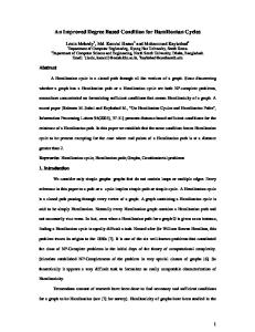
[email protected] Abstract— Profile-Based Location Caching with Fixed Local Anchor (PCFLA) Strategy helps to reduce the total location management cost by reducing the frequent access at HLR in wireless mobile network. The HLR is informed each time, whenever an MT moves from one LSTP region to another LSTP region. The old FLA and old VLR know about that by registration cancellation message from HLR. Then the old FLA and old VLR delete the MT’s profile and old FLA sends a registration cancellation acknowledgement message to HLR. These cancellation messages for each LSTP movement create load on the HLR as well as on the network. In this paper, Group Deregistration (GD) is used in PCFLA to reduce these loads by minimizing the signaling cost and location management cost. The analytical modeling and experimental results demonstrate that our proposed method reduces the overall cost than PCFLA. Keyword- call delivery, location management, location registration, Group Deregistration, ProfileBased Location Caching with Fixed Local Anchor I. INTRODUCTION Location management is an important issue in wireless mobile networks. It is concerned with the locating and finding an MT in the network coverage area. Basically, two types of standards are used in all types of wireless communications for location management of an MT such as IS-41 [1] and GSM [2]. Both IS-41 and GSM use two-level database hierarchy architecture. Fig. 1 [10] shows the basic architecture of the wireless mobile networks under this two-level database hierarchy. This architecture contains two types of databases such as Home Location Register (HLR) and Visitor Locator Registers (VLRs). The location information and permanent user profile for each MT is stored and maintained by HLR. VLRs are distributed throughout the network. VLRs store location information of each MT currently residing in the Registration Area (RA). The task of Mobile Switching Centers (MSCs) is to provide switching functions for the MTs in their associated RAs. In addition, the MSCs of different RAs are connected to a two-level hierarchy of Signaling Transfer Point (STP). This STP is comprised of a Regional STP (RSTP) and Local STPs (LSTP). An LSTP region consists of some VLRs and the RSTP region contains the LSTP regions. Wirelinks are used to connect these network elements. Two basic operations must be performed efficiently in Location management strategy: (1) location registration and (2) call delivery. The location registration is the process of informing the network about the MT’s current location information, and the call delivery means the process of determining the serving VLR and the cell location of the called MT prior to connection establishment between the caller and called MTs.
ISSN : 0975-4024
Dec 2011- Jan 2012
429
Md. Kowsar Hossain et al. / International Journal of Engineering and Technology Vol.3 (6), 2011-2012, 429-441
ch
HLR Remote A-link
Cra D-link
local A-link
RSTP
Cd LSTP
LSTP
Cv
VLR
Cla
MSC
Fig. 1. Network cost model.
As the numbers of the MTs within the network are exploding rapidly and their service requirements are also increasing day-by-day, The IS-41 standard cannot support these increasing amount of MTs. As a result, these MTs make the network congested and creates heavy load at HLR. Different types of strategies have been proposed to overcome this problem under the IS-41 [3]-[10]. Among those strategies PCFLA strategy is one of the modern existing strategies [10]. In PCFLA, user profiles are effectively utilized to determine at which sites throughout the networks user’s location information should be cached. In this approach, these site lists are prepared based on the long-term call related statistics maintained by the HLR from the callee’s user profile. These lists are used to store the callees’ location information to some of the most frequently calling VLR caches of the corresponding callees. In IS-41 standard, whenever an MT changes its Registration Area (RA), the HLR gets a location registration message from VLR associated with the new RA and updates the MT’s service profile to point to new RA and sends the service profile to that new VLR. The HLR also sends a registration cancellation message to the old VLR. The old VLR then removes the MT’s service profile and sends a cancellation acknowledgement message to the HLR. This is known as deregistration of MT. This deregistration method produce huge signaling traffic in network. The HLR is also accessed every time whenever an MT goes from one RA to another. As a result the load at HLR is increased. With increasing number of MTs and their service requirements, these may create serious bottleneck in the network. A deregistration method known as Group Deregistration is proposed in [11] to reduce the signaling traffic in the network. In this method, the HLR does not send the location cancellation message to the old VLR immediately after receiving the cancellation message to the new VLR of the MT. It keeps the information into a list for the old RA. When a location registration message comes from the old RA, the HLR sends the move-out MT’s list to the old VLR together with the location registration acknowledge message for the newly entered MT. According to [11], this strategy significantly reduces the signaling traffic and database access load without increasing the database size of the VLRs and replacing valid user registration records in the VLRs. In this paper, the Group Deregistration method is included into the PCFLA strategy. In PCFLA, a location update message is sent to HLR when an MT changes its LSTP region. After receiving a registration cancellation message from HLR, the old FLA and old VLR remove the MT’s information. The HLR then gets a cancellation acknowledgement message from old FLA. These produce signaling traffic and load on the network. We use the Group deregistration method in PCFLA to reduce the traffic and load. The rest of the paper is organized as follows. Section II gives an overview of the existing related research work. Our proposed approach is described in section III. Section IV provides the analytical modeling. In section V, Numerical results and comparison among different approaches based on some experimental results are described. Finally, a concluding remark is provided in section VI. II. EXISTING RELATED WORK A considerable amount of work has been done on location management to reduce the overall location management cost in terms of location registration cost and call delivery cost [3]-[10]. Some manage the location irrespective of all the wireless networks. The user location information obtained during the previous call to the user is reused by some others. These approaches reduce the call delivery cost. While, some others are used to manage the local handoff locally without informing the centralized HLR. In this way, the location registration cost is reduced. There are also some methods which use the MT’s calling statistics from the HLR and replicate its location information to these calling VLR cache to manage the local handoff locally instead of accessing the heavily congested HLR. As a result, the location registration and call delivery cost are reduced. Fig 2– Fig 5 shows some existing location management strategies. Table I describes the symbols used in Fig 2– Fig 5 and the
ISSN : 0975-4024
Dec 2011- Jan 2012
430
Md. Kowsar Hossain et al. / International Journal of Engineering and Technology Vol.3 (6), 2011-2012, 429-441
signaling and database access costs for the cost analysis is described in Table II. The following subsections give some descriptions of location management procedures of these strategies. TABLE I Description of symbols
Symbol () [] {}
Description Corresponding message number Cost for the particular signaling exchange Cost for accessing the particular database Exchange of the particular signaling message Acknowledgement of the signaling message
TABLE II Description of cost parameters
Parameter Cla Cd Cra Cv Cf Ch
Description Cost for sending a signaling message through the local A-link Cost for sending a signaling message through D-link Cost for sending a signaling message through the remote A-link Cost for a query or an update of the VLR Cost for a query or an update of the FLA Cost for a query or an update of the HLR
A. IS-41 Standard In basic IS-41 standard [1], each MT informs its location information to the HLR during all type of handoff procedures. When a call is initiated, the called MT’s location information is searched in the HLR. MT (1)
New VLR/MSC
[Cla+Cd+Cra]
Old VLR/MSC
HLR
(2)
[Cla+Cd+Cra]
(3)
[Cla+Cd+Cra]
{Cv}
(4)
[Cla+Cd+Cra]
(5)
[Cla+Cd+Cra]
{Ch}
{Cv}
Fig. 2. Location registration under the IS-41 standard.
The location registration procedure of this strategy can be described using the following steps (see Fig. 2). (1) An MT enters into a new RA and informs its new location to the new MSC through the nearby BTS. (2) The MSC updates its associated VLR about this newly entered MT. After that, it sends a location registration message to the HLR. (3) After receiving the location registration message, the HLR updates the MT’s record and sends back a registration acknowledgement message to the new VLR. (4) It also sends a registration cancellation message to the old VLR. (5) The old VLR removes the record of the MT immediately and sends back a cancellation acknowledgement message to the HLR. MT (1)
Calling VLR/MSC
[Cla+Cd+Cra]
HLR
(2)
[Cla+Cd+Cra]
(5)
[Cla+Cd+Cra]
Called VLR/MSC
(3)
[Cla+Cd+Cra]
(4)
[Cla+Cd+Cra]
(6) Call Setup
{Cv}
{Ch}
{Cv}
Fig. 3. Call delivery under the IS-41 standard.
ISSN : 0975-4024
Dec 2011- Jan 2012
431
Md. Kowsar Hossain et al. / International Journal of Engineering and Technology Vol.3 (6), 2011-2012, 429-441
On the other hand, the call delivery procedure under this strategy is described as follows (see Fig. 3). (1) The calling MT initiates a call and sends a signal to its serving MSC through a nearby base station. (2) The calling MSC sends a request message to the HLR for the called MT’s location information. (3) The HLR determines the called MT’s current serving MSC and sends a location request message to that MSC. (4) The MSC allocates a Temporary Local Directory Number (TLDN) [10] to the MT and sends back a reply to the HLR together with the TLDN. (5) The HLR propagates this information to the calling MSC. (6) The MSC sends a call setup request message to the called MSC through the network shown in Fig. 1.
B. PCFLA Strategy PCFLA strategy [10] is a combination of LC (Location Caching) strategy and FLA (Fixed Local Anchor) strategy. It takes the advantages of both LC strategy and FLA strategy. In PCFLA strategy, each LSTP has a FLA (Fixed Local Anchor) which is actually a specific VLR. The FLA has a table which keeps the current serving VLR for all MTs in its LSTP region. When an MT enters into a new RA then the MSC of the new RA registers the MT’s location at the FLA. The HLR then gets the information about the new FLA. The FLA may be the current serving VLR or the other VLR within that RA. However, all the user profiles are stored and manage in the current HLR in the PCS systems which contains the user information such as a user‘s location, authenticate information, and calling activity log, etc.
New VLR/MSC
MT
FLA/MSC
Old VLR/MSC
(1) (2) [2Cla] (3) [2Cla] (4) [2Cla] (5) [2Cla]
{Cv}
{Cf}
{Cv}
(a) Intra- LSTP movement MT
New VLR/MSC (1)
New FLA/MSC
HLR
Caching MSC
Old VLR/MSC
Old FLA/MSC
(2) [2Cla] ( 6.1) [Cla+Cd+Cra] (6.3) [2Cla] ( 6.2) [Cla+Cd+Cra]
( 6.4) [Cla+Cd+Cra] ( 6.5) [Cla+Cd+Cra] ( 6.6) [Cla+Cd+Cra]
(6.7) [2Cla] (6.8) [2Cla]
{Cv}
{Cf }
{Ch}
{0}
{Cf}
{Cv}
(b) Inter- LSTP movement Fig. 4. Location registration under the PCFLA strategy.
The location registration procedure under the PCFLA strategy is described in the following steps (see Fig. 4 (a)). (1) An MT sends a location update registration signal to the new MSC through the nearby BS after entering to the new RA. (2) The MSC sends a location registration message to its designated FLA in its LSTP region to check whether it has the MT’s profile. (3) If the MT has just moved into a new LSTP region then MT’s record will not be found in the FLA. In that case, go to step (6). On the other hand, if the FLA contains the MT’s record then, it updates the MT’s previous
ISSN : 0975-4024
Dec 2011- Jan 2012
432
Md. Kowsar Hossain et al. / International Journal of Engineering and Technology Vol.3 (6), 2011-2012, 429-441
record with the new one which indicates the associated new VLR. The FLA then sends a registration acknowledge message to the new MSC together with a copy of the MT’s current record. (4) After that, The FLA sends a message to the old MSC to remove the MT’s record. (5) The old MSC removes the move- out MT’s information from its associated VLR and sends an acknowledge message to the FLA to inform that the deletion is complete. (Location registration by intra-LSTP movement is complete. Do not continue to the next step). (6) If there is no MT’s record in FLA then the following steps are performed (see Fig. 4 (b)). 6.1) The MSC associated with the MT’s new FLA sends a message to the HLR for location registration. 6.2) As the MT moves to a new FLA, the HLR updates the MT’s record with that information and sends a copy of the MT’s updated profile to the new FLA. 6.3) The FLA updates its table by the MT’s record to indicate that the associated new VLR and sends a copy of the MT’s profile with a registration acknowledgment message. 6.4) All the MSCs those have location cache for the MT should be updated. For this reason, the HLR sends location cache update messages to those MSCs. 6.5) The HLR sends a message to the MT’s old FLA to cancel the registration of the MT, which then removes the MT’s record. 6.6) In response of the registration cancellation message from the HLR, the old FLA sends a registration cancellation acknowledgment message back to the HLR. 6.7) The old FLA sends a registration cancellation message to the MT’s old VLR in order to remove the MT’s obsolete record. 6.8) After removing the MT’s record, the old VLR sends a registration cancellation acknowledgment message back to the old FLA (Location registration by inter-LSTP movement is complete). Calling VLR/MSC
MT (1)
Called FLA/MSC
(2) [2Cla] or [2Cla+2Cd] (4) [2Cla]
Called VLR/MSC
(3) [2Cla]
or [2Cla+2Cd]
(5) Call setup
{Cv}
{Cf}
{Cv}
(a) When calling MSC has location cache for the called FLA MT
Calling VLR/MSC (1)
HLR
( 6.1) [Cla+Cd+Cra]
Called FLA/MSC
( 6.2) [Cla+Cd+Cra]
Called VLR/MSC
(6.3) [2Cla]
( 6.4) [Cla+Cd+Cra]
( 6.5) [Cla+Cd+Cra]
(6.6) Call setup
{Cv} (b)
{Ch}
{Cf}
{Cv}
When calling MSC does not have location cache for the called FLA Fig. 5. Call delivery under the PCFLA strategy.
The call delivery procedure under the PCFLA strategy is described as follows (see Fig. 5 (a)). (1) The calling MT initiates a call and sends a signal to its serving MSC through the nearby base station. (2) The calling MSC checks its cache for the location of the called MT’s FLA. If the location is found then it sends a location request message to the called FLA. Otherwise, go to the step (6). (3) The called FLA then forwards the location request message to the called MSC for the called MT. (4) The called MSC allocates TLDN to the MT and sends a reply back to the calling MSC together with the TLDN. (5) The calling MSC sends a message for call setup to the called MSC through the network show in Fig. 1 (Call delivery is complete. Do not continue to the next step). (6) If the calling MSC’s cache does not contain the location of the called FLA, the following occurs (see Fig. 5 (b)). 6.1) The calling MSC sends a request message to the HLR for the location of called MT.
ISSN : 0975-4024
Dec 2011- Jan 2012
433
Md. Kowsar Hossain et al. / International Journal of Engineering and Technology Vol.3 (6), 2011-2012, 429-441
6.2) The HLR sends a location request message to the called FLA. 6.3) The called FLA then forwards this message to called MSC. 6.4) The called MSC allocates TLDN to the MT and reply back to the HLR together with the TLDN. 6.5) After receiving this information, the HLR forwards it to the calling MSC. 6.6) The calling MSC send a message for call setup to the called MSC through the network shown in Fig. 1 (Call delivery is complete). C. Group Deregistration This method is used to minimize the messages exchange between HLR and VLRs. As a result, the HLR is accessed fewer times than before. The procedure of Group Deregistration strategy [11] can be described as follows. (1) When an MT moves a new RA, the HLR gets a registration message from the VLR associated with the new RA. (2) The HLR updates the MT’s service profile to indicate that it is now in new RA. The HLR does not send a registration cancellation message to the old VLR immediately; rather it keeps the identification of the MT in a list maintained for the old RA. The list is called old MT list (OML). (3) The HLR sends a registration acknowledgment message to the new VLR of the MT along with a copy of the MT’s service profile and all MTs identifications kept in the OML of the new RA, and empties this OML. (4) The new VLR associated with the new RA receives the registration acknowledgement message and takes the move-out MTs’ identifications from the message. After that, the VLR removes these MTs’ service profiles. Thus, whenever a new MT enters into a new RA, the obsolete MTs’ records of that RA are removed from the associated VLR. In that case, a new MT’s identification may be in the new RA’s OML, if the RA has performed no registrations since the MT’s last departure from the same RA. In this case, the new MT’s record in the new VLR would be deleted. To avoid this, the new MT is allocated a record in the new VLR only after the MT has registered itself at the HLR and the VLR has deleted the obsolete user records. So, the HLR contains OML for every RA. Assume, the size of an OML is K. An eager deregistration is needed if the number of entries of an OML exceeds K since the last registration. In that case, the HLR sends all MT identifications that are currently in the OML together with the identification of the MT leaving the RA most recently and empties the OML. After receiving the MT identifications from the HLR, the VLR associated with the RA deregisters the corresponding MTs.
III. PROPOSED STRATEGY In the PCFLA strategy, whenever an MT performs inter-LSTP movement the new MSC associated with the new FLA sends a location registration message to HLR. The HLR updates the MT’s profile and sends this profile to the new FLA. The HLR also sends a registration cancellation message to old FLA. The old FLA removes the MT’s record and also tells the old VLR to remove the MT’s information. The old VLA then sends a registration cancellation acknowledgement message to HLR. So, two signaling messages are exchanged between HLR and old FLA and two are exchanged between old FLA and old VLR for each LSTP movement of MT which increases the signaling traffic and creates load on HLR. To minimize these extra messages Group Deregistration method is used in PCFLA in our proposed strategy which is known as PCFLA with Group Deregistration (PCFLAGD). New VLR/MSC
MT (1)
Old VLR/MSC
FLA/MSC (2) [2Cla] (3) [2Cla]
(4) [2Cla] (5) [2Cla]
{Cv}
{Cf}
(a) Intra- LSTP
ISSN : 0975-4024
Dec 2011- Jan 2012
{Cv}
434
Md. Kowsar Hossain et al. / International Journal of Engineering and Technology Vol.3 (6), 2011-2012, 429-441
New VLR/MSC
MT (1)
New FLA/MSC
(2)
[2Cla]
HLR
Caching MSCs
(6.1)
[Cla+Cd+Cra] (6.2)
(6.3)
{Cv}
[2Cla]
[Cla+Cd+Cra]
(6.4)
[Cla+Cd+Cra]
{Cf }
{Ch}
{0}
(b) Inter- LSTP movement Fig. 6. Location registration under PCFLAGD
The location registration procedure under PCFLAGD is done using the following steps (see Fig. 6 (a)). (1) An MT sends a location update registration signal to the new MSC through the nearby BS after entering to the new RA. (2) The MSC sends a location registration message to its designated FLA in its LSTP region to check whether it has the MT’s profile. (3) If the MT has just moved into a new LSTP region then MT’s record will not be found in the FLA. In that case, go to step (6). On the other hand, if the FLA contains the MT’s record then it updates the MT’s previous record with the new one which indicates the associated new VLR. The FLA then sends a registration acknowledge message to the new MSC together with a copy of the MT’s current record. (4) After that, The FLA sends a message to the old MSC to remove the MT’s record. (5) The old MSC removes the move- out MT’s information from its associated VLR and sends an acknowledge message to the FLA to inform that the deletion is complete. (Location registration by intra-LSTP movement is complete. Do not continue to the next step). (6) If there is no MT’s record in FLA then the following steps are performed (see Fig. 6 (b)). 6.1) The MSC associated with the MT’s new FLA sends a message to the HLR for location registration. As the MT moves to a new FLA, the HLR updates the MT’s record with that information. But the HLR does not send a registration cancellation message to the old FLA immediately like PCFLA strategy; rather it keeps the identification of the MT in a list maintained for the old LSTP. The list is called old MT list (OML). The HLR also sends a copy of the MT’s updated profile to the new FLA. The HLR also sends all MTs identifications kept in the OML of the FLA’s associated LSTP, and empties this OML. 6.2) The new FLA updates its table by the MT’s record to indicate that the associated new VLR. It also deletes all the MT’s record from its table which is found from HLR 6.3) After that it sends a copy of the MT’s profile to the new VLR together with the obsolete MTs’ identifications. 6.4) All the MSCs those have location cache for the MT should be updated. For this reason, the HLR sends location cache update messages to those MSCs. (Location registration by inter-LSTP movement is complete). The call delivery procedure under the PCFLAGD is same as the PCFLA strategy. IV. ANALYTICAL MODEL To evaluate the performance of our proposed strategy and PCFLA strategy a fluid flow mobility model [12] is used. In this model, there needs some assumptions such that MTs are moving at an average speed of v in uniformly distributed direction over [0, 2π] with a view to crossing the LSTP region composed of N equal rectangular-shaped and sized RAs [10]. The following parameters used for the MTs’ movement rates analysis. : the MT’s movement rate out of an RA
: the MT’s movement rate out of an LSTP region : the MT’s movement rate to an adjacent RA within a given LSTP region
According to [13], these parameters are calculated as follows.
ISSN : 0975-4024
4v
S 4v
(1) (2)
NS
Dec 2011- Jan 2012
435
Md. Kowsar Hossain et al. / International Journal of Engineering and Technology Vol.3 (6), 2011-2012, 429-441
1
1 N
(3)
Where v is the average moving speed of an MT, S is the size of the RA, and N is the number of RAs within a LSTP region. A continuous-time Markov Chain state transition diagram is used to show an MT’s RA movement. It is shown in Fig. 7 which represents the fluid flow mobility model. Each state i(i 0) defines as the RA number of a given LSTP region where an MT can stay and state 0 means the MT stays outside of this region. The state transition ai , j 1 (i 1) represents an MT’s movement rate to an adjacent RA within a given LSTP region, and
a0,1 represents an MT’s movement rate to an RA of that region from another one. On the other hand,
bi ,0 (i 1) represents an MT’s inter-LSTP region movement rate and it is assumed that there are maximum K number of such movements. Therefore, from Fig. 7, it is obtained that
ai, j1(i 1)
and
a0,1 bi ,0
,
respectively.
a0,1
0
a1,2
1 b1,0
....
2
ak-1,k
K
b2,0
bk,0 Fig.7. State transition diagram of an MT’s RA movement
On the other hand, assuming that i is the equilibrium probability of state i, the following equations can be obtained from a continuous-time Markov Chain given in Figure 7. K
0 i
(4)
i 1 i , i0 i 1 i , 2 i K 1 iK i 1 i ,
(5) (6)
i 1
(7)
According to the law of the total probability, the sum of the probabilities of all states is 1. So, K
0 1 2 K i 1
(8)
i 0
By substituting (8) into (4), it can be obtained the equilibrium probability of state 0, 0 .So,
0 Finally, from (5), (6), (7) and (9),
i
1 2
(9)
is obtained as follows.
1 2 1 i 2 i 1 1 2
if i 0
i 1
if 1 i K 1
(10)
if i K
In this section, based on the user mobility model, we derive the location registration costs, the call delivery costs and the total location management costs of the PCFLAGD strategy. Table III shows the various parameters used for the cost analysis of PCFLAGD strategy.
ISSN : 0975-4024
Dec 2011- Jan 2012
436
Md. Kowsar Hossain et al. / International Journal of Engineering and Technology Vol.3 (6), 2011-2012, 429-441
TABLE III Parameters used for the cost analysis.
Pl Pn Po Pf Pc
Probability (caller and callee are located within the same LSTP region) Probability (new VLR is the FLA) Probability (old VLR is the FLA) Probability (callee is located in the FLA area) Probability (calling MSC has location cache for the called FLA under the PCFLAGD strategy) The MT’s CMR (call-to-mobility ratio) The number of the MSCs which have location caches for the called FLA under the PCFLAGD strategy (= the number of the most frequently calling VLRs to the specify)
q m
Table II and III describe different parameters that are used in order to calculate location management cost, signaling cost. The following notations are also used to represent the cost of each strategy [10]. UX: The average location registration cost of the X strategy for an MT staying in an LSTP region. SX: The average call delivery cost of the X strategy for an MT staying in an LSTP region. TX: The average total location management cost of the X strategy for an MT staying in an LSTP region.
U YX : the average location registration cost of the X strategy generated by movement type Y for an MT
staying in an LSTP region From Fig. 7, the average number of unique RAs that an MT visits within a given LSTP for K movements which can be represented by the following equation. K
( K ) 1 2 2 3 3 K K i i
(11)
i 1
The average location registration cost under the PCFLAGD strategy can be expressed as [10]:
U U U U
= 0 *U PCFLAGD + ( (K) -1) *U int er
PCFLAGD int er PCFLAGD int ra PCFLAGD int er
PCFLAGD
Where
and
U
int ra PCFLAGD
int ra PCFLAGD
(12)
can be expressed as follows:
pn 1 p0 M1 p0 1 pn M 2 1 pn 1 p0 M 4 = pn 1 p0 M1 p0 1 pn M 2 pn p0 M 3 1 pn 1 p0 M 4
=
(13) (14)
M x (x ε {1, 2, 3, 4}) = location registration costs for intra-LSTP movement in case of (x) given in Table
IV.
M x (x ε {1, 2, 3, 4}) = location registration costs for inter-LSTP movement under PCFLAGD strategy in case
of (x) given in Table IV. These costs can be expressed as follows (see Fig. 6(a) and 6(b)):
M 1 = M 2 = 2 2Cla Cv C f
(15)
M 4 4 2Cla 2Cv C f M 1 = 3Cla Cd Cra mCla Cd Cra 2Cf Ch M 2 = 3Cla Cd Cra mCla Cd Cra Cf Ch 22Cla Cv
(16) (17) (18)
The HLR should update m location caches for the MT throughout the networks which occurs for the interLSTP movement. In this case, the signaling cost for sending cache update messages is taken under consideration, but the cache access cost is ignored because it is relatively too small as compared to the database access cost [3]. TABLE IV Four possible cases for location registration under PCFLAGD strategy.
ISSN : 0975-4024
Case (1)
Description New VLR is the FLA, and old VLR is not the FLA.
(2)
Old VLR is the FLA, and new VLR is not the FLA.
(3)
Both new VLR and old VLR are the FLAs.
(4)
Both new VLR and old VLR are not the FLAs.
Dec 2011- Jan 2012
437
Md. Kowsar Hossain et al. / International Journal of Engineering and Technology Vol.3 (6), 2011-2012, 429-441
On the other hand, the average call delivery cost under the PCFLAGD strategy is expressed as follows [10]:
S
PCFLAGD
Where
= Pc *
cache
C
PCFLAGD
C
cache
nocache
+ (1 - Pc) * C PCFLAGD
PCFLAGD
(19)
= the call delivery costs under the PCFLAGD strategy when the calling MSC has location
cache for the called FLA. And
C
nocache PCFLAGD
= the call delivery costs when the calling MSC does not have location cache for the called
FLA. TABLE V Four possible cases for call delivery when the calling MSC has location cache for the called FLA under the PCFLAGD strategy
Case
(1) (2) (3) (4)
Description The caller and called MT are located within the same LSTP region, and the called MT is found in the FLA area. The caller and the called MT are located within the same LSTP region, and the called MT is found in the other VLR area, not the FLA area. The caller and the called MT are located in the different LSTP regions, and the called MT is found in the FLA area. The caller and the called MT are located in the different LSTP regions, and the called MT is found in the other VLR area, not the FLA area.
According to the four possible cases given in Table V, these costs are as follows (see Fig. 5(a) and Fig. 5(b)):
C
cache PCFLAGD
= p1 Pf * N1 1 Pf * N 2 1 Pl * Pf * N 3 1 Pf * N 4
(20)
where Nx (x ε {1, 2, 3, 4}) indicates the call delivery costs when the calling MSC has location cache for the called FLA under the PCFLAGD strategy in case of case (x) given in Table V. These costs can be expressed as follows (see Fig. 5(a)): N1 2 2Cla Cv C f (21)
N 2 3 2Cla 2 Cv C f
(22)
N3 2 2Cla 2Cd Cv C f
(23)
N 4 2 2Cla 2Cd 2 Cv C f 2Cla
C
nocache PCFLAGD
(24)
= P f * D 1 1 P f * D 2
(25)
Where D1 = the call delivery costs when the called MT is found in its FLA area. And D2 = the call delivery cost when called MT is found in the other VLR area. These costs are as follows (see Fig. 5(b)): (26) D 4C C C C C C 1
la
d
ra
D1 4Cla Cd Cra
2C v
v
f
h
C f Ch 2Cla
(27)
Finally, the average total cost of the PCFLAGD strategy can be expressed as
T
PCFLAGD
= U PCFLAGD + q *
S
(28)
PCFLAGD
V. NUMERICAL RESULTS AND COMPARISONS In this section, PCFLAGD strategy compared with PCFLA strategy based on signaling cost, database access cost and total cost. For analysis purpose, N is set to 55. The number of the RA’s per LSTP region is 55 [3], [4], [6]. So, we set Pn = Po = Pf = 1/55 = 0.018 and the number of the LSTPs per region is 160/7 = 23 so the value of Pl is 1/23=0.043. For simplicity we assume Pc = 0.7 and m = 5 [10]. The value of v and S is considered as 5.6 km/h and 20 km2 [12].The comparisons are shown graphically in the following subsection by taking values from Table VI and Table VII. TABLE VI Signaling costs parameter set.
Set 1 2
ISSN : 0975-4024
Cla 1 1
Cd 1 3
Dec 2011- Jan 2012
Cra 1 6
438
Md. Kowsar Hossain et al. / International Journal of Engineering and Technology Vol.3 (6), 2011-2012, 429-441
TABLE VII Database access costs parameter set.
Set 3 4
Cv 1 1
Cf 1 2
Ch 1 3
A. Signaling cost
(a) Set (1)
(b) Set (2) Fig. 8. Signaling Costs
Signaling cost of PCFLA and PCFLAGD is determined by setting the database access cost parameters, Ch, Cv, Cf and to be 0. Table VI is used to calculate signaling costs for both PCFLAGD and PCFLA. Fig. 8 shows the comparison of Signaling costs between PCFLAGD and PCFLA. B. Database access cost For calculating database access cost we assume signaling cost is zero. Table VII is used to calculate Database access cost by setting Cla, Cd, Cra to zero. As the old VLR and old FLA database are not accessed during interLSTP movement of MT in PCFLAGD but these databases are accessed in PCFLA strategy. So our proposed strategy performs better than PCFLA strategy in case of database access cost and the comparison is shown in Fig. 9.
(a) Set (3)
ISSN : 0975-4024
Dec 2011- Jan 2012
439
Md. Kowsar Hossain et al. / International Journal of Engineering and Technology Vol.3 (6), 2011-2012, 429-441
(b) Set (4) Fig. 9. Database Access Costs
C. Total cost We calculate the total cost by considering set (1) and set (3) in Fig. 10(a) and set (2) and set (4) in Fig. 10(b). In both cases, PCFLAGD shows better result than PCFLA.
(a) Set (1) and Set (3)
(b) Set (2) and Set (4) Fig. 10. Total Costs
Accoridng to [11], a small amount of storage is needed in HLR for the OML for each LSTP and the length of existing registration acknowledgement message does not increase so much to include the old mobile list. So, cosidering the above comparisons and the amount of extra storage needed in HLR it can be concluded that PCFLAGD has better performance than PCFLA strategy.
VI. CONCLUSION Location management in wireless mobile networks is a major concern in today’s world. To reduce location management cost an effective strategy called PCFLAGD is proposed in this paper. The proposed strategy uses Group Deregistration method with PCFLA strategy. It reduces the signaling messages and database access cost when an MT performs an inter-LSTP movement. As a result, the total cost is reduced in terms of location registration cost and call delivery cost regardless of the CMR. The numerical results and comparisons between
ISSN : 0975-4024
Dec 2011- Jan 2012
440
Md. Kowsar Hossain et al. / International Journal of Engineering and Technology Vol.3 (6), 2011-2012, 429-441
PCFLAGD and PCFLA show that proposed PCFLAGD strategy outperforms the PCFLA strategy irrespective of the MT’s calling and mobility pattern. REFERENCES [1]
Akyildiz, J. McNair, J. Ho, H. Uzunalioglu, and W. Wenye, “Mobility management in next-generation wireless systems,” Proc. IEEE, vol.87, no.8, pp.1347–1384, Aug. 1999. [2] M. Mouly and M.B. Pautet, “The GSM system for mobile communications,” 49 rue Louise Bruneau, Palaiseau, France, Telecom Publishing, January 1992. [3] R. Jain, Y.B. Lin, and S. Mohan, “A caching strategy to reduce network impacts of PCS,” IEEE J. Sel. Areas Commun., vol.12, no.8, pp.1434–1444, Oct. 1994. [4] J. Ho and I. Akyildiz, “Local anchor scheme for reducing signalling costs in personal communications networks,” IEEE/ACM Trans. Netw., vol.4, no.5, pp.709–725, Oct. 1996. [5] E. Bae, M. Chung, and D. Sung, “Performance analysis of fixed local anchor scheme for supporting UPT services in wireline networks,” Comput. Commun., vol.23, pp.1763–1776, 2000. [6] R. Jain and Y.B. Lin, “An auxiliary user location strategy employing forwarding pointers to reduce network impacts of PCS,” ACMBaltzer J. Wireless Networks, vol.1, no.2, pp.197–210, July 1995. [7] G. Varsamopoulos and S. Gupta, “Dynamically adapting registration areas to user mobility and call patterns for efficient location management in PCS networks,” IEEE/ACM Trans. Netw., vol.12, no.5,pp.837–850, Oct. 2004. [8] W. Ma and Y. Fang, “A pointer forwarding based local anchoring (POFLA) scheme for wireless networks,” IEEE Trans. Veh. Technol., vol.54, no.3, pp.1135–1146, May 2005. [9] J. Li and Y. Pan, “A dynamic HLR location management scheme for PCS networks,” Proc. INFOCOM ’2004, vol.1, pp.266–276, March 2004. [10] K. Kong. “Performance analysis of profile-based location caching with fixed local anchor for next-generation wireless networks”. IEICE transactions on communications, E91-B(11):3595– 3607, November 2008. [11] Zuji Mao,, Christos Douligeris, "Group Deregistration Strategy for PCS Networks," IEEE COMMUNICATIONS LETTERS, VOL. 6, NO. 4, APRIL 2002. [12] F. Baumann and I. Niemegeers. “An evaluation of location management procedures”. In Proceedings of the Third Annual International Conference on Universal Personal Communications, USA, pp. 359–364, September 1994. [13] K. Kong, M. Song, K. Park, and C. Hwang. “A comparative analysis on the signaling load of Mobile IPv6 and Hierarchical Mobile IPv6: Analytical approach”. IEICE Transactions on Information and Systems, E89-D(1):139–149, Japan, January 2006.
ISSN : 0975-4024
Dec 2011- Jan 2012
441