Background
Improved control scheme
An Improved Control Law Using HVDC Systems for Frequency Control Jing Dai1 1 Department 2 Laboratoire
Gilney Damm2
of Energy, SUPELEC, Gif-sur-Yvette, France
IBISC, Université d’Evry-Val d’Essonne, Evry, France
2013 EPRI HVDC & FACTS Conference San Francisco, CA August 28, 2013
Conclusions
Background
Improved control scheme
Outline
1
Background
2
Improved DC-voltage-based control scheme for primary frequency control
3
Conclusions
Conclusions
Background
Improved control scheme
Conclusions
Primary frequency control
Frequency control: limit frequency variations and restore balance between generation and load demand. Primary frequency control: Time scale: a few seconds. Based on local frequency measurements. Adjustment of power injections (mainly by generators). Primary reserves: power margins deployable within a few seconds.
Larger synchronous area: More generators participating in primary frequency control. Lower costs of reserves per MW. Motivation to extend synchronous areas at a continental scale.
Background
Improved control scheme
Conclusions
Multi-terminal HVDC system
DC grid P1dc
PNdc
P2dc
AC area 1
AC area N AC area 2
Generally, Pidc are supposed to track pre-determined power settings. Primary frequency control is independent from one area to another. Is it possible to share primary reserves among these AC areas as if they were connected by a large AC grid?
Background
Improved control scheme
Conclusions
Previous work 1: a simple solution Auxiliary Frequency Controller
Change the exchanged power (P dc ) based on the frequency difference between both areas, so that ∆fA = ∆fB . Generalized to a multi-terminal HVDC system in a previous paper [Dai, Phulpin, Sarlette & Ernst 2010]. Problems with time-delays due to dependency on remote information.
Background
Improved control scheme
Conclusions
Previous work 2: DC-voltage-based control scheme [Dai, Phulpin, Sarlette & Ernst 2011] Control objective: to share primary reserves among non-synchronous areas. Control variables: V1dc , . . . , VNdc . Subcontroller for area i controls Vidc such that ∆Vidc = α∆fi where α: controller gain; ∆Vidc : Variation of Vidc with respect to the steady-state value; ∆fi : Frequency deviation from 50 Hz.
Background
Improved control scheme
Conclusions
Principle of the DC-voltage-based control scheme
∆Vidc = α∆fi 1
A positive power imbalance (generation surplus) in area i: fi ↑;
2
The control law: Vidc ↑;
3
The DC load flow equation Pidc = Pidc ↑;
4
PN
k =1
Vidc (Vidc − Vkdc ) : Rik
The positive power imbalance within area i is mitigated: fi ↓.
Background
Improved control scheme
Conclusions
Features of the DC-voltage-based control scheme
Decentralized: each area acts only based on local information. The HVDC converters functioning in non-conventional mode: all the converters control the DC voltage. Following a disturbance, all the frequency deviations (fi ) get close to each other, but they remain different in the steady state. This lead to a smaller degree of primary reserve sharing, than the case of identical (fi ) as with the control scheme acting on Pidc .
Background
Improved control scheme
Outline
1
Background
2
Improved DC-voltage-based control scheme for primary frequency control
3
Conclusions
Conclusions
Background
Improved control scheme
Conclusions
Improved DC-voltage-based control scheme for primary frequency control Original DC-voltage-based control scheme: ∆Vidc = α∆fi Improved version: ∆Vidc = α∆fi + β
Z ∆fi dt − γ
Z X N
∆Vkdc dt
k =1
Role of β term: to eliminate the steady-state error between ∆fi . Role of γ: to prevent ∆Vidc from continually drifting. In fact, if γ = 0, then, ∆Vidc would keep changing as long as ∆fi 6= 0.
Background
Improved control scheme
Conclusions
System dynamics for each area Equation of motion: 2πJi
Pmi (t) − Pli (t) − Pidc (t) dfi (t) = − 2πDgi (fi (t) − fnom,i ) dt 2πfi
Primary frequency control: Tsmi
P max fi (t) − fnom,i dPmi (t) o = Pmi − Pmi (t) − mi dt σi fnom,i
HVDC converter control scheme: ∆Vidc (t)
Z = α∆fi (t) + β
∆fi (t)dt − γ
Z X N k =1
∆Vkdc (t)dt
Background
Improved control scheme
Conclusions
Stability study
Linearisation assumptions: 2πJi
Pmi (t) − Pli (t) − Pidc (t) dfi (t) = − 2πDgi (fi (t) − fnom,i ) dt 2πfnom,i
Results: following a disturbance, the closed-loop system is stable and converges to a unique equilibrium where the frequency deviations of all the AC areas are identical. Proof sketch: first find the state-space model of the closed-loop system; then prove by contradiction that the eigenvalues of the state matrix must have negative real part.
Background
Improved control scheme
Conclusions
Empirical study
An MT-HVDC system with 5 areas: Each area is modelled by an aggregated generator and an aggregated load. A model: without simplifying assumptions made in the theoretical study. Power imbalance: a step increase by 5% in the load demand of area 2 at t = 2s.
Area 1 Area 5
Converter
Area 2 Converter
Converter Area 3
Converter
Converter Area 4
Background
Improved control scheme
Conclusions
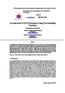
Simulation result: fi fi under the improved law (β 6= 0, γ 6= 0).
50
50
49.99
49.99
frequency (Hz)
frequency (Hz)
fi under the original control law (β = γ = 0).
49.98 49.97 1 2 3 4 5
49.96 49.95 49.94 49.93 0
5
10
15 time (s)
20
25
49.98 1 2 3 4 5
49.97 49.96 49.95 49.94
30
49.93 0
5
10
15 time (s)
Conclusion: the improved control law eliminates the steady-state error between fi .
20
25
30
Background
Improved control scheme
Conclusions
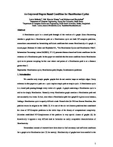
Simulation result: Vidc Vidc under the improved control law.
Vidc when γ = 0.
100 V5
99.8
V5
99.8
V3
99.6
V3
99.6
V4
99.4
V4
99.2
V2
99.4
V2
99
V1
99.2
V1
99 0
5
10
15 time (s)
V (kV)
V (kV)
100
98.8
20
25
30
98.6 0
5
10
15 time (s)
20
25
Conclusion: the γ term is able to prevent Vidc from continually drifting.
30
Background
Improved control scheme
Conclusions
Practical implementation The γ term necessitates communication between the HVDC terminal. We update the γ term only every 500 ms. Little impact is observed on fi . The curves of Vidc become serrated. Vidc when the γ term is updated continuously.
99.8
V3
99.6
V4
99.4
V2
99.2
V1
99 0
100
V5
5
10
15 time (s)
V5
V (kV)
V (kV)
100
Vidc when the γ term is updated only every 500 ms.
20
25
30
99.8
V3
99.6
V4
99.4
V2
99.2
V1
99 0
5
10
15 time (s)
20
25
30
Background
Improved control scheme
Outline
1
Background
2
Improved DC-voltage-based control scheme for primary frequency control
3
Conclusions
Conclusions
Background
Improved control scheme
Conclusions
A improved control scheme acting on HVDC converters’ DC voltage for coordinating primary frequency control efforts among the AC areas. Theoretical results: proof stability of the closed-loop linearised system. Simulation results: the frequency deviation of all the AC areas are identical in steady state.
Conclusions