An Adaptive Fault-Tolerant Memory System for FPGA-based Architectures in the Space Environment Dan Fay, Alex Shye, Sayantan Bhattacharya, and Daniel A. Connors University of Colorado {faydr, shye, bhattacs, dconnors}@colorado.edu
1
Abstract
Electronic systems at high altitudes above the Earth are subject to ionizing radiation that adversely affects circuit operation in various ways. For these reasons, high-density, SRAM-based FPGA (Field Programmable Gate array) systems have historically been unsuitable for use in space due to their higher susceptibility to radiation-induced Soft Error Upsets (SEUs). However, there are a number of reasons for pursuing the deployment of adaptive FPGA-based designs in spacecraft systems and satellites. Frequently mission requirements change and FPGA systems are a mutable low-cost electronic fabric capable of adjusting to new design constraints after a system is initially released. Moreover, an adaptive FPGA design can attenuate the amount of fault tolerance in the system to the specific levels of radiation and the amount of available power, resources, and performance. Previously, the Triple3 Redundant Space Systems (T3RSS) approach demonstrated the use of partial reconfiguration of FPGA logic to ensure fault tolerance in FPGA-based space systems. This paper explores the issues germane to developing a reliable, high-performance memory system for FPGA architectures that seamlessly withstands both radiation-induced SEUs and permanent failures in space system hardware components.
bits to change and logic outputs to evaluate incorrectly. Additionally, radiation can cause permanent damage to silicon devices over time, ultimately rendering all or part of the device unusable. Some FPGAs are more susceptible to these upsets than others: FPGAs which hold their programming information in either antifuses or EEPROMs are less susceptible to upsets in their configuration memory than are SRAM-based FPGAs [1]. As a result, SRAM-based FPGAs have historically been less desirable for use in critical spacecraft electronics. SRAM-based FPGAs, however are worth considering as an alternative to antifuse-programmed FPGAs. SRAM-based FPGAs are based on the newest commercially available manufacturing processes and therefore have superior performance, density, and power/heat dissipation advantage over other FPGA technologies. The newest SRAM-based FPGA devices provide a runtime tool for detecting and eliminating these configuration faults: partial reconfiguration. Partial reconfiguration allows part of the FPGA to be reprogrammed while the rest of the FPGA continues to run uninterrupted. Partial reconfiguration detects errors within the configuration memory and reprograms the faulty configuration to its original operation through a technique known as scrubbing.
2.2
2 2.1
Introduction Using FPGAs in Space
FPGA (Field Programmable Gate Array) devices, like other electronics at high altitudes, are subject to ionizing radiation that adversely affect electronics in various ways. Radiation can cause both short-term and permanent device failures. In the short term, they can cause transient upsets in circuits known as Soft Error Upsets (SEUs). SEUs occur when an energetic particle (typically a proton, neutron, or heavy ion) collides with atoms in the silicon lattice and leaves electric charges in its wake. SEUs can cause state
Steve Wichmann ReDefine Technologies {steve}@redefine.com
The Need For Adaptability
An FPGA-based space system can rapidly adapt to changing mission conditions and requirements. With the FPGA capable of reforming hardware for new functionality, FPGAs can perform systematic relocation in the event the system suffers from permanent, hard failures in electronic circuitry. However, the more likely scenario is for the system to adaptively increase and decrease the fault tolerance as needed, since fault tolerance schemes incur significant penalties in terms of logic utilization, memory utilization, and power consumption/heat dissipation. Adaptable fault tolerance is useful for attenuating to varying radiation conditions. If, for example, the spacecraft is going to be experiencing high levels of radiation (such as solar storms,
Noise Rem.
Telem.
Attitude Control
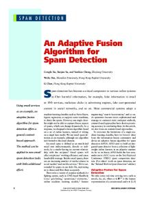
more memories, and complete failure of one or more memories. The symmetric design makes it straightforward for the system to adapt to any of the aforementioned failure modes. If a device should fail, its functionality can be seamlessly moved to another FPGA-memory pair. A point-to-point network allows all of the FPGAs to directly access the other FPGAs and their attached memory. The T3RSS architecture allows a given FPGA to use other FPGAs’ memory as a remote backup to preserve important program data in the event of device failure, or merely to provide an added level of protection against SEUs. A point-to-point FPGA interconnection topology is more reliable than using a shared bus: if one of the FPGAs fails, it can only take down the links connected to itself. Additionally, point-to-point links provide lower latency and more deterministic operation than does having to use a shared bus, helping to ensure proper real-time performance.
Legend FPGA
Noise Removal
Memory
Attitude Control
Logic Region
Non−functional
FPGA−FPGA Interconnect
Telemetry
Memory Region
Telem.
Memory Region With Backup Data
Attitude Control
m
Figure 1. The proposed T3RSS system with attached memory.
3.2 passing through the Van Allen radiation belts, or passing over the South Atlantic Anomaly) it should be able to remove non-essential functionality (such as off-line image or signal processing) and use the available logic to increase the fault tolerance of more-critical electronics (such as attitude control or telemetry).
3
To provide logic-level reliability, T3RSS provides several different approaches, each one designed to deal with a particular source of faults. Since the low-level logic itself is susceptible to SEUs, all of the logic is triplicated using the proven Triple Modular Redundancy (TMR) technique [8]. This technique triplicates all of the logic. If an error occurs in one of the copies of the logic, a voter scheme chooses the correct result. The T3RSS design also triplicates the nonvolatile storage and access to external peripherals. T3RSS deals with errors in the configuration memory and hard errors in parts of the FPGA using partial reconfiguration, which allows for changing parts of the FPGA while running. T3RSS uses partial reconfiguration for relocating functionality around hard failures within the FPGA fabric as well as to scrub out errors in the configuration memory. By reading in the current configuration, checking it for errors, and reconfiguring the FPGA area with a clean configuration, errors in the FPGA’s configuration can be scrubbed out without interrupting running functionality.
Improving the Reliability of SRAM-based FPGAs
In order for SRAM-based FPGAs to be a viable alternative to rad-hard components in space, it is essential to improve their reliability. Our approach, known as Triple3 Redundant Spacecraft Systems (T3RSS) [3], applies the goals of the JPL REE project [4], that is, making a high performance, reliable spacecraft system out of low-cost Commercial Off-The-Shelf (COTS) parts, to reconfigurable systems for small satellites and spacecraft.
3.1
Logic-level Fault Tolerance
System-Level Design
4
The T3RSS system allows for mission survivability through failure of entire devices by providing complete device-level redundancy. Figure 1 shows the proposed T3RSS board. This board will contain multiple FPGAs, with each FPGA having its own local, directly-attached memory. Each FPGA is directly connected to each of the other FPGAs using a dedicated point-to-point links. Figure 1 also illustrates the possible failure modes for the T3RSS FPGA system: partial failure of one or more FPGAs, complete failure of one or more FPGAs, partial failure of one or
Memory System Design
A reliable, distributed multi-FPGA-based system needs a reliable, distributed memory system to go with it. While there are many different memory systems that provide varying degrees of fault tolerance, a distributed, multi-FPGA system specifically needs a memory system and interconnection network that has no single point of possible failure and keeps up-to-date copies of the memory directly accessible by other FPGAs. These additional copies are necessary in the event the local FPGA’s memory becomes corrupted. 2
Memory Technology SDRAM (PC133) DDR SDRAM (DDR266) DDR2 SDRAM (PC5300)
B/W (GB/s) 1.0 (2.0) 2.1 (4.2) 5.3 (10.6)
I/O PCI32 [14] PCI-X [16] x4 PCI-E [15] RapidIO [17] [18] HyperTransport [12]
B/W (GB/s) 0.264 1.0 2.0† 1.0 1.6†
Cost (LUTs) 506 1074 10550 7000†††† 4404
I/O Count 55 94 4†† 20††† 42
Machine SRC MAP Processor [9] Maxwell SCS750 [7]
Mem. (GB/s) 11.2 0.768
FPGA Xilinx XC2VP30 [19] Xilinx XC4VLX160 [20]
Size (slices) 30,816 152,064
Num. I/Os 644 960
Num. MGTs 8 0
†
Full duplex. Actual bandwidth in either direction is half of the stated figure. Number of high-speed Multi Gigabit Transceivers (MGTs) required. ††† Number of Low Voltage Differential Signaling (LVDS) pin pairs required. †††† Includes size of Physical Layer (PHY) and Link/Transport Layer. ††
Table 1. Comparison matrix of the bandwidths of current I/O and memory technologies along with the memory bandwidths available to popular aerospace computers as well as the resources available on two representative Xilinx FPGAs.
4.1 High-level System Architecture
memory bandwidth as possible. Since the off-chip connections are slower (both by having less bandwidth and experiencing a higher latency) than the on-chip connections, large amounts of memory traffic to the fault-tolerant memory system can seriously impact system performance and prevent the application from taking full advantage of the local memory’s bandwidth. Implementing higher bandwidth links is one option, however there is ultimately a limit to how fast the interFPGA links can be. To increase the link bandwidth, one can either make the connections wider, which consumes more FPGA I/O pins, or increase the clock speed of the interFPGA link. Both of these have limits caused by limited FPGA resources. Table 1 compares the I/O and logic resource requirements of several different I/O technologies: standard PCI, PCI-X, PCI Express, RapidIO, and HyperTransport. PCI definitely does not have enough bandwidth; while the other technologies may be able to provide sufficient bandwidth, they are impractical to implement on the FPGA: PCI-X consumes too many I/O pins, and PCI Express, RapidIO, and HyperTransport consume too many logic resources (particularly when one considers that applying TMR to logic increases its size by roughly 3.2x [10]). As a result, it is necessary to investigate different bandwidth reducing strategies such as distributed error checking, posted writes, caching, and shadow (background) fault detection and correction that minimize the amount of off-chip bandwidth generated. In addition, it will be necessary to investigate the best way to preserve program state, including deciding what parts of a program actually need to be placed in fault-protected memory.
Providing data integrity when one or more FPGAs (or their memory) fails requires redundant information to be stored on the other FPGAs’ memories. As a result, the memory system should distribute changed data to the other FPGAs’ memories. Additionally, such a memory system should also be able to periodically compare the local data against the extra data on the other FPGAs to ensure correctness of the local copy. Figure 1 shows how the distributed memory system keeps copies of the data off-chip. Keeping these off-FPGA remote copies up to date requires potentially large amounts of off-chip interconnect bandwidth. Table 1 shows the bandwidths of different memory technologies. The three SDRAM configurations assume the commonly-used case of a 64-bit (and 128-bit) wide memory channel. Additional memory bandwidth is possible at the cost of using more FPGA I/Os and more complicated circuit boards. The last two rows show the memory bandwidth available to two popular aerospace computers. The first one, the SRC MAP [9] processor, is an embedded reconfigurable computer that uses Xilinx FPGAs to implement high-performance algorithms such as synthetic aperture radar, and automatic target recognition. The Maxwell SCS750 [7] is a space-qualified computer that uses three IBM PowerPC 750 microprocessors running in lockstep. The lower-right hand corner of Table 1 provides two representative FPGAs to illustrate the large amount of FPGA resources these I/O standards require. The fault tolerant distributed memory subsystem should be able to protect the memory system at as close to full 3
4.2
Benchmark bisort fir mm treeadd tsp wave dag fact
Different Approaches to Implementing Fault Tolerance
There are a variety of ways to improve the reliability of a memory system. Basic single bit detection without correction can be accomplished using parity checking. More sophisticated error detection uses checksumming techniques such as CRCs or MD5 signatures. When error correction is desired, different error-correcting codes (ECC) such as Hamming or Reed-Solomon codes can correct for one or more bit errors. Another way to implement a fault tolerant memory subsystem is to make multiple copies of the data. These techniques are orthogonal and can be used together. One way is to implement the memory as a RAID array, which servers using the Chipkill [5] technology as well as the Compaq Alpha 21364 [2] employ to improve fault tolerance over ECC-protected memory alone. RAID, short for Redundant Array of Independent Disks, can implement redundancy by distributing a piece of data across multiple disks (or this case, FPGA memories) in such a way that any one (or two, in the case of RAID level 6) disks (or memories) can fail without corrupting the stored data. These fault tolerance schemes can be used with FPGA-external memory or with the FPGA’s internal Block RAM (BRAM).
4.3
Function Sorting and merging bitonic sequences Finite Impulse Response filter Floating-point matrix multiply Adds values to a tree data structure Traveling-salesman problem Wavefront computation Directed Acyclic Graph Factorial calculation
Table 2. A list of the benchmarks studied. • Silent Data Corruption (SDC): A transient fault which goes undetected and propagates to corrupt program output is considered a SDC. Note that these errors are not always serious; a single bit flip in a digital image, for example, would appear merely as a tiny amount of noise. • Detected Unrecoverable Error (DUE): A transient fault which is detected without possibility of recovery is considered a DUE. Such an error can either cause obviously incorrect execution or force a processor or FPGA reset.
5
Adaptable Fault Tolerance
Experimental Methodology
In order to investigate how best to design an adaptive fault tolerant system, we studied the fault vulnerability and memory traffic of the benchmarks shown in Table 2.
Different applications have different reliability requirements: some applications must function without errors for months or years on end, while other applications can safely suffer periodic faults. The memory system should take these varying fault tolerance needs into account, as additional fault protection consumes valuable hardware resources that could be used for additional functionality and/or adds additional cost to the mission. Moreover, the actual vulnerability of an application to faults can vary, not only between applications but also between different parts of the program. Output data for control systems would likely need full protection; however, temporary variables, such as those on the stack, may not need as much protection. Similarly, program data or read-only variables might not need distributed, multi-FPGA protection, as they can be reloaded from nonvolatile storage if found to be corrupt. The effect that a fault has on program execution can be classified by its effect on program execution into the following categories [11]:
5.1 Fault Injection Application vulnerability was investigated by simulating SEUs in processor registers and in memory via four fault injection campaigns. The fault injection infrastructure uses the Intel Pin dynamic binary instrumentation tool [6] to study the effect of injecting faults into the source and destination registers of instructions, the BSS segment, the DATA segment, and the STACK segment. Each fault injection campaign runs each benchmark one thousand times. In each run, the fault injector uses an instruction profile and a dynamic instruction count to pick a random static instruction. Pin then proceeds to instrument the instruction. When the program reaches the corresponding dynamic count, the instrumentation code flips a random bit in a register or one of the three memory regions. The result of each fault injection run is placed into 5 categories:
• Benign Fault: A transient fault which does not propagate to affect the correctness of an application is considered a benign fault. A benign fault can occur for a number of reasons. Examples include a fault to unused data or a fault to dead (unreachable) code.
• Correct. The fault is benign and the program continues to completion and exits with a valid return code and valid output data. 4
Test
MicroBlaze
MicroBlaze
Test
UART
OPB−OPB Bridge
Shared BRAM Cntlr.
BRAM
MicroBlaze
Shared BRAM Cntlr.
OPB Mon.
0 1 0 1 0 1 0 1 0 1 0 1 0 1 0 1 0 1 0 1 0 1 0 1 0 1 0 1 0 1 0 1 0 1 0 1 0 1 0 1 0 1 0 1 0 1 0 1 0 1 0 1 0 1 0 1 0 1 0 1 0 1 0 1 0 1 0 1 0 1 0 1 0 1 0 1 0 1 0 1 0 1 0 1 0 1 0 1 0 1 0 1 0 1 0 1 0 1 0 1 0 1 0 1 0 1 0 1 0 1
Main BRAM Cntlr.
BRAM
Monitor
Timer
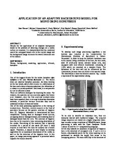
monitor. The other side of the OPB-OPB monitor bridge attaches to the Secondary OPB, to which the MicroBlaze’s main memory and its UART interface. The monitor system consists of its own MicroBlaze processor, which has its own Tightly-Coupled Memory for its code and data. Its OPB attached to the OPB monitor, a Programmable Interval Timer (PIT), and a UART. The OPB monitor is a custom block used to monitor and log the traffic information provided by the OPB-OPB monitor bridge. Before starting a program, the monitor MicroBlaze programs this part with base and high address ranges. The OPB monitor then counts every access within that address range. Each MicroBlaze also has access to a block of shared memory. This block of memory is used to implement communication between the monitor MicroBlaze and the executor MicroBlaze. Upon configuring the FPGA with the test pattern, the executor system’s processor spins on a variable in the shared memory. This holds the processor until the monitor processor is completely set up and able to begin collecting samples. Once the monitor processor is ready, it sets the shared variable, telling the executor system to begin program execution. At every PIT interrupt, the monitor system records the number of memory accesses that occurred in that interval. At every interrupt, the monitor system checks another shared variable in the shared memory that the executor system sets when it completes the program. The setting of this variable tells the monitor system to stop sampling and to prepare for uploading the collected data.
Test System
Main BRAM Cntlr.
BRAM
BRAM
Monitor System
UART
UART
Legend BRAM Block
OPB Peripheral
Bus Connection
OPB Bus
MicroBlaze Processor
Figure 2. A block diagram of the memory traffic analyzer.
• Failed. The program performs an illegal operation which immediately halts execution (e.g. bus error, segmentation violation) resulting in a DUE. • Abort. The program exits with an invalid return code. In this case, the application itself has detected an error and aborts execution resulting in a DUE. • Timeout. The fault causes the program to hang indefinitely. If the system has a timeout mechanism, this case can be considered a DUE.
6
• Incorrect. The program continues to completion, exits with a valid return code, but the resulting data is incorrect. This results in an SDC which is the worst possible outcome.
5.2
6.1
Experimental Results Application Vulnerability
There are major differences in the vulnerability profiles of various applications. Figure 3 shows the vulnerability of a set of selected applications divided into register faults and three memory segments: DATA, BSS, and STACK. All of the applications show significant vulnerability to faults injected into the register. Register vulnerability is high since data stored in registers is used frequently and involved in multiple computations. The memory fault injection selects random locations in memory regardless of usage, and has a overall lower vulnerability. However, the experiment highlights that the memory vulnerability is different for various sections and uses of memory. Generally, BSS segment data errors do no propagate to faults, except in the cases of large array structures such as matrix multiply (mm). STACK memory for selected applications have higher vulnerability, while the DATA memory section has almost uniform rates of natural protection against errors. These results motivate the use of an adaptive memory system that can be customized to the native characteristics of a diverse workload
Memory Access Patterns
To examine the memory access patterns, an FPGA-based test apparatus was implemented on a Xilinx Virtex-II Probased [19] Digilent XUPV2P-based board [21]. Figure 2 shows a block diagram of the test setup as implemented on the FPGA. Implemented on the board are two separate MicroBlaze [13]-based systems: the test system and the monitor system. The test system runs the benchmark under test while the monitor system observes the behavior of the test system. The test system consists of one (or two) MicroBlaze microprocessors responsible for executing the test program(s). The MicroBlaze interfaces with the Main OPB, which is attached to the OPB-OPB monitor bridge. The OPB-OPB monitor bridge provides snoop information to the OPB 5
Figure 3. Fault vulnerability of different applications.
BRAM Read Traffic across Different Benchmarks
BRAM Read Traffic in FIR with different Microarchitectural Setups 1500 bitonic
fir
BRAM read in each interval (linear)
BRAM Reads in each interval (linear)
1050 treadd dag
1000
tsp mm 950
fir wave fact
900
850
800
fir with 4K icache fir with 4K dcache fir with 4K dcache & 4K icache fir with second "interfering" application running
1000
500
0 0
2500
5000
7500
10000
12500
15000
17500
0
2500
5000
Time Interval
10000
12500
15000
17500
Time Interval
BRAM Write Traffic across Different Benchmarks
BRAM write Traffic in FIR with different Microarchitectural Setups
150
150 bitonic
BRAM write in each interval (linear)
BRAM writes in each interval (linear)
7500
treadd 125
dag tsp mm
100
fir wave
75
fact 50
25
0
fir fir with 4K icache fir with 4K dcache fir with 4K dcache & 4K icache fir with second "interfering" prcessor
100
50
0 0
2500
5000
7500
10000
12500
15000
17500
0
2500
5000
7500
10000
12500
15000
17500
Time Interval
Time Interval
Figure 4. Total BRAM traffic (reads and writes) by benchmark.
Figure 6. Microarchitectural features and their effects on memory traffic.
6
100
Rd (Max) Rd (Mean) W r (Max) W r (Mean)
10 1
DATA
BSS
STACK
100
Rd (Max) Rd (Mean) Wr (Max) Wr (Mean)
10 1
1000
100
Rd (Max) Rd (Mean)
10
W r (Max) W r (Mean)
1 0.1
STACK
DATA
CODE
BSS
dag
100000
10000
10000
0.1 0.01
10
Rd (Max) Rd (Mean) W r (Max) W r (Mean)
1 0.1 0.01 0
CODE
Memory Segment
DATA
BSS
STACK
100000
10000
10000
100
Rd (Max) Rd (Mean) W r (Max) W r (Mean)
10 1
CODE
100
Rd (Max) Rd (Mean) W r (Max)
10 1
W r (Mean)
0.1 0.01 0
BSS
STACK
Memory Segment
Memory Segment
STACK
1000
DATA
CODE
BSS
wave
100000
0.01
0 STACK
DATA
Memory Segment
0.1
0
0
Memory Acceses
1
Memory Accesses
Rd (Max) Rd (Mean) W r (Max) W r (Mean)
10
CODE
1000
100
100
STACK
tsp
1000
1000
1
Memory Segment
Memory Segment
mm
Rd (Max) Rd (Mean) W r (Max) W r (Mean)
10
0.01
0
BSS
100
0.1
0.01
DATA
100000
BSS
10000
0.01
CODE
Memory Segment
DATA
10000 1000
0.1
0.01
100000
Memory Accesses
1000
bitonic
100000
Memory Acceses
10000
1000
Memory Accesses
10000
0.1
Memory Acceses
fact
treadd 100000
Memory Accesses
Memory Acceses
fir 100000
CODE
DATA
BSS
CODE
Memory Segment
Figure 5. BRAM traffic by program section. Figure 6 show the effects on overall memory read and write traffic after adding a 4KB instruction cache (I-cache) to the MicroBlaze. The addition of this cache was extremely effective in reducing read BRAM traffic, however, it also had the effect of significantly increasing write traffic. Since the I-cache allows the MicroBlaze processor to execute more instructions per cycle, the system does not need to go out over the OPB to fetch every instruction. As a result, the fir application executes significantly faster, and thus produce new data requests at a higher rate. The addition of a D-cache is also shown and also clearly increases the throughput of the data processed by the fir application. The tradeoff is an increase in the amount of memory accesses, as the write-through D-cache has to constantly update the main memory with the increased load of the data.
of applications.
6.2
Memory Traffic Analysis
Figure 4 shows the overall memory traffic for the system. There exists a large variability in the read and write traffic between applications, and within each benchmark over time. The rapid change in application memory traffic, both over long periods as well as over short intervals, stresses the difficulty in providing low latency memory accesses and fault tolerance through redundancy. During these time periods, a memory system may not meet real-time deadlines if the system is trying ensure fault tolerance by triplicating all memory reads and writes. Figure 5 shows the memory traffic for specific regions of memory: the STACK segment, the BSS segment, the CODE segment, and the DATA segment. The STACK segment experiences significant memory read and write traffic, more so than the DATA segment. Since the stack holds mainly temporary variables and procedure call data, these results suggest that backing up only the DATA segment data will allow the memory system to achieve high performance without undue off-chip memory traffic. None of the applications experience significant BSS read traffic. The CODE segment reads make up the majority of the total BRAM reads. This suggests that storing the instructions separately either in a cache or in a tightly-coupled memory can significantly reduce memory read traffic.
The overall effect of adding both an I-Cache as well as a D-cache to the system clearly increases the throughput of the data generated at reduced memory accesses as shown in Figure 6. In short, these results show that design tradeoffs such as I-cache and D-cache components (as well as other components effecting the memory access rate), must not only be considered for performance but their impact in providing fault tolerance in a memory system design. Figure 6 also shows the decrease in application performance (25% in the case of reads) due to the addition of an interfering program running on a third MicroBlaze processor. The reduction in the number of memory accesses by the main process in the same interval of time clearly demonstrates 7
the bus contention between the two application processes.
7
[8] N. Rollins, M. J. Wirthlin, M. Caffrey, and P. Graham. Evaluating tmr techniques in the presence of single event upsets. In Proceedings of Military and Aerospace Applications of Programmable Devices and Technologies Conference, September 2003. [9] Map processor, 2006. Web site: http://srccomputers.com/Product Sheets/SRC MAP 69226BD.pdf. [10] Tmrtool product information brief. Web site: http://www.xilinx.com/esp/mil aero/collateral/tmrtool sellsheet wr.pdf, 2006. [11] C. Weaver, J. Emer, S. S. Mukherjee, and S. K. Reinhardt. Techniques to reduce the soft error rate of a highperformance microprocessor. In Proceedings of the 31st Annual International Symposium on Computer Architecture (ISCA), 2004. [12] Hypertransport single-ended slave, October 2003. Web site: http://www.xilinx.com/systemio/htses/hypertransport ds.pdf. [13] Microblaze processor reference guide. Web site: http://www.xilinx.com/ise/embedded/mb ref guide.pdf, June 2006. [14] Pci 64/32 interface v3 and v4. Web site: July http://www.xilinx.com/partinfo/pci/pci ds207.pdf, 2006. [15] Pci express endpoint cores v3.3. Web site: http://www.xilinx.com/bvdocs/ipcenter/data sheet/ pci exp ep ds506.pdf, September 2006. [16] Pci-x interface v5 and v6. Web site: http://www.xilinx.com/pci/docs/pcix 6466/pcix ds208.pdf, July 2006. [17] Rapidio logical (i/o) and transport layer interface v3.1. Web site: http://www.xilinx.com/ipcenter/catalog/logicore/docs/ rio log io ds.pdf, July 200. [18] Serial rapidio physical layer core v3.1. Web site: http://www.xilinx.com/bvdocs/ipcenter/data sheet/ srio phy ds.pdf, July 2006. [19] Virtex-ii pro and virtex-ii pro x platform fpgas: Complete data sheet. Web site: http://direct.xilinx.com/bvdocs/publications/ds083.pdf, October 2005. [20] Xilinx ds112 virtex-4 family overview, data sheet. Web site: http://direct.xilinx.com/bvdocs/publications/ds112.pdf, January 2007. [21] Xilinx university program virtex-ii pro development system. Web site: http://digilentinc.com/Data/Products/XUPV2P/ XUPV2P User Guide.pdf, March 2005.
Conclusion
We have presented the T3RSS space hardware system, and motivated the need for a memory system that can provide adaptive distributed fault tolerance by storing data on the memory of multiple FPGAs. Such a system cannot blindly access the other FPGAs’ memories on every memory access, however, or memory performance will be adversely affected. Therefore, it is necessary to employ various techniques to minimize the amount of off-chip traffic generated. One way to reduce the off-chip traffic is to only distribute off-chip the parts of the program that are highly susceptible to faults leading to incorrect program execution. Doing this can greatly reduce off-chip accesses, as it is often the case that there is relatively little traffic to/from the most susceptible parts of the program. Future work will entail implementing and testing new distributed fault-tolerant memory systems. We will study the overall performance and fault tolerance of on-chip and off-chip fault tolerance techniques. We will also study their effectiveness in the wake of changing conditions such as increasing SEU rates, hard failures of part of the FPGA, and changes in mission requirements.
References [1] Single-event effects in fpgas. Web site: http://www.actel.com/documents/FirmErrorPIB.pdf, 2006. [2] Alpha ev7 processor: A high-performance tradition continues, April 2002. Web site: http://h18002.www1.hp.com/alphaserver/download/ Compaq EV7 Wp.pdf. [3] S. W. et al. Partial reconfiguration across fpgas. In Proceedings of Military and Aerospace Applications of Programmable Devices and Technologies Conference, September 2006. [4] D. S. Katz and P. L. Springer. Development of a spaceborne embedded cluster. In Proceedings of the IEEE International Conference on Cluster Computing, November 2000. [5] D. Locklear. Chipkill correct memory architecture technology brief, August 2000. Web site: http://www.ece.umd.edu/courses/enee759h.S2003/ references/chipkill.pdf. [6] C.-K. Luk and et al. Pin: Building customized program analysis tools with dynamic instrumentation. In Proceedings of the ACM SIGPLAN 2005 Conference on Programming Language Design and Implementation, June 2005. [7] Scs750 single board computer for space. Web site: http://www.maxwell.com/pdf/me/product datasheets/sbc/ scs750 rev6.pdf, February 2007.
8