Supporting Information
Generalized Theory for Nanoscale Voltammetric Measurements of Heterogeneous Electron-Transfer Kinetics at Macroscopic Substrates by Scanning Electrochemical Microscopy Shigeru Amemiya,* Nikoloz Nioradze, Padmanabhan Santhosh, and Michael J. Deible Department of Chemistry, University of Pittsburgh, Pittsburgh, Pennsylvania 15260
[email protected]
ABSTRACT Supporting Information includes results of finite element simulation, the derivation and assessment of analytical equations, and reaction parameters for various outer-sphere redox couples at HOPG and other macroscopic electrodes.
S-1
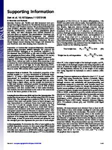
Finite Element Simulation. An SECM diffusion problem was solved in a dimensionless form by employing the finite element method as reported elsewhere.S-1 A tip current, iT, was normalized with respect to a limiting current at an inlaid disk tip in the bulk solution, iT(∞), to obtain a dimensionless tip current, IT, as
(S-1)
withS-2
(S-2)
The simulation results discussed in the main text are shown in Figures S-1, S-2, S-3, and S-4.
S-2
Figure S-1. Simulated iT–ES voltammograms based on the MHC formalism with λ* = 60 and log = (a, a') 1, (b, b') 0, (c, c') –1, (d, d') –2, (e, e') –3, (f, f') –4, (g, g') –5, (h, h') –6, (i. i') –7, (j. j') –8, and (k. k') –9. Dotted lines correspond to substrate potentials where 99 % of klim is achieved at 298 K (see eq 9).
S-3
Figure S-2. Simulated iT–ES voltammograms based on the MHC formalism with λ* = 20 and log = (a, a') 1, (b, b') 0, (c, c') –1, (d, d') –2, (e, e') –3, and (f, f') –4. Dotted lines correspond to substrate potentials where 99 % of klim is achieved at 298 K (see eq 9).
S-4
(a)
(b)
Figure S-3. Simulated substrate CVs based on (a) MHC formalism with λ* = 40 and (b) BV formalism with α = 0.5; log
= (a) 1, (b) 0, (c) –1, (d) –2, (e) –3, (f) –4, (g) –5, and (h) –6.
Curves a and b are reversible and overlap with each other. Dotted lines correspond to substrate potentials where 99 % of klim is achieved at 298 K (see eq 9). S-5
Figure S-4. Simulated iT–ES voltammograms based on BV kinetics with α = 0.5 and log
= (a,
a') 1, (b, b') 0, (c, c') –1, (d, d') –2, (e, e') –3, (f, f') –4, (g, g') –5, (h, h') –6, (i. i') –7, (j. j') –8, and (k. k') –9.
S-6
Analytical Equation for Irreversible Substrate Reactions (Eq 15). Eq 15 was used together with the following equations to calculate the retraceable portion of an iT–ES voltammogram when a substrate reaction is totally irreversible under the tip and opposite to the tip reaction (Figure S-5).S-3
(S-3)
(S-4)
with
(S-5)
S-7
Figure S-5. Simulated iT–ES voltammograms based on the MHC formalism (solid lines) with λ* = 40 and
= (a) 1 × 10⁻³ and (b) 1 × 10⁻⁵. Dashed and dotted lines represent iT–ES
voltammograms calculated using eqs 15 and 17 (or 18), respectively.
S-8
Analytical Equations for Quasi-Steady-State iT–ES Voltammograms (Eqs 17 and 18). Eqs 17 and 18 are valid under steady-state and quasi-steady-state conditions (Figure S-5), which are achieved when the reaction at the surface of a macroscopic substrate except under the tip is reversible or diffusion-limited as discussed in the main text. These analytical equations were derived using a model for an SECM-based thin layer cell as reported elsewhere.S-1 In contrast to a BV response, a limiting current based on the MHC mechanism can be controlled by ET kinetics rather than by mediator diffusion. To account for this difference, the normalized kinetic limiting current, IT,lim(L), and the corresponding limiting rate constant, klim, were introduced in eqs 17 and 18 to replace the diffusion-limited positive-feedback current at a tip, IT,d(L) (= IT,PF(L)), in the original equations based on BV kinetics.S-1 Eqs 17 and 18 are equivalent to the BV counterparts when klim → ∞ and, subsequently, IT,lim(L) → IT,d(L).
S-9
Table S-1. Reaction Parameters and Requirements for Observing a Kinetic Limiting Current at HOPG. redox couple
λ eV (λ*a)
k0 cm/sb
klim cm/sc
IT,lim/IT,PF at L = 0.25d d = 5 nm
0.5 (19)g 0.56 (22)h 0.6 (23)g 0.6 (23)g 0.8 (31)g 0.8 (31)g 0.9 (35)g 0.87 (34)i 1.0 (39)i 0.69 (27)j
>2.0 × 10⁻²
1.0 (39)g 0.78 (30)j 1.3 (51)g 1.13 (44)h 0.78 (30)j,k 0.7 (27)j,l
4.0 × 10⁻⁴
Ru(NH6)63+/2+
1.4 (54)g 1.3 (51)i 1.6 (62)i 0.58 (23)j
9.0 × 10⁻⁴
Co(phen)33+/2+
1.6 (62)g 1.48 (58)j
2.0 × 10⁻⁵
Ru(bpy)23+/2+ Fe(phen)33+/2+ MV2+/+ IrCl62–/3– Fc(COOH)2+/0 W(CN)83–/4–
Ru(CN)63–/4– Fe(CN)63–/4–
>7.0 × 10⁻² 1.7 × 10⁻² 3.0 × 10⁻³ 3.0 × 10⁻³ 4.0 × 10⁻⁴
1.0 × 10⁻⁶
>1.4 × 10 >2.7 × 10 >1.4 × 10² 3.5 × 10 4.9 × 10 4.9 × 10 1.8 × 10 1.3 × 10 5.0 × 10 2.1 5.0 × 10 5.3 2.6 9.4 × 10⁻¹ 1.3 × 10⁻² 5.8 × 10⁻³ 6.5 × 10³ 2.4 × 10³ 4.8 × 10⁴ 1.5 1.1 × 10³ 3.2 × 10²
E0' Vb, e
Vf
d = 50 nm
>0.67 >0.78 >0.95 0.82 0.86 0.86 0.71 0.65 0.87 0.31
>0.90 >0.94 >0.99 0.96 0.97 0.97 0.92 0.90 0.97 0.60
1.04
0.87
0.86 –0.67 0.74 0.42 0.33
1.01 1.01 1.28 1.28 1.41
0.87 0.47 0.35 0.18 0.12 0.12
0.97 0.78 0.65 0.33 0.13 0.13
0.78
1.55
0.25
1.95
1.0 1.0 1.0 0.27
1.0 1.0 1.0 0.53
–0.19
2.09
0.99 0.98
1.0 1.0
0.10
2.36
a
At 298 K. b Voltammetrically determined for HOPG in ref. S-4. c From eq 8. d From eq 15. e Approximate values against SCE as obtained by averaging voltammetric peak potentials on laser-activated glassy carbon electrodes. f Substrate potentials where 99 % of klim is achieved at 298 K (see eq 9). g Theoretically estimated for HOPG in ref. S-5. h Experimentally determined for SAM-modified gold electrodes in ref. S-6. i Experimentally determined for SAM-modified gold electrodes in ref. S-7. j Values in aqueous solutions calculated from photoelectron emission threshold energies in ref. S-8. k For ferrocyanide. l For ferricyanide. S-10
REFERENCES (S-1) Nioradze, N.; Kim, J.; Amemiya, S. Anal. Chem. 2011, 83, 828. (S-2) Lefrou, C. J. Electroanal. Chem. 2006, 592, 103. (S-3) Cornut, R.; Lefrou, C. J. Electroanal. Chem. 2008, 621, 178. (S-4) Cline, K. K.; McDermott, M. T.; McCreery, R. L. J. Phys. Chem. 1994, 98, 5314. (S-5) Royea, W. J.; Hamann, T. W.; Brunschwig, B. S.; Lewis, N. S. J. Phys. Chem. B 2006, 110, 19433. (S-6) Terrettaz, S.; Becka, A. M.; Traub, M. J.; Fettinger, J. C.; Miller, C. J. J. Phys. Chem. 1995, 99, 11216. (S-7) Becka, A. M.; Miller, C. J. J. Phys. Chem. 1992, 96, 2657. (S-8) Gorelsky, S. I.; Kotov, V. Y.; Lever, A. B. P. Inorg. Chem. 1998, 37, 4584.
S-11