Active Control of Under-actuated Foot Tilting for Humanoid Push Recovery Zhibin Li, Chengxu Zhou, Qiuguo Zhu, Rong Xiong, Nikos Tsagarakis, and Darwin Caldwell
Abstract—We propose a novel control framework to demonstrate a unique foot tilting maneuver based on ankle torque control for humanoid balance recovery. The framework consists of the variable impedance regulation at the center of mass of the robot based on the ankle torque control, the virtual stoppers to prevent over tilting of the feet, and the body attitude control. The scope of our paper focuses on the sagittal scenario as the first proof of concept on the balance recovery by means of active foot tilting without losing stability. Our study demonstrates the success of the control implementation for the humanoid push recovery and the feasibility of having actively controlled foot tilting. The experimental data are presented and analyzed.
I. I NTRODUCTION The biomechanical study of human locomotion reveals the existence of under-actuation phases during standing balancing and walking, and it is also a common observation and phenomenon that humans tilt the foot and roll around their toes under moderate forward pushes [1]. From mechanics point of view, the tilting of the support foot provides a good footground clearance that allows a maximum ankle torque to be applied. However, the humanoid robots, which are designed for utilizing human-orientated tools and traversing in human environment, have not demonstrated the standing balancing skills similar to humans, despite some humanoids have very comparable limb dimension and mass distribution to human companions. In terms of physics, there is no particular reason why humanoids could not perform similar standing balancing with under-actuation phases. Some practical factors that prevent them from doing so are because of the control techniques and the actuation technology. On the one hand, the common balance control demands the zero moment point (ZMP) (often referred during gait generation/planning stage) or center of pressure (COP) (often referred in terms of measurement) to be inside the support polygon. In this paper, we do not differentiate ZMP and COP because they are identical when it comes to a real system [2]. Once the foot tilts, the control challenge arises since the edge of the foot becomes the pivot which is an under-actuated degree of freedom (DOF), and the applied torque in this new DOF is always zero. The feasible range of COP vanishes to a singular point. From control theory, we lose the direct authority over this new DOF. Hence, to satisfy the preconditions of classical control, ZMP/COP must be constrained within the support polygon of a certain size. During the toe-off phases observed in human locomotion and passive dynamic walkers, the ZMP/COP lies inside the point support or a narrow support. Though ZMP is still the point where the resultant ground reaction force (GRF) passes,
the relation between the location of ZMP/COP and the polygon of support does not suffice as a criterion to reflect the level of balance by indicating whether or not a robot or a human is going to fall. Due to this limitation, other physical quantities based on the mechanical energy were proposed. Noticeably, the Capture Point is a simple but straightforward measure of balance [3]. Some gait control methods were also developed based on the Capture Point [4] [5]. The standing balance control can be classified into two categories by the actuation technologies. One is the position based control that typically utilizes a simplified low dimensional model, calculates the desired Cartesian references by satisfying contact force constraint such as ZMP, and obtains the position reference in joint space via inverse kinematics [6] [7]. The other is the torque based control that has the feedback loop of the targeted objectives at the Cartesian space and uses the joint torque capability to directly apply the desired wrench to deliver the control actions [8] [9]. Our proposed strategy belongs to the latter category. In this paper, we are inspired by the principle of the energy based stability criterion and its indication of feasible balance recovery by foot tilting. Our unique contribution is our proposed control framework that performs standing balancing with actively controlled under-actuation. We prove in a real system that there is no necessity to keep feet flat on the ground for retaining a large size of support polygon, nor to restrict the COP away from the edges. Rather, the COP is permitted to move to the narrow boundary of the contact polygon which can be reduced to a line. This result is encouraging because it shows the possibility towards the human-comparable balancing and walking with real toe-off motion for powered bipeds/humanoids. To the best of our knowledge, only Petman and Dexter robots have similar foot tilting performance. Unfortunately, no publications are ever disclosed. Hence, we are delighted to offer the first recipe to the robotic community as a proof of concept. Our study focuses on the sagittal balance control and has shed some light on the future improvement of the walking efficiency by using the Capture Point as a balance state indication and utilizing the torque controlled actuation to produce more natural gaits. The paper is organized as follows. Section II elaborates the principles of the mechanical energy based balance criterion and its suggestion of balance augmentation, the whole body COM feedback, and the ankle torque control. Section III presents the whole control framework including the variable COM impedance control, the virtual mechanical stoppers, and the upper body attitude control. Section IV shows the
Author’s preprint version for academic circulation only. foot segment, ω the angular velocity. Therefore, the virtual pendulum pointing from the frontal foot to the COM is rf = r0 − df , and the virtual pendulum pointing from the rear foot to the COM is rb = r0 − db . Given an instantaneous pivot, the vector pointing from the pivot to the COM is the equivalent pendulum that allows using the simplified IPM to analyze the balance status. When the total mechanical energy is lower than the maximum potential energy apex at the current foot-ground contact configuration, then the robot can have under-actuation phases and thus tip around the edge of the foot since the total energy is bounded. Define I the inertia tensor around an instantaneous pivot, neglecting the inertial tensor around the COM, resulting
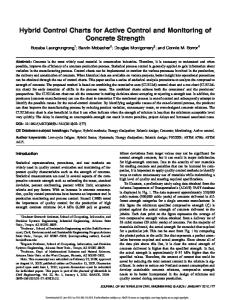
Φt Segmental COM Robot COM
ωhip
τankle (a)
(b)
(c)
I = m diag(ry2 + rz2 , rx2 + rz2 , rx2 + ry2 )
Fig. 1: KONG humanoid, its multi-mass model for COM estimation, and the simplified model for control.
(1)
where r is the equivalent pendulum rf or rb around the pivot. To code our algorithms, we used the general 3D vectors and 3 × 3 matrices for all computations, and assigned/applied only the sagittal components in this particular case study. The kinetic energy of the system Ek around the pivot is approximated by
successful push recovery with active and controlled foot tilting, and analyzes the experimental data. We discuss and conclude our study in Section V.
1 T ω Iω. (2) 2 When the equivalent pendulum r = rf,b travels from angle θ0 to θf as the case in Fig. 2, the gravitational work is
II. E NERGY BASED BALANCE I NDICATION AND THE I MPLICATION OF F EASIBLE U NDER - ACTUATION
Ek =
Following the prior work of measuring the energy state to determine the global stability of legged robots [10], we do not constrain the feet to be flat on the ground during balancing thus permit a better diversity of movements. Fig. 1(a) shows the life-size humanoid robot ‘KONG’. We describe a general 3D multi-mass model as in Fig. 1(b) that considers the distributed masses for computing the full body center of mass (COM) feedback. The arms are not used for our balance control study, so all the upper body masses are lumped as one equivalent mass. Fig. 1(c) shows the simplified model for the control design, where the COM is controlled by the ankle torque τankle for the global stability, and the torso orientation is independently controlled to be upright. The coupling effect introduced by the torso controller will be reflected on the COM and counterbalanced by the close-loop COM controller. The momentum effect of the torso is not yet considered in this study since both the angular rate and displacement are limited. Under large external force disturbances, the robot can tip around the edge of foot similar to an inverted pendulum. We hereby use the inverted pendulum model (IPM) to elaborate the concept of the energy based balance measure and its implication of balance augmentation.
Wg = mgkrk [cos(θ0 ) − cos(θf )] .
(3)
The potential apex is the position where the upright pendulum aligns with the gravity vector, where θf = 0. So potential energy can be written as Ep = mgkrk (cos(θ0 ) − 1)
(4)
regarding the potential apex as the zero potential point. Consequently, by examining the total mechanical energy E = Ek + Ep ,
(5)
we can determine whether or not the robot will roll over the edge of support foot according to classical mechanics: E = 0 indicates a perfect rest on the point of potential apex; E < 0 implies a turning back before the potential apex; and E > 0 means the COM will cross over potential apex and fall over. The above conclusion has a reasonably good prediction of the global balance state of the robot when the angular momentum around the COM is negligible and the gravitational torque is dominant. It is worth noticing that if a particular robot is able to produce large momentum equal to a flying wheel around the COM, then it will change the future evolution of the COM state and make the above conclusion invalid. However, this is not the case for our study here.
A. Mechanical Energy Based Balance Prediction Fig. 1(c) shows the planar model consists of a point mass m that accounts for the overall COM of the robot, and the trunk, inverted pendulum and foot are massless. The kinetic energy of the robot is computed by the proprioception using the measurements from the kinematics (motor encoder readings) and the inertial measurement unit (IMU) mounted in pelvis. Using the projection of ankle joint at the local coordinate of foot as in Fig. 2, denote r0 the virtual leg, df,b the front/back
B. Balance Augmentation by Active Foot Tilting To measure the standing stability by mechanical energy indicates the improvement of disturbance rejection by enlarging the potential apex. In a planar case of forward push recovery as shown in Fig. 2(a), if the robot keeps the same 2
Δz
F rf z
θf=0
r0
θ0
r0
df
db (a)
rf
xref +
θf=0
r0
PD Velocity Control
Variable Impedance Control
-
rf
ωd
Numerical Integration
τankle τd
+
+
-
-
τ τvirtual
df
df
(b)
(c)
xcom xcom
Φd
Admittance Based θd Torque Tracking
.
x y
Φ Φref + - t
τvs+τvd
Derivative
Inverse Kinematics
Author’s preprint version for academic circulation only.
θp
qd ωd
.
θp
τd
Fig. 3: The balance control scheme.
θa
Fig. 2: Balance argumentation by active foot tilting. where A is A(i) = Kd q0 (i) +
pose as one rigid body (Fig. 2(b)), then the virtual pendulum is rf = r0 − df , corresponding to the kinetic energy of mg(rf −r0 (z)) to pass over the potential apex. However, if the ankle joint actively rotates by θa with respect to the previous link and creates a foot tilting behavior as shown in Fig. 2(c), then the virtual pendulum becomes rf = r0 − Rpitch (θa )df . This results in an elongated virtual pendulum rf thus form a larger potential barrier, making the robot more difficult to be pushed over.
q0 (i) = θd (i − 1) −
τ (i) τd (i) + . Ks Kd
(8)
Substitute (8) into (6) and (7), yields θd (i) = θd (i − 1) +
τ˙ (i) +
Ks Kd Bd
Ks T
+
τd (i) − τ (i) Kd + BTd
(9)
The torque loop compares the error between the reference τd and the measurement τ , and incrementally modulates the position reference of the actuator to thrust the desired torque. For the rubber pads used in feet, the equivalent physical stiffness Ks was about 1500N m/rad, so the maximum Kd was no larger than 1000N m/rad. The √ desired viscous coefficient Bd was tuned proportionally to Kd with a minimum damping ratio to guarantee the necessary passivity for avoiding unstable oscillations. θd was used to update the orientation of both feet in the inverse kinematics calculation.
To close the impedance loop at the COM for computing the desired ankle torque for balance recovery, the COM estimation of the real robot is needed. The COM position feedback was computed by the forward kinematics of the robot using the motor encoder readings combined with the orientation of the pelvis measured by the IMU. The COM velocity was obtained by differentiating the successive COM positions. The lower body segmental COM of the KONG robot was obtained from the mechanical design software, and was approximately at the center of each limb. The torso’s COM vector had big variations due to the on-board equipments and was calibrated via least square fitting by using the COP measurement in the feet as the reference during very static movements. Given the limited range of motion during push recovery, we have validated the COM estimation which had reasonable accuracy. The COM state was also used to compute the Capture Point in the following experiments to indicate the level of stability.
III. S TANDING BALANCE C ONTROL S CHEME To demonstrate the feasibility of balance control involving active under-actuation, we designed a control framework consisting of the variable impedance control at the COM, the virtual mechanical stoppers, and the body attitude control, as shown in Fig. 3. It shall be clarified that this scheme allows foot tilting due to the excessive ankle torque. As a positive byproduct, the apex was heightened, however, the controller had not yet targeted the control of apex height purposely.
D. Transforming Position Control Into Torque Control
A. Variable Impedance Control at the COM
In order to achieve impedance control at the COM, the torque control in ankles is desired. Despite the KONG robot has position controlled motors, the F/T sensors in feet allow us to transfer the ankle joints to be torque controlled. We adopted the admittance controller in [11]. Define θd as the desired pitch of the foot in the discrete form at the ith control loop, T as the sampling time, τ (i) as the real torque measurement, and Ks , Kd as the physical and desired stiffnesses (Ks > Kd ), the admittance controller is T Bd A(i) + θd (i − 1), K d T + Bd Kd T + Bd
(7)
The torque tracking was realized by offsetting the equilibrium point q0 (i) in (7) as
C. Whole Body COM Estimation
θd (i) =
Kd − Ks Bd τ (i) + τ˙ (i). Ks Ks
Given the COM state feedback as in Section II-C, an impedance feedback control can be designed and the computed desired recovery ankle torque can be tracked by the torque loop as in Section II-D. We have learned empirically that the qualitatively optimal impedance regulation is to be compliant when the stability margin is large and to be stiff when the stability margin is small. Therefore, we designed the impedance control gains to be variable. Ideally, the Capture Point shall be used as the stability indication for varying the impedance gains, however, we found that the ripples in the velocity component of the Capture Point
(6) 3
net torque as if the real mechanical stoppers were applied:
1000 900 800 700 Stiffness 600 0.08 0.06 0.04 0.02 0.00 0.02 0.04 0.06 0.08 0.10 0.12 0.14
Gain [Nms/rad]
Gain [Nm/rad]
Author’s preprint version for academic circulation only.
τvs = −Kpv θp3 , −kθp kKdv θ˙p , when θp > 0 & θ˙p > 0 τvd = or θp < 0 & θ˙p < 0 0, otherwise.
155 145 135 Viscous damping 125 0.08 0.06 0.04 0.02 0.00 0.02 0.04 0.06 0.08 0.10 0.12 0.14 Position of COM [m]
Variable Impedance Control
τankle -τankle
(11)
Define θth as the angular threshold where the generated virtual torque from the virtual spring will decrease the commanded torque down to the ideal torque limits determined by the weight of the robot as mgkdb k and −mgkdf k respectively. Hereby, the torque limits for impedance loop was configured such that this cancellation can be reached when the feet have reasonable clearance off the ground (i.e. θth = 20◦ ), � 3 τmax = mgkdb k + Kpv θth , (12) v 3 τmin = −mgkdf k − Kp θth .
Fig. 4: Variable impedance gain regulation.
-τankle
(10)
If the foot starts to tilt more than θth , then the nonlinear ‘mechanical stopper’ will drastically produce a large torque to deduct from the desired torque command sending to the torque tracking loop. Hence, the over tilting of the foot will be suppressed effectively.
Virtual Stopper
τvs+τvd θp
C. Upper Body Attitude Control The torso attitude is regulated by a velocity control that commands the velocity reference in proportional to the orientation error. The desired body posture is to keep the body pitch and roll angles at zero. The body posture is controlled by generating a reaction torque at the hips. This is realized indirectly by controlling the rate of change of the orientation of the body in the inverse kinematics � ωd (i) = kp (φref (i) − φt (i)) − kd φ˙ t (i), (13) φd (i) = φd (i − 1) + ωd (i)T,
Fig. 5: Virtual mechanical stopper that prevents over tilting.
will produce a chain reaction of instability from the viscous damping torque computed from the COM velocity feedback. Therefore, in this paper, we only used the COM position component for the variable gain calculation as a compromise. Fig. 4 shows the torsional impedance for the ankle converted from the Cartesian impedance at the COM. The ankle torque here is defined as the torque applied to the equivalent COM pendulum, and the output torque saturation has the limits higher than the torque created by the weight of the robot, that is τmax > mgkdb k and τmin < −mgkdf k. In such a way, the feet are able to tilt. The calculation of τmax and τmin will be explained in the following section.
where φt and φ˙ t are the measured angle and rate of the body pitch, kp and kd are the control gains (kp =2.0, kd =0.2 in the following experiments). The updated body orientation φd is obtained by numerically integrating the desired angular velocity command ωd . IV. E XPERIMENTAL VALIDATION
B. Virtual Mechanical Stopper: Nonlinear Spring-Damper
Fig. 6 shows the evaluation of torque tracking performance at 0.5Hz, 1.0Hz, and 1.5Hz respectively. The control parameters were Ks = 1500N m/rad, Kd = 1000N m/rad, and Bd = 60N m · s/rad, where Kd and Bd were constant for the tests of torque tracking control. The torque tracking was reasonable for a position controlled based actuation system and sufficient for the standing balancing task. Fig. 7 shows the snapshots from the successful push recovery experiment. The under-actuation phase is marked in both overall and close-up views. The active ankle torque control can be intuitively seen from the accompanied video where the motor spins rapidly during under-actuation phase to perform the control action to dissipate excessive kinetic energy delivered by the disturbance. Fig. 8 presents the data from the trial with an underactuation period about 2 more seconds. Fig. 8(a) shows that the
Without any additional constraints, setting τmax and τmin larger than the counteracting gravity torque would cause the foot over tilt when a very large ankle torque is commanded. Besides, it is also common to have unstable oscillations known as a ‘chattering problem’ in real systems, especially when the torque tracking bandwidth is not very high. We have investigated a variety of different techniques to suppress these unstable oscillations and to prevent over tilting. The most neat, simple, yet effective method we found was to place the nonlinear virtual spring-dampers at the feet as the virtual ‘mechanical stoppers’ to generate unilateral torque based on the pitch angle θp measured from feet with respect to the ground, as shown in Fig. 5. This computed virtual torque was used to deduct the desired ankle torque from the impedance loop, thus resulted in an equivalence of reduced 4
Author’s preprint version for academic circulation only.
Push
Tilting 0s
Tilting
Tilting
4/3s
6/3s
2/3s
8/3s
10/3s
12/3s
10/3s
12/3s
(a) Successful balance recovery that under a large push.
Tilting
Tilting
Tilting
2/3s
4/3s
6/3s
0s
8/3s
(b) Close view of under-actuation.
Torque [Nm]
Fig. 7: Experiments of push recovery with active control of under-actuation.
15 10 5 0 −5 −10 −15 0.0 15 10 5 0 −5 −10 −15 0.0 15 10 5 0 −5 −10 −15 0.0
robot. During the initial phase of being pushed over (0.4s to 0.6s), the body orientation was disturbed to 8◦ at an instant angular rate more than 20◦ /s. However, during the major portion of the under-actuation phase, the body attitude controller was able to converge the body pitch back to zero at about −5◦ /s speed. After the under-actuation phase, the body pitch was quickly stabilized around zero. Fig. 8(c) provides the averaged pitch angle and angular rate of both feet during the push recovery. It clearly shows the under-actuation that the feet rotated up to 10◦ with respect to the horizon and the spinning rate was close to 30◦ /s. The red line in Fig. 8(d) was the desired torque reference computed by the impedance loop compared to the real ankle torque measured from the left and right foot. It should be noted that there were some high-frequency ripples occurred in the ankle torque during the under-actuation phase, and later there were some low-frequency ripples of about 2Hz during the stance phase. This was due to coupling effect of the real dynamics undergoing in three dimensional space reflected in both the sagittal and the lateral planes. Fig. 9(a) shows the measurement of the normal force components from the F/T sensors. The scope of our paper was focused on the sagittal balance control as a proof of concept, thus there was no controller that stabilized the lateral motion. The Cartesian COM impedance controller distributed the total reference torque to the right and left ankles equally, thus it had a precondition that the normal ground reaction forces were the same for both feet. However they were never ideally the same in practice.
Reference Left ankle Right ankle 0.5
1.0
1.5
2.0
2.5
3.0
3.5
4.0
4.5
5.0
0.5
1.0
1.5
2.0
2.5
3.0
3.5
4.0
4.5
5.0
0.5
1.0
1.5
2.0
2.5 3.0 Time [s]
3.5
4.0
4.5
5.0
Fig. 6: Experiments of ankle torque tracking control.
COP moved to the front and stayed almost constantly for about 2s, which indicated the COP resided around the narrow rubber edge of the foot. The energy based stability measurement, Capture Point, remained inside the projection region of support foot all the time. This meant that the mechanical energy of the robot was bounded and the robot would not fall over even when the feet tilted and the COP shifted to the edge of the support foot. The COM data is also shown as a comparison to the Capture Point. Fig. 8(b) shows the pitch angle and angular rate directly measured by the IMU sensor installed on the pelvis of the 5
Author’s preprint version for academic circulation only.
0.15
0.05
Force [N]
Position [m]
0.10
COP Capture Point COM
0.00 0.05 0.100.0 0.5 1.0 1.5 2.0 2.5 3.0 3.5 4.0 4.5 5.0 5.5 6.0 6.5 7.0 7.5 8.0 Time [s]
Time [s]
(a) Measurements of COP, Capture Point and COM.
15
(a) Vertical ground reaction force.
Body pitch Body pitch rate
Roll [deg]; Roll rate[deg/s]
Pitch [deg]; Pitch rate[deg/s]
20 10 5 0 5 10 15
200.0 0.5 1.0 1.5 2.0 2.5 3.0 3.5 4.0 4.5 5.0 5.5 6.0 6.5 7.0 7.5 8.0 Time [s]
Pitch [deg]; Pitch rate[deg/s]
(b) Body roll angle and its angular rate.
Fig. 9: Coupling effects of sagittal and lateral dynamics on the ground reaction forces that caused ripples in the ankle torque tracking.
30 Foot pitch 25 Foot pitch rate 20 15 10 5 0 5 10 15 20 25 300.0 0.5 1.0 1.5 2.0 2.5 3.0 3.5 4.0 4.5 5.0 5.5 6.0 6.5 7.0 7.5 8.0 Time [s]
robot rocked back and established new foot-ground contacts, the whole system had oscillations in all planes and only the energy in the sagittal plane was effectively attenuated. The lack of lateral stabilization control also resulted in the fluctuation of the roll angular rate as shown in Fig. 9(b). This suggests our future work to implement the same control approach to the three dimensional stabilization.
(c) Foot pitch angle of left and right foot. 35
Torque [Nm]
15
4.5 Roll 3.5 Roll rate 2.5 1.5 0.5 0.5 1.5 2.5 3.5 4.5 5.5 6.50.0 0.5 1.0 1.5 2.0 2.5 3.0 3.5 4.0 4.5 5.0 5.5 6.0 6.5 7.0 7.5 8.0 Time [s]
(b) Body pitch angle and angular rate.
25
450 Fz right 400 Fz left 350 300 250 200 150 100 500.0 0.5 1.0 1.5 2.0 2.5 3.0 3.5 4.0 4.5 5.0 5.5 6.0 6.5 7.0 7.5 8.0
V. D ISCUSSION AND C ONCLUSION
Reference Left ankle Right ankle
Our study demonstrates the feasibility and success of actively creating an under-actuation phase using ankle torque control for balance recovery. In this particular case, the COP is restricted inside a narrow line at the edge of the feet. Hence, the geometric relation of the COP with respect to a large area of support polygon can no longer be a reasonable balance criterion, because the COP is always at a singular point and there is no geometric distance that can be used as an indicator. Instead, the energy based stability criterion, the Capture Point for example, was used to indicate the balance status of the robot and was in agreement with all real experimental results. The forward and backward pushes produced very similar experimental data. Therefore, due to the limited pages, we have only reported the experiments in the case of forward push. In the future, we plan to extend current approach to exploit the use of toes for a humanoid. Since our initial investigation was conducted in the sagittal plane, we will also extend the
5 5 15 25 35 450.0 0.5 1.0 1.5 2.0 2.5 3.0 3.5 4.0 4.5 5.0 5.5 6.0 6.5 7.0 7.5 8.0 Time [s]
(d) Torque tracking of left and right ankle pitch joint.
Fig. 8: Experimental data of successful push recovery.
In reality, the push applied in the forward direction also produced the disturbance on the lateral plane unavoidably, thus the robot oscillated slightly in the lateral direction. This was very obvious especially after 3s in Fig. 9(a) when the 6
Author’s preprint version for academic circulation only.
control framework to stabilize the lateral motion by controlling the ankle torque as well as the torque created by the differential leg forces. Besides, we are also interested in quantifying the maximum force disturbance that can be withstood as well as benchmarking against the controllers without producing foot tilting. ACKNOWLEDGMENT This work is supported by the FP7 European project WALKMAN (ICT 2013-10) and the Open Project 2013 (ICT-1321) from the Zhejiang University. R EFERENCES [1] D. A. Winter, Biomechanics and motor control of human movement. John Wiley & Sons, Inc., 2009. [2] M. Popovic, A. Goswami, and H. Herr, “Ground Reference Points in Legged Locomotion: Definitions, Biological Trajectories and Control Implications,” The International Journal of Robotics Research, vol. 24, no. 12, pp. 1013–1032, Dec. 2005. [3] J. Pratt, J. Carff, S. Drakunov, and A. Goswami, “Capture point: A step toward humanoid push recovery,” in IEEE-RAS International Conference on Humanoid Robots, December 2006, pp. 200–207. [4] J. Englsberger, C. Ott, M. Roa, A. Albu-Schaffer, and G. Hirzinger, “Bipedal walking control based on capture point dynamics,” in IEEE/RSJ International Conference on Intelligent Robots and Systems, 2011, pp. 4420–4427. [5] M. Morisawa, S. Kajita, F. Kanehiro, K. Kaneko, K. Miura, and K. Yokoi, “Balance control based on capture point error compensation for biped walking on uneven terrain,” in IEEE-RAS International Conference on Humanoid Robots, 2012, pp. 734–740. [6] D. N. Nenchev and A. Nishio, “Ankle and hip strategies for balance recovery of a biped subjected to an impact,” Robotica, vol. 26, no. 5, pp. 643–653, 2008. [7] Y. Wang, R. Xiong, Q. Zhu, and J. Chu, “Compliance control for standing maintenance of humanoid robots under unknown external disturbances,” in IEEE International Conference on Robotics and Automation (ICRA), 2014, pp. 2297–2304. [8] C. Runge, C. Shupert, F. Horak, and F. Zajac, “Ankle and hip postural strategies defined by joint torques,” Gait & Posture, vol. 10, no. 2, pp. 161–170, 1999. [9] C. Ott, M. Roa, and G. Hirzinger, “Posture and balance control for biped robots based on contact force optimization,” in 11th IEEE-RAS International Conference on Humanoid Robots, Bled, Slovenia, 2011, pp. 26–33. [10] Z. Li, C. Zhou, J. Castano, X. Wang, F. Negrello, N. G. Tsagarakis, and D. G. Caldwell, “Fall Prediction of Legged Robots Based on Energy State and Its Implication of Balance Augmentation: A Study on the Humanoid,” in IEEE International Conference on Robotics and Automation, 2015. [11] Z. Li, N. Tsagarakis, and D. Caldwell, “Stabilizing humanoids on slopes using terrain inclination estimation,” in IEEE/RSJ International Conference on Intelligent Robots and Systems (IROS), 2013, pp. 4124– 4129.
7