JOURNAL OF TELECOMMUNICATIONS, VOLUME 10, ISSUE 2, SEPTEMBER 2011 27
A Performance Enhancement of IEEE 802.11a OFDM Standard Model Abdul-Salam Mohammed Abood Abstract—In this paper, the Doppler frequency estimated for orthogonal frequency division multiplexing (OFDM) systems in time-varying multipath channels. The proposed scheme is a time-domain approach that utilizes pilot subcarriers, which are commonly implemented in most practical systems and the estimation be done in time domain due to using the blocks of fast Fourier transform (FFT) and its inverse (IFFT) at the transmitter and the receiver sides respectively, in addition to those standard blocks. Time-varying fading causes intercarrier interference (ICI) in OFDM systems. Thus, in the proposed algorithm, the effect of ICI is taken into consideration with a proper model for accurate results. The proposed algorithm can be implemented by simple addition and subtraction blocks based on shifting the data horizontally and adding them vertically (sub-blocks).We evaluate the system performance in flat fading and the AWGN channel to prove the effectiveness of the proposed model. The simulation results show that the proposed algorithm enhanced the system performance in terms of bit error rate (BER), thus it can be considered as alternative technique to the standard model.
Keywords: FFT, IFFT, Flat fading, AWGN, ICI, BER
—————————— � ——————————
1 INTRODUCTION Orthogonal frequency division multiplexing (OFDM) has been adopted by many wireless standards such as IEEE 802.11 and 802.16 and has been implemented in many practical systems. The maximum Doppler frequency (fd) is the ratio of the speed of the mobile user and the wavelength of the carrier. Knowledge of mobile speeds is critical in improving the performance of multi-cell wireless communication systems. For example, in the pico-cell deployment overlaying with existing macro-cells, the Doppler frequency information of each mobile allows optimization of user assignments to proper base stations, and thus minimizes the number of handover scenarios. The mobile speed information is also very critical for implementing a number of physical- and network-layer functions such as adaptive and fast link adaptation, and accurate channel prediction. Thus, the scheduler gain due to multiuser diversity and spectral efficiency of the system can be increased [1]. In [2], an autocorrelation-based scheme for maximum Doppler-frequency estimation was proposed for singlecarrier systems, where the estimate is obtained using the envelope of the received signal. In [3], a method based on the differentials of the channel estimates is employed for the estimation process. Another method based on the level-crossing rates was proposed in [4]. In most OFDM systems, a cyclic prefix (CP), which is the replica of the OFDM symbol tail, is used as the guard interval. In [5], the correlation between the tail of the OFDM symbol and the guard interval was exploited to estimate fd, where the effects of intersymbol interference (ISI) was not considered. In [6], the estimate of fd is obtained via a maximum-likelihood (ML) based time-domain method for TDMA and CDMA systems. The application of this algorithm to OFDM systems was presented in [7], where time domain channel estimates were used to obtain the maximum Doppler frequency estimates.
In [8] a proposed receiver structure that alleviates the problems of highly Doppler frequency Mobile underwater OFDM by estimating (and correcting for) the Doppler rate on a symbol-by-symbol basis. The transmitted block of OFDM symbols is preceded by a preamble that allows for initial timing and Doppler rate estimation. Joint carrier frequency offset and channel estimation are then performed on the first symbol assuming that the Doppler rate estimated during the preamble is equal to the actual Doppler rate during the first OFDM symbol. In [9] a sliding window (SW) technique was proposed for enhancing the system performance of the OFDM modem for the physical layer of IEEE 802.11a standard. The performance of such system was improved under the flat and the AWGN channel. Two blocks of FFT and sliding window were used at the transmitter side and the inverse of these blocks at the receiver side in addition to the other main blocks (i.e. IFFT at the transmitter side and FFT at the receiver side). The SW block of length 64-bits was used in [9] which is the same size of FFT block. In this paper, we split the block of sliding window into sub-blocks (sliding blocks) based on shifting the data vector bit-by-bit to the right in the transmitter side and adding them vertically as shown in section 4. The transmitted vector of length N will be divided into 4-subsets and we apply the sliding blocks and the IFFT on each subset. The output of each subset after the sliding block will be processed by the FFT block, these additional sub-blocks (FFT) will increase the orthogonality of subcarriers and then will enhance the system performance. The reverse steps will be applied at the receiver to recover the transmitted signal, which means in addition to the sliding blocks; we will add the FFT blocks at the transmitter and its inverse at the receiver.
————————————————
• Abdul-Salam Mohammed Abood Author is with Electrical Engineering Department, College of Engineering ,University of Anbar, IRAQ © 2011 JOT www.journaloftelecommunications.co.uk
28
2. The Standard IEEE 802.11a The IEEE 802.11 specification is a wireless LAN (WLAN) standard that defines a set of requirements for the physical layer (PHY) and a medium access control (MAC) layer. For high data rates, the standard provides two PHYs - IEEE 802.11b for 2.4-GHz operation and IEEE 802.11a for 5-GHz operation [10]. The IEEE 802.11a standard is designed to serve applications that require data rates higher than 11 Mbps in the 5-GHz frequency band. The wireless medium on which the 802.11 WLANs operate is different from wired media in many ways. One of those differences is the presence of interference in unlicensed frequency bands, which can impact communications between WLAN NICs. Interference on the wireless medium can result in packet loss, which causes the network to suffer in terms of throughput performance. Current 2.4-GHz 802.11b radios handle interference well because they support a feature in the MAC layer. When developing WLAN systems, choosing the right modulation and frequency band should be a priority in RF design, especially when designing IEEE 802.11a radios. For the past decade, WLAN systems have been designed to operate in the unlicensed 2.4-GHz frequency band. The 2.4-GHz band provides 83 MHz of total contiguous bandwidth, spanning from 2.4 to 2.483 GHz. Moving to the 5-GHz band offers over three times the operating bandwidth over the available spectrum in the 2.4GHz band. The 5-GHz band is also less susceptible to interference, unlike the 2.4-GHz unlicensed band, which shares spectrum with other wireless appliances such as Bluetooth devices [10]. During the development of the 802.11a specification, ESTI was charging ahead with a 5-GHz WLAN project called Hiperlan2. They too adopted OFDM. For the most part, the PHY for 802.11a is similar to Hiperlan2. The differences between the two standards are minimal and reside in the method by which convolution encoding is used to generate the OFDM symbols and data rates. But it has been said that by making the convolution encoder a programmable feature in the baseband processor, the same silicon can be used to support both standards. This is an extremely attractive feature for those who want to develop products for both standards. Unfortunately, the MAC layers are very different. In the U-NII band, eight carriers are spaced across 200 MHz in the lower spectrum (5.150 - 5.350 GHz) and four carriers are spaced across 100 MHz in the upper spectrum (5.725 - 5.825 GHzThe channels are spaced 20 MHz apart, which allows for hi). gh bit rates per channel. The channel scheme used for 5 GHz is illustrated in fig. (1) [10].
the guard interval is equal to 800 ns, which provides excellent performance on channels with delay spread of up to 250 ns. To efficiently use the spectrum provided in the 5-GHz range, designers of IEEE 802.11a systems use OFDM techniques. OFDM is a unique form of multicarrier modulation. The basic concept is to transmit high data rate information into several interleaved, parallel bit streams and let each of these bit streams modulate a separate sub carrier. In this way, the channel spectrum is passed into a number of independent, non-selective frequency sub-channels for transmission between wireless NICs and access points. The OFDM modulation technique is generated through the use of complex signal processing approaches such as fast Fourier transforms (FFTs) and inverse FFTs in the transmitter and receiver sections of the radio. One of the benefits of OFDM is its strength in fighting the adverse effects of multipath propagation with respect to intersymbol interference in a channel. OFDM is also spectrally efficient because the channels are overlapped and contiguous. OFDM is well tested and has been adopted by a number of standards bodies for several applications, including a wired global standard for asymmetric digital subscriber line (ADSL) and for digital audio broadcasting (DAB) in the European market [10]. To complement OFDM, the IEEE 802.11a specification also offers support for a variety of other modulation and coding alternatives. For example, the standard allows engineers to combine BPSK, QPSK, and 16-QAM modulations with convolution encoding (R = 1/2 and constraint length seven) to generate data rates of 6, 12, and 24 Mbps. All other combinations of encoding rates, including R = 2/3 and R = 3/4 combined with 64-QAM, are used to generate rates up to 54 Mbps, which are optional in the standard. During development of the 802.11a standard, the IEEE 802.11 working group carefully optimized the PHY for traffic transmitting multimedia content such as streaming video. The packet date frame defined in the 802.11a specification consists of the PHY header, PHY layer convergence protocol (PLCP) and the payload (PSDU). This is similar to the structure used in the IEEE 802.11b specification. The first field of the PLCP header is called the preamble. The preamble consists of 12 symbols, which are used to synchronize the receiver. The second field is the signal field. The signal field is used to indicate the rate at which the OFDM symbols of the PSDU payload are transmitted. The PLCP header is always BPSK modulated and convolution encoded at R = 1/2. The PSDU packet payload is modulated and transmitted at the rate indicated in the signal field. This rate is variable from 6 up to 54 Mbps. The structure of the packet data frame is illustrated in fig. (2) [10].
Fig. (1): IEEE 802.11a frame format for 5 GHz. fig. (1) illustrates, there are 52 subcarriers per channel in the 5-GHz band [10]. Only 48 subcarriers carry actual data. The remaining four subcarriers are used as pilot tones, which assist in phase tracking for coherent demodulation. The duration of
Fig. (2): IEEE 802.11a channel scheme
29
3. OFDM General Structure The basic principle of OFDM is to split a high-rate data stream into a number of lower rate streams that are transmitted simultaneously over a number of subcarriers. The relative amount of dispersion in time caused by multipath delay spread is decreased because the symbol duration increases for lower rate parallel subcarriers. The other problem to solve is the intersymbol interference, which is eliminated almost completely by introducing a guard time in every OFDM symbol. This means that in the guard time, the OFDM symbol is cyclically extended to avoid intercarrier interference. An OFDM signal is a sum of subcarriers that are individually modulated by using phase shift keying (PSK) or quadrature amplitude modulation (QAM). The symbol can be written as
4. Modified Structure The standard window size N=64 is used according to the parameters given in section (2) for 5-GHZ band (i.e. IEEE 802.11a). This window size is divided into 4 parts of length 16-bits each. A sliding block technique will be applied on each part [9]. The block of FFT used in [9] at the transmitter side before sliding block will be used directly after sub-sliding blocks. To reduce the round of error, the sliding blocks divided into sub-sliding blocks of length 16-bits each. The sliding block technique is used for enhancing the system performance under the Doppler frequency effect and in the AWGN channel. The main added blocks to the standard model is shown in fig. (4). The output data vector and training after the QAM modulator are of length 52 bit in addition to the other 12 bits from 53 to 64 used for synchronization or zero padding. We set these bits to zero, and the total vector length before applying IFFT is:
X 1 = [x1:N ]
(1)
(3)
Where Ns is the number of subcarriers, T is the symbol duration, and fc is the carrier frequency. The equivalent complex baseband notation is given by:
(2) In this case, the real and imaginary parts correspond to the inphase and quadrature parts of the OFDM signal. They have to be multiplied by a cosine and sine of the desired frequency to produce the final OFDM signal. Fig. (3) shows the block diagram for the OFDM modulator.
Fig. (3): OFDM modulator The complex baseband OFDM signal defined the equation (1) is the inverse Fourier transform of Ns QAM input symbols. The time discrete case is the inverse discrete Fourier transform. In practice, this transform can be implemented very efficiently by the inverse fast Fourier transform (IFFT). The IFFT drastically reduces the amount of calculations by exploiting the regularity of the operations in the IDFT.
Fig. (4): Main added blocks at the transmitter and the receiver sides of the standard model Now, the vector in (3) will be divided into 4-equally groups of length 16 each as given in [15]. The processing steps for sub-sliding blocks are the same as that given in [15]. The output data vector from each sub-sliding blocks will be processed by the additional four sub-blocks, which are the FFT blocks for increasing the orthogonality of subcarriers and leads a reduction in the bit error rate (BER). The output from the first FFT block is:
x1 (n) =
1 T
Nl 4 −1
∑
x k ( n )e
j 2π
kn N /4
,
0 ≤ n < N / 4 (4)
k =0
The output from the second FFT block is:
x2 (n) =
1 T
Nl 2 −1
∑ k =N / 4
xk (n)e
j 2π
kn N /4
,
N / 4 ≤ n < N / 2 − 1 (5)
30
The output from the third FFT block is:
x3 (n) =
1 T
N − N / 4 −1
∑
xk (n)e
j 2π
kn N /4
5. SIMULATION RESULTS , N / 2 ≤ n < N − N / 2 − 1 (6)
k=N / 2
The last equation for FFT block at the transmitter side is:
x4 (n) =
1 T
N −1
∑ xk (n)e
j 2π
kn N /4
, N − N / 4 − 1 ≤ n < N − 1 (7)
In this section, the performance of the proposed and standard models can be tested under the Doppler frequency (flat fading) and AWGN channel. Most of the standard parameters mentioned in section (2) can be summarized in table (1) [9], [13], [14] and [15].
k = N − N / 4 −1
The output data vector will be of length 64 bit taken from equations (4) to (7) and it can be converted from frequency to time domain by using the IFFT block as in the conventional model. In practical channel model, a random signal always added to the received data, the random added signal to the received data has more effect on the analogue signal than digital [11]. In our suggested method, the signal shape more smother and approached to the digital signal shape than the output of the transmitted data in the conventional model. This will reduce the BER in the proposed model relative to the conventional one. As the input signal varies, then the transmitted signal shape will also vary, but the above properties of the proposed model don't change. At the receiver side, the inverse steps will be applied in order to recover the transmitted signal, where the last step in the transmitter side is the first step at the receiver side and so on. The first step at the receiver side is removing the cyclic prefix and serial to parallel conversion. The second step is to convert the received vectors from time domain to frequency domain by using the FFT processor. The output data from the FFT block will be of length 64 bit. Now we can apply the reversing of sub-sliding blocks [15]:
y1 = y1, y2 = y2 − y1, y3 = y3 − y2, y4 = y4 − y3, ........ yN = yN − yN−1
(8)
The output data vector from (8) will be divided into 4equally parts of length 16-bit each, and then we apply the IFFT sub-blocks on each data sub-set as in next equation.
0 ≤ IFFT 1 ≤ ( N / 4) − 1 N / 4 ≤ IFFT 2 ≤ ( N / 2) − 1
(9)
N / 2 ≤ IFFT 3 ≤ N − ( N / 4) − 1 N − ( N / 4) ≤ IFFT 4 ≤ N − 1 Note that the output data vector in (9) has length of 64 bit. The training sequence is used to estimate the channel frequency response by dividing the received training samples on the transmitted training samples [9], [12]. The training sequence length can be increased from 4 bit to 48 bit such that it will have the same length of data vector of the main active subcarriers (48-bits). The channel frequency response is used to compensate the channel effect on the data by multiplying the received data by the inverse of the channel estimated vector bit by bit from 1 to 48 for each packet. After the channel compensation step, now the signal is demodulated by QAM demodulator and according to the number of constellation mapping points used at the transmitter side.
TABLE 1 SIMULATION PARAMETERS Modulation Type=QAM
M=16, 64
Guard Period Doppler spread Pilot subcarriers Number of effective sub-carriers Number of transmitted symbols Channel frequency Data rate
8-bits 10, 500 Hz 4 48 16800 5.2 GHz 54 Mbps AWGN Flat ing+AWGN
Channel model
.
fad-
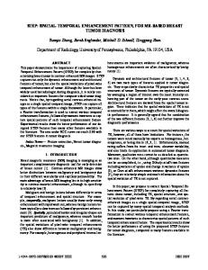
5.1 Evaluation of Models in AWGN Channel The systems performance of the proposed and standard models at the AWGN channel is shown in fig. (5). This figure shows their performances under two values of constellation mapping points which are M=16, and M=64 point. From this figure, It can be seen that the modified model based on SSW technique and FFT blocks has a BER=10-2 at SNR=28dB, while the conventional model has the same BER at 37dB, which means that the obtained gain is 9dB from the proposed model. As the number of constellation mapping (M) increases from 16 to 64 (dotted curves), the BER rate for both models will also increase. A wide span gain between the performances of these models, so the modified model is better and more significant than the conventional system at the AWGN channel. The BER increases in the same level for both models, and this insures that the modified model has a stable performance related to the conventional system. Note that there is a gain of 3dB obtained from the proposed model even the constellation points increased from 16 to 64 point when we compare its performance relative to the standard model at M=16 and BER=10-2.
0
10
0
Standard, M=16 Standard, M=64 Proposed, M=16 Proposed, M=64
10
Standard, Fd=10Hz Standard, Fd=500Hz Proposed, Fd=10Hz Proposed, Fd=500Hz
31
-1
10
-1
BER
BER
10
-2
10
-2
10
-3
10
5
10
15
20 SNR (dB)
25
30
35
40
Fig. (5): Performance of standard and proposed models at the AWGN channel 5.2 Evaluation of Models in Flat Fading Channel The performance of models can be now testing under the effect of Doppler frequency. Two values of Doppler frequencies are taken into consideration (10Hz and 500Hz), also the number of constellation mapping (M) are taken into account. The performance results of both models in terms of BER at M=16 is shown in fig. (6). From this figure, it can be seen that there is a gain of 9dB obtained from the proposed model at BER=10-2 and Doppler frequency=10Hz. The blue line represents the performance of the proposed model, while the black line with circle represent the standard system performance. As the Doppler frequency increases to 500Hz, the BER for both models increases, but the proposed model is still outperforms the standard one. In all range of SNR, the proposed model outperforms the system performance of the standard model. Fig. (7) shows the performance of models as the number of constellation mapping increases to 64 point. From this figure, there a wide span gain be obtained from the proposed model in all range of SNR at Doppler frequency=10Hz and 500Hz. The standard model has unacceptable performance or poor performance at M=64. From the simulation results, it can be considered the proposed model as an alternative technique to the standard model. 0
10
Standard, Fd=10Hz Standard, Fd=500Hz Proposed, Fd=10Hz Proposed, Fd=500Hz -1
BER
10
-2
10
-3
10
5
10
15
20 SNR (dB)
25
30
35
40
Fig. (6): Performance of models in flat fading channel (constellation points (M) =16)
-3
10
5
10
15
20 SNR (dB)
25
30
35
40
Fig. (7): Performance of models in flat fading channel (Constellation points (M) =64
6. Conclusion In this paper, a proposed method was in introduced to enhance the performance of the standard OFDM model for the physical layer of IEEE 802.11a. The proposed method based on sub-sliding blocks in addition to using the FFT sub-blocks at the transmitter side and the inverse blocks at the receiver sides. The results show that the modified model has better performance than the standard model in terms of BER. The performance of both models was compared under different Doppler frequency and constellation mapping points. In all range of SNR, the proposed model gave at least 9dB gain relative to the standard model in the peer parameters that were taken.
References [1] Yang-Seok Choi, O. Can Ozdural, Huaping Liu, and Siavash Alamouti, "A Maximum Likelihood Doppler Frequency Estimator for OFDM Systems", IEEE ICC 2006 proceedings, pp. 4572-4576. [2] J. M. Holtzman and A. Sampath, “Adaptive averaging methodology for handoffs in cellular systems,” IEEE Trans. on Vehicular Technology, vol. 44, no. 1, pp. 59–66, Feb. 1995. [3] L. Lindbom, “Adaptive equalization for fading mobile radio channels,” Licentiate Dissertation, Technology Dept., Uppsala Univ., Uppsala, Sweden, 1992. [4] M. D. Austin and G. L. Stuber, “Eigen-based Doppler estimation for differentially coherent CPM,” IEEE Trans. on Vehicular Technology, vol. 43, pp. 781–785, Mar. 1994. [5] J. Cai, W. Song, and Z. Li, “Doppler spread estimation for mobile OFDM systems in Rayleigh fading channels,” IEEE Trans. on Consumer Electronics, vol. 49, pp. 973– 977, Nov. 2003. [6] L. Krasny, H. Arslan, D. Koilpillai, and S. Chennakeshu, “Doppler spread estimation in mobile radio systems,” IEEE Communication Letters, vol. 5, no. 5, pp. 197–199, May 2001. [7] T. Yucek, R. M. A. Tannious, and H. Arslan, “Doppler spread estimation for wireless OFDM systems,” in 2005 IEEE/Sarnoff Symposium on Advances in Wired and Wireless Communication, pp. 233–236, Apr. 2005. [8] Nathan Parrish, Sumit Roy, and Payman Arabshahi,"Symbol by Symbol Doppler Rate Estimation for Highly Mobile Underwater OFDM", WUWNet’09, November 3, 2009, Berkeley, CA, USA. [9] Salih M. Salih, "Novel Sliding Window Technique of OFDM Modem for the Physical Layer of IEEE 802.11a Standard", Journal of Communications, Vol, 3. Issue 1,
32
June (2010), pp. 67-71. [10] Anibal Luis Intini, "Orthogonal Frequency Division Multiplexing for Wireless Networks", University of California, Electrical and Computer Engineering Department, December 2000, http://www.create.ucsb.edu/ATON/01.01/OFDM.pdf [11] Behrouz Forouzan, Catherine C., Sophia Chung F., "Introduction to data communications and networking", WCB/McGraw-Hill, (1998). [12] Salih Mohammed, Ahmed A., Adnan S., Ahmed N., "Improvement model of MC-CDMA in frequency selective fading channel", the second international conference on cognitive radio oriented wireless network and communication, (CROWNCOM 2007), August 1-3, (2007), Orlando-Florida, USA. [13] Richard vun Nee, "A New OFDM standard for high rate wireless LAN in the 5 GHz band", Proceeding on Vehicular Technology Conference, VCT 99 IEEE, VTS 50th, Vol. 1, (1999), pp. 258-262. [14] Gavin Yeung, Mineo Takai, Rajive Bagrodia, Alireza Mehrnia, Babak Daneshrad, "Detailed OFDM Modeling in Network Simulation of Mobile Ad Hoc Networks", Proceedings of the 18th Workshop on Parallel and Distributed Simulation (PADS’04), (2004), pp. 26-34. [15] Salih M. Salih, Waleed A. Mahmoud, "Modified OFDM Modem Based on Sub-Sliding Window Technique," The Canadian Journal of Computer and Information Science, Vol. 4, No. 1, pp. 100-109, January-2011.