A Framework of Surveillance System using a PTZ Camera Jiangen Zhang, Yongtian Wang
Yongtian Wang, Jing Chen, Kang Xue
School of Computer Science and Technology Beijing Institute of Technology Beijing, China
[email protected],
[email protected]
School of Optoelectronics Beijing Institute of Technology Beijing, China
[email protected],
[email protected],
[email protected] camera's parameters (orientation and focal length) can be computed in time so the moving object can be detected by a simple way. Our approach is illustrated in Fig. 3.
Abstract-For enlarging the surveillance area, more and more visual
surveillance systems exploit Pan
Tilt Zoom
(PTZ)
camera. This paper proposes a framework of surveillance system which uses a single PTZ camera. The framework is
A.
divided into two phases: omine phase and inUne phase. During the omine phase, camera parameters for every image are computed
using
SIFf
features
and
bundle
adjustment
algorithm, and then the mosaic and the background model of the whole area are generated based on the camera parameters. During the inline phase, the real-time frame is projected to the correct location on the mosaic using SIFT features and bundle adjustment algorithm, and then the moving object is detected by background subtraction technical. Experiments show that the PTZ camera's parameters can be computed in time and the moving object can be detected perfectly even when the zoom value changes a lot.
Keywords-surveillance
system;
background
model;
PTZ
camera
I.
Related work
In the last few years many solutions even background subtraction models have been proposed for surveillance systems involving PTZ cameras. In order to generate the background model of the surveillance area M. Lalonde et al uses a stationary camera and C.H. Chen et al uses an onmidirectional camera [2,3], but the PTZ camera is only used for tracking and capturing the detail of the target. Both of these systems contain more than one camera, so the cooperative mapping of cameras is a critical factor for the performance of these systems. [4,5,6] present even automatic methods for calibration in multiple-camera surveillance environments, [7] derives the relation of pan, tilt, and zoom values between any pair of PTZ cameras without prior knowledge of their intrinsic parameters and relative positions, but the camera parameters should be obtained by mechanism. Instead of using multiple cameras, [8] uses only one PTZ camera, it presents an adaptive background model and the corresponding moving object detection technique is background subtraction. Also the camera parameters are obtained by mechanism. As a contrast, in [9] the camera parameters aren't obtained, but it is a fully image based solution. The whole approach does not exploit any priori information regarding scene geometry, acquisition device properties or feedback signals. Both [8] and [9] compute the affine transformation between the current frame and the former one, which will generate cumulative error and limit the PTZ camera's motion because there must be overlap between the current frame and the former one. The remainder of this paper is organized as follows. Section 2 describes the generation of the mosaic and the background model. Section 3 presents the method of detecting the moving object. Section 4 illustrates our experimental results and section 5 concludes this paper.
INTRODUCTION
Compared with the stationary camera, the Pan Tilt Zoom (PTZ) camera has many advantages, for example, it can track a moving object to capture its detail and it can dominate a much wider surveillance area than the stationary camera. So it is more powerful for visual surveillance systems. The background subtraction technique is widely used for detecting the moving object when the surveillance system uses conventional stationary cameras, [I] is a review of this subject. It described a variety of methods of background subtraction. But the technique can hardly be used when using PTZ cameras as the camera parameters may change at any time. Image stitching [10, 11] is a popular method for increasing the field of view of a camera by allowing several views of the same scene to be combined into a single image, so the mosaic can provide the whole information of the area dominated by the PTZ camera. In this paper a general framework of a single PTZ camera based surveillance system is proposed which can detect, track and capture the detail of a moving object. The framework can be divided into two phases: otlline phase and inline phase. During the otlline phase the mosaic image and the background model of the whole area are generated and during the inline phase real-time frame is located on the correct position on the mosaic and the moving object is detected, then it would be tracked until the detail (like the face of a person or the license plate of a car) of it being captured. The contribution of this paper is that the PTZ
II.
GENERATION
OF THE MOSAIC AND THE
BACKGROUND MODEL
During this phase several sets of images are captured by the PTZ camera. All images in the same set are captured with the same focal length and must cover the whole area. Let 10, II ' .... , In denote these sets respectively with an increasing
camera focal length order. Especially, each image in set 10
978-1-4244-5540-9/10/$26.00 ©2010 IEEE 658
must have overlap region with some others in the same set for they are used for generating the mosaic. A.
After computing the camera p arameters, all the images in
Generation of the mosaic
enlarged by
. Random KD-trees descriptor
f
a P
�
ij=
�
j j
homogeneous image positions( ii
= A(u,l)
*-
0,
B.
=
�
�]
S
�
-
e= Ii=1 jeF( Ii) eD(Ili,jlu) : p;112 j); = Hyii; I k III F( ) I ( ,j )
centered at the pixel is chosen and the HGL is computed on the patch. Actually the pixels near the boundary of the image will not be operated by the algorithm as they do not have patches centered at themselves. For the pixel on the mosaic their HGL can be generated by a similar algorithm as its grey level generation algorithm.
]
I
For each image 1 in I 128-D SIFT features are ' extracted and matched to all the feature sets of images in set
10, Then bundle adjustment algorithm and LM algorithm are
I
used to minimize the objective function which is similar to (1). But the set is changed to l' which contains only one image i.e. image 1 . The parameter of images in
I,
denotes the set of images which is in the bundle
denotes the number of images in set
i denotes a subset of
images in •
points with image i , D i denotes the corresponding . . an U fieature pomts set between Images I an J,
d ' uki
10 are enlarged as the follow rules:
For each feature t on image 1
whose images have matching
.
10 has been
computed above and holds the line during this step; the parameter of image 1 is initialized with the same rotation and focal length as the image to which it best matches. After imagel 's parameters have been obtained, the feature sets of
-
adjuster,
Generation of the background model
detecting the moving object and the feature sets will be used for locating the real-time frame to the correct location on the mosaic. For every pixel on imagei, i E , a patch (e.g. 11 X 11)
Bundle adjustment [15] is used to solve for all of the camera parameters jointly. Images are added to the bundle adjuster one by one, with the best matching image (maximum number of inlines) being added at each step. The new image is initialized with the same rotation and focal length as the image to which it best matches. And the sum squared projection error is used as the objective function. III (1) Where
are almost equal
10
CO Pi COS � :� Pi sinPi COS ai COS Pi
[
1,.·
10,
where
1; Rj
i
The background model contains two parts: the histogram of grey level (HGL) for each pixel on the mosaic and feature sets for each image in The histogram will be used for
o
C S S in :i s7� Pi sin ai cosPi
1
to each other; they are different from each other because of computing error. Finally, the overlap regions between different images are blended using linear blending algorithm. For detail refers to [10, 11].
U is the 2-D image position). For simplification, the camera model is defined as:
o
times. Where:
Actually all of these
�
,A
f)
o
r
�
1
_
vector and the focal length . , and denote the pin angle, tilt angle and tan angle respectively. Further more, the PTZ camera can not rotate on its optical axis, so can be set to zero. This gives pair wise homography T I KRR uj= Hijuj where H j j K- anduj,ujare the
r
, with 3D spherical
f= II I 1=110101; -� 1; = ',1101
matching algorithm [13] is used for increasing the matching speed and then RANSAC (random sample consensus) [14] is used to find the inliners (whose projections are consistent with H within a tolerance 8 pixels). Since the PTZ camera can only rotate about its optical centre, so its parameters can be modeled as a rotation
[a, P, r]
(B,¢) (sinBcos¢, sin¢, cosBcos¢)= A( , B -¢
X y, For convenient in next phase, the mosaic is presented as an image on the coordinate system, and the image is
10,
FT;
projected to a spherical surface which is
parameterized by two angles coordinates given by
The method proposed by M.Brown and D.G.Lowe [10, 11] is adopted and some simplification is made for the specific task. First, 128-D SIFT [12] features are extracted and matched between all the images in set The feature set of image i is called
10 are
set
' If it is matched to a feature t in
FT; , then FT;
is
enlarged by adding a new feature whose location is ' the same as t 's and descriptor is the same as t's. Otherwise,
d jk
denote the position of the corresponding feature points in image i and j respectively. Then the p arameters are updated using LM algorithm [16].
•
F�
is enlarged by adding a new feature whose
location is
659
X
and descriptor is the same as t's. k
x
Iia-xkll = minarglla - Xiii and X = xk ' where X-i= KRR iiitK-I 1Y- , Y IS the location of feature t on image I, a = (hI 2, wi 2), h, w are the height and width of the images and
1.7 �-----�----,
satisfy
lEla
1.65
..
•
respectively.
Finally, this step is repeated for
]
:§,
12 .... , In . Enlarging
1.6 1,55 1.45 '.4
feature sets enables the system to work at a large zoom range. III.
1.35,L--------; 2---------;
DETECTION OF THE MOVING OBJECT
number of image sets
When a real-time frame t is captured by the PTZ camera,
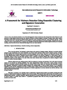
Figure 1.
using the method described in section II. B for computing the
Pt . A indicate the matching images in set 10 camera parameters
J;
,
at
and
2
7°ir=====::;==::;-----i --+- Mosaic enerated by 3 ima es 265 ---e--- Mosaic ggenerated by 11 imagges �260
predication which with frame t can
enable the algorithm to reducing the processing time. After ' camera parameters are computed the frame t is resized to t using the projecting matrix P
The average error of location algorithm(pixels).
E �
255
:
[ltll Itll o
P=
0 o
235 2�,L------� 2�----- �
o
' So the parameters of t is parameter
1 , at
and
number of image sets
Pt . For
' each pixel on t a patch (the same size as chosen in section
Figure 2.
II.B) centered at itself is chosen for computing the HGL, and the pixel location is projected to correct location on the mosaic. Note that, the location on the mosaic may not be integer, and then Bilinear Interpolation Arithmetic is used for computing the HGL of the location. Finally the KL
the image to the mosaic. The average projecting error is defmed as:
200 e=-L�(x-x'Y +(y-y,) 2 200i=1 Where (x,y) is the point location on the mosaic and (X"y,) is the point's, which is the corresponding point on 1
Divergence [17] D of the two HGL is computed, if D is larger than a threshold, the pixel is subject to belong the moving object; otherwise it is subject to be background.
D(P I Q) =.!. ± P;logPi +qilOgiL 2i=1 qi Pi
(
IV.
J
images, projecting location on mosaic. Fig.l shows the average projecting error at different conditions. From the figure we can see the error goes larger when the number of image sets goes larger.
EXPERIMENT
We mainly tested outdoor images for this experiment. A
B.
Core 2 2.66GHz PC and a PTZ camera which provides 352x240 video frames were used. For the same surveillance area, two mosaics are generated. One is generated by 3
Time consumption
For evaluating the time consumption, we compute the average time that spends dealing with one frame. From ig.2 . we can see there is little difference between these conditIons.
�
images and the other one is generated by II images. And the background models are generated by 1, 2, 3 sets of images respectively.
A.
The average time consumption(ns)
For reducing the average time consumption the image size can be resized to 114 of is original size.
C.
Evaluation of the location precision
System result
Fig.4 gives a sequence result of our system. The test frame sequences are capture with different focal ength �d view points. The system can give a good result m locat�g the frame to the correct position to the mosaic and extractmg the moving object. Also the system can give the trace of �he moving object on the mosaic which can be used for domg other research, e.g. event analyze.
For evaluating the location precision, 10 real time frames are chosen and 20 pairs of corresponding points are signed
�
manually on each image and the mosaic. The algorithm described in section III is used for projecting the points on
660
V.
CONCLUSION
We present a framework for PTZ-based surveillance system. The framework is based on background subtraction technique and it allows the system work well when the zoom value changes a lot. But the algorithm is not fast enough to track an object that moves quickly and the background model is not robust because there is so few information that can be used for the background model.
[6]
D. Greenhill, J. Renno, 1. Orwell and G. Jones, "Learning the semantic landscape: embedding scene knowledge in object tracking," Real-Time Imaging, voUI, 2005, pp. 186-203, doi: 10. 10 16/j.rti.2004. 12.002.
[7]
C.C. Chen, Y.Yao, A. Drira, A. Koschan andM. Abidi, "Cooperative mapping of multiple PTZ cameras in automated surveillance systems," IEEE Conference on Computer Vision and Pattern Recognition, IEEE Computer society, June. 2009, pp.l078-1084, doi: 10. 1 109/CVPRW.2009.5206780.
[8]
S. Kang, 1. Paik, A. Koschan, B. Abidi and M. A. Abidi, "Real-time video tracking using PTZ cameras," Proc. of SPIE 6th International Conference on Quality Control by Artificial Vision, SPIE, Oct. 2003, pp. 103- 1 1 1,doi: 10. 1 1 17/ 12.5 14945.
[9]
A. Bevilacqua and P. Azzari, "A Fast and Reliable Image Mosaicing Technique with Application to Wide Area Motion Detection," Image Analysis and Recognition, vol. 4633, 2007, pp.50 1-5 12, doi: 10. 1007/978-3-540-74260-9.
ACKNOWLEDGMENT
This work is supported by the National Natural Science Foundation of China (60903070, 60827003), the Hi-Tech Research and Development Program of China (2007AAOIZ325, 2008AAOIZ303) and the Innovation Team Development Program of the Chinese Ministry of Education (IRT0606).
[ 10] M. Brown and D. G. Lowe, "Automatic panoramic image stitching using invariant features," International Journal of Computer Vision, vol. 74( 1), Aug. 2007,pp. 59-73,doi: 10.I007/sI 1263-006-0002-3.
REFERENCES [I]
[II] M. Brown, and D. G. Lowe, "Recognizing panoramas," International Conference on Computer Vision, IEEE Computer Society, Oct. 2003, pp. 12 18- 1225,doi: 10. 1 109/ICCV.2003.1238630.
M. Piccardi, "Background subtraction techniques: a review," IEEE International Conference on Systems, Man and Cybernetics, IEEE Computer society, Oct. 2004, pp. 3099-3104, doi: 10. 1 109IICSMC.2004. 1400815.
[ 12] D.G. Lowe, "Distinctive image features from scale-invariant keypoints," International Journal of Computer Vision, vol. 60, 2003, pp. 9 1- 1 10, doi: IO.l023/B:VISLOOO0029664.996 15.94.
[2]
M. Lalonde,S. Foucher,L. Gagnon,E. Pronovost,M. Derenne and A. Janelle, "A system to automatically track humans and vehicles with a PTZ camera," Proceedings-SPIE the International Society for Optical Engineering, vol. 6575, May. 2007, pp. 657502. 1-657502.8, doi: 10. 1 1 17/ 12.7 18446.
[3]
C.H. Chen, Y. Yao, D. Page, B.R. Abidi, A. Koschan and M. Abidi, "Heterogeneous Fusion of Omnidirectional and PTZ Cameras for Multiple Object Tracking," IEEE Transactions on Circuits and Systems for Video Technology, vol. 18(8),2008, pp. 1052-1063, doi: 10. 1 109ITCSVT.2008.928223 .
[4]
G. Jones, 1. Renno, and P. Remagnino, "Auto calibration in multiple camera surveillance environments," Proceedings 3rd IEEE Int. Workshop on PETS,IEEE Computer society,2002,pp. 40-47.
[5]
R. Bowden and P. K. T. K. Pong, "Towards automated wide area visual surveillance: tracking objects between spatially separated, uncalibrated views," IEE proceedings. Vision, image and signal processing, voU52(2), April. 2005, pp. 2 14-224, doi: 10. 1049/ip vis:20041233
[ 13] C. Silpa-Anan and R. Hartley, "Optimized KD-trees for fast image descriptor matching," IEEE Conference on Computer Vision and Pattern Recognition,IEEE Computer society, Aug. 2008, pp. 1-8, doi: 10. 1 109/CVPR.2008.4587638 . [ 14] M. A. Fischler and R. C. Bolles, "Random sample consensus: a paradigm for model fitting with applications to image analysis and automated cartography export," Communications of the ACM, vol. 24(6), 198 1,pp. 8 1-395,doi: 10. 1 1451358669.358692. [ 15] P. McLauchlan and A. Jaenicke, "Image mosaicing using sequential bundle adjustment," Image and Vision Computing, vol. 20, Aug. 2002, pp. 75 1-759,doi: 10. 10 16/S0262-8856(02)00064- 1. [ 16] S. Kullback, and R. A. Leibler, "On information and sufficiency," Annals of Mathematical Statistics, vol. 22, 195 1, pp. 79-86, doi: 10. 12 14/aoms/I177729694 [ 17] H. Chui and A .Rangarajan, "A new algorithm for non-rigid point matching," IEEE Conference on ComputerVision and Pattern Recognition, IEEE Computer society, June. 2000, pp. 44-5 1, doi: 10. 1 109/CVPR.2000.854733
Offline phase r---------------,
I Background generatio � I lusing all images L _______
_ _ �e� �-� �m.: J!�m_e _
-7
Camera parameters computing
Inline phase
The overall view of the PTZ-based Surveillance Systems.
661
1
Moving object detecting and location on mosaic
Motion predication and control signal
Figure 3.
______
Figure 4.
The result of the system. The mosaic above is generated by 3 images and the below one is generated by II images.
662