A Cut-through MAC for Multiple Interface, Multiple Channel Wireless Mesh Networks Joo Ghee Lim, Chun Tung Chou, Alfandika Nyandoro and Sanjay Jha School of Computer Science and Engineering University of New South Wales NSW 2052, Australia Email: {jool, ctchou, alfan, sjha}@cse.unsw.edu.au Abstract— A Wireless Mesh Network (WMN) that utilizes multiple interfaces and multiple channels has been shown to improve network performance by reducing the interference and increasing the available bandwidth. However, the contention delay experienced by a frame along every hop of the WMN can still limit the performance. In addition, cross-layer delay occurs when a frame has to travel up and down the protocol stack to access different interfaces. In this paper, we motivate the need for a MAC in a multi-interface backhaul WMN and propose a cutthrough MAC that is able to reduce the end-to-end delay of data frames in the network. Preliminary simulation results show that this MAC scheme gives higher goodput and lower end-toend delay in a chain topology, when compared to IEEE 802.11 DCF MAC. The paper also highlights key challenges that need to be addressed in the design of a cut-through MAC for multihop wireless networks.
I. I NTRODUCTION Most of the current Wireless LAN deployments consist of wireless clients that can only stay connected if they are within the transmission range of an access point (AP). Although roaming is possible in the form of an Extended Service Set (ESS), this often requires the extensive laying of cables to connect the APs.1 Recently, there has been much work done in developing a network of dedicated “AP-like” devices that can relay traffic in a multi-hop manner, known as a Wireless Mesh Network (WMN) [1]. The traffic consists of packets between a pair of clients connected to the WMN, as well as between a client and a host in an external network. Using the IEEE 802.11 Distributed Coordination Function (DCF) [2] as the MAC protocol for wireless multi-hop networks has been shown to result in sub-optimal performance. This is because the broadcast nature of the wireless medium creates inter-flow as well as intra-flow interferences [3]. Solutions to this problem have focused on two main approaches – modifying the MAC layer (e.g. [4], [5]) and increasing the number of interfaces available to mesh routers [6]. When collisions and interference occur, delay is experienced as the frames have to be retransmitted. Essentially, a MAC protocol tries to coordinate the access of the shared channel 1 Although a wireless ESS is possible in the form of Wireless Distribution System (WDS), the solutions are currently proprietary as the specifics have yet to be standardized by IEEE 802.11.
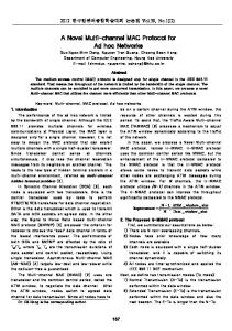
so that multiple transmitters can send frames with minimal delays. To do this, the MAC employs additional mechanisms that trade a slight increase in overheads for a more efficient use of the channel. This constitutes the contention delay experienced by a node in a network. Examples of contention delays include times spent on control messages (e.g. RTS/CTS) and backoffs in contention-based MAC, as well as timing synchronization overheads in TDMA-based MAC. In a multi-hop WMN, a frame experiences this contention delay at every router on its way to the destination or gateway, resulting in an increased end-to-end delay. Introducing multiple wireless interfaces to each mesh router can reduce the number of routers (or interfaces) contending for the same wireless channel. However, each frame entering into the network would still have to contend afresh for the channel at every hop. If the channel could be reserved in advance, this multi-hop contention delay would effectively be reduced. Moreover, multiple interfaces introduce an additional delay when the packets traverse across the different layers of the protocol stack and the different interfaces within each router. In this paper, we term this delay as the cross-layer delay. If not managed efficiently, this could increase the overall delay and reduce the throughput available to the network [7]. A suitable MAC protocol is therefore needed to reduce the multi-hop contention delay and the cross-layer delay. Having motivated the need for a MAC protocol in a multiple interface WMN, we propose a cut-through MAC that seeks to increase the overall network performance. We start by stating some assumptions on our WMN architecture in Section II, before introducing our cut-through MAC in Section III. Section IV contains some initial results from simulations that we have conducted to evaluate our scheme. We highlight the challenges involved in developing a cut-through MAC for multihop wireless networks in Section V. In Section VI, we discuss several related works, followed by some concluding remarks in Section VII. II. A SSUMPTIONS ON WMN A RCHITECTURE Our cut-through MAC scheme is designed specifically for backhaul WMN consisting of mesh routers whose primary role is to forward the network traffic in a fast and efficient manner. Figure 1 shows a setup of such a WMN. Besides the dedicated mesh routers, there are mesh APs providing connections to
wireless clients and mesh gateways with physical connections to external networks. We assume in this paper that the interfaces used for connection of clients are separated from those used for the forwarding of the backhaul traffic.
TABLE I E XAMPLE OF A L ABEL S WITCHING TABLE (LST) INCOMING
OUTGOING
I/F
Label
MAC Addr.
I/F
Label
MAC Addr.
1
Lxy
AA:AA:AA
2
Lwz
CC:CC:CC
...
...
...
...
...
...
3) The channel for each interface has been independently computed and assigned. 4) A layer 2 label switching protocol is in placed. III. C UT- THROUGH MAC
Fig. 1. A typical Wireless Mesh Network setup with mesh routers (MR), mesh access points (MAP) and mesh gateways (MG).
In backhaul WMN, it makes sense to aggregate the traffic from different clients together if they are bound for the same destination. Even when the final destinations are not the same, e.g. different hosts on the other side of the Internet, there is still a common destination as far as the WMN is concerned – a mesh gateway. Traffic aggregation helps to efficiently transport the packets over the network. A common way of doing aggregation is to use a MPLS[8]-like scheme that “groups” packets destined for the same egress gateway using a label that identifies them at layer 2. Distinguishing packets with such labels within the WMN has the added advantage of reducing the cross-layer delay since the packets do not have to move up to the network layer and down again. It has been shown that this delay can take up to 60% of the processing delay in a networking device [7]. The details of such a scheme are outside the scope of this paper 2 . We assume that such a scheme is implemented in the WMN, allowing a mesh router to mark the MAC frame with a particular label, and forward the frame using the right interface at layer 2. Table I shows a typical Label Switching Table (LST) that would be present in a mesh router with such a capability. In the example, an incoming frame on interface 1 tagged with label Lxy will be transferred to interface 2 and tagged with a label of Lwz. In this way, an intermediate mesh router does not have to look at the network layer packet header to determine the next hop. This paper makes the following assumptions on the WMN architecture that is suitable for applying our MAC scheme: 1) The mesh routers are static. 2) Each mesh router can have multiple interfaces (≥ 1). 2 The reader is referred to the vast literature on MPLS for details on such label switching schemes, and the propagation of the label information.
In this section, we describe the Multiple Interface Advance Channel Reservation (MIACR) protocol, a cut-through MAC that allows a MAC frame to traverse over multiple hops with minimum delay. The main aim of MIACR is to reduce the delay a frame experienced in each multi-interface mesh router. The label switching mechanism discussed above helps to reduce the cross-layer delay within a mesh router. To reduce the multi-hop contention delay, MIACR introduces the concept of advance collision avoidance by reserving the channel on the next interface in advance. To describe the operation of MIACR, we will first introduce the control frames required, a channel state table that a mesh router maintains for each interface, followed by an example on how they would be used to reserve the channel in advance. A. Control Frames The control frames in MIACR serve similar functions as those in IEEE 802.11 DCF – to acquire the channel for the collision-free transmission of the data frames, and to inform neighboring nodes of this acquisition. The main difference is the ability to make advance reservation of the wireless medium. Channel Reservation Request (CRRQ): This acts like the RTS in IEEE 802.11 DCF. In addition to the fields found in RTS, the CRRQ includes the label (l), the reservation id (idr ), the reservation time (tr ) and the reservation duration (dr ). It is worth noting here that tr is the offset time after the CRRQ is received at the receiver. This way of representing the time of an action is similar to the duration field in RTS/CTS frame that is used to calculate the Network Allocation Vector (NAV). The rest of the fields will be explained in the example below. Channel Reservation Reply (CRRP): This acts like the CTS in IEEE 802.11 DCF. Similar to CRRQ, it contains l, idr , tr and dr , in addition to the CTS fields. Note that the reservation time and duration represented by tr and/or dr in the CRRP may be different from that requested by the CRRQ. This happens when the receiver proposes another reservation time and/or duration. Channel Reservation Confirm (CRCF): When the replied reservation time and/or duration is different, the requesting router must confirm with a CRCF to agree or cancel the reservation. This contains the updated tr , dr and a reservation cancel flag set if the reservation is to be cancelled.
TABLE II E XAMPLE OF A C HANNEL S TATE TABLE (CST)
����
� Channel x
����
������
� �
����
Channel y
Time Occupied
Duration
Time Occupied
Duration
τr1
tdata1
τr2
tdata2
...
...
...
...
��
�
���
� �
�
�
� ���
����
�
��
Fig. 2. A topology for the example. The gateway, GW has a wireless interface and a physical connection to a wired network.
����
���
����
τ��
�����������
�� �� �
τ��
�����������
Fig. 3. Timing diagram of the interaction between the interfaces of A, B and C. Each side of the horizontal line represents an interface of a node, e.g. the top side of the second line represents Interface IF1 of node B (communicating with Interface IF1 of A) and the bottom side represents Interface IF2 of node B. τx represents actual timings and tx represents relative offset times. ����
Similar to the RTS/CTS/Data/ACK operation in IEEE 802.11 DCF, the CRRQ/CRRP/[CRCF]3 operation in MIACR is a contiguous series of frames with a short interframe space (SIFS) separating them.
�
�
τ�
����������
���
� �
� �
���
���� �
� �
� �
���
�� ��
�
���
�� �
�
� ��
� ������������������ � ��
�
����� ��������������������
����
�����������
����
B. Channel State Table Each router maintains a channel state table (CST) for each of its interfaces. The CST contains the reservation information of the channel the interface is on. From the control frames received, a router will update the CST with the time and duration the channel will be busy because of a successful reservation, either by its upstream router, or by a neighboring router using the same channel. Table II shows an example of a CST. C. Operating Example In this section, we provide an example of how advance reservation can be done in MIACR to achieve cut-through. Figure 2 shows the topology of a chain WMN used in this example. In this example, mesh router A needs to send traffic to the Internet via the gateway GW . On looking up its LST, it finds that it must send the data frames to router B using interface IF1, which is on channel CH1. A sends a CRRQ to B’s interface IF1 requesting for channel time tr1 after the CRRQ frame, for a duration of tdata1 . Router B, on receiving the CRRQ, computes the actual reservation time requested by adding the offset tr1 to its actual clock time and checks its CST to ensure that channel CH1 is not occupied at that time. It updates the CST with this reservation accordingly and sends back to A a CRRP with the channel time of t�r1 after the CRRP frame. From the label contained in the CRRQ, B knows that this data from A is bound for GW . Checking its own LST shows that the data should be forwarded to router C on channel CH2 using IF2. Even while the transmission of the data on channel CH1 is going on, B can begin to reserve the channel CH2 by sending a CRRQ to C. The time requested for reserving channel CH2 should be as close as possible to the completion of the transmission of the data in channel CH1. Ideally, upon 3 The CRCF frame is optional since it is only required if the reservation request had been changed by the receiver.
Fig. 4. Timing diagram of the interaction between router C and D. Since part of the requested time has been reserved, D propose a new reservation time, which is accepted by C.
receiving the data on IF1, it could be switched onto IF2 for transmission after a short processing delay, tproc . tproc is the time needed to process the data at layer 2, including changing the header information and transferring the data from one interface to the next. As discussed in Section II, tproc is typically less compared to when layer 3 routing is used. Figure 3 shows the timing diagram for the reservation of channel CH1 between A and B and CH2 between B and C. There might be situations when the channel/time requested has been reserved for another transmission. For example, when the CRRQ from router C reaches router D, the CST of D’s IF1 indicates that a prior reservation overlaps with the requested time. The new request would not be accepted as it would disrupt the existing reservation. Hence, router D will reply with a CRRP containing a proposed new reservation (offset) time of t�r3 . If this new reservation time is acceptable to C, it will send a CRCF with the new adjusted time. Otherwise, it will send a CRCF with reservation cancel flag set. Figure 4 shows the timing diagram of such an interaction. D. Key Features and Salient Points As the full details of MIACR could not be included in this paper due to space constraints, we will highlight some key features and salient points of the protocol here. 1) MIACR makes use of IEEE 802.11 PHY as its physical layer. Modification is performed on the MAC layer in terms of the operation and frame formats. This allows the possibility of implementing the scheme on platforms like SoftMAC [9]. 2) The broadcast nature of the control frames allows neighboring routers with interfaces on the same channel to be
aware of the reservations. This is also the reason why a CRCF frame has to be sent if there are any changes to the original reservation request. Similar to the RTS/CTS mechanism in IEEE 802.11 DCF, this reduces the effects of the (in)famous hidden-node problem. For example, in Figure 4, the pre-existing reservation may not involve D, but two other neighbors that could interfere with any communication with D. 3) The reservation scheme in MIACR uses offset timing derived from the instance when the frame is received at the receiver. This removes the necessity of global clock synchronization, a challenging issue in reservation protocols. However, some timing allowances have to be factored into the offset to account for the propagation delay of the frames to nodes at different distances from the transmitted. 4) MIACR tries to reserve the channel of the next hop (on the next interface) in advance to minimize the delay a data frame encounters within each hop. A key parameter is the time between the reception of a CRRP on one interface and the transmitting of CRRQ on the next interface, represented by tresp1 and tresp2 in Figure 3. A delay that causes the next-hop CRRQ to be sent after the complete reception of the data frame will approach the performance of IEEE 802.11 DCF, while too small a value (e.g. if IF1 of C sends out CRRQ before τr2 ) runs the risk of reservation wastage if the previous hop data transmission had not taken place as planned. We plan investigate the effects this delay as part of our future work. In this paper, we assume tresp = 0. 5) Within a reservation duration, the transmitter could potentially send out more than one data frame. This will further decrease the delay as the overheads associated with each transmission are reduced. Issues like fairness and acknowledgement granularity (i.e. to acknowledge after each frame or each reservation duration) would have to be investigated. In this paper, we assume each reservation contains one data frame. IV. S IMULATION R ESULTS In this section, we describe preliminary results of simulation experiments conducted to analyze the performance of MIACR. The topology used in the simulation is a chain topology with number of nodes N varying from 3 (2 hops), to 7 (6 hops). The first and last nodes of the chain have a single wireless interface and the intermediate nodes contain two wireless interfaces. We contend that this simple network layout will provide some insights into the performance of the scheme without the influence of other issues on more complex topologies, e.g. the effects of different channel assignments. We assume the number of non-overlapping channels is limited to three – a valid scenario applicable to the popular IEEE 802.11b/g standards. In our experiments, we assume that the channels have been a priori assigned to each interface. The optimum channel assignment in a chain topology would then be assigning channel 1 to the link between the first node and
TABLE III R ELEVANT S IMULATION PARAMETERS Simulation Time Application Traffic PHY Data Rate PHY Tx Power PHY Rx Sensitivity Approx Tx Range Propagation Pathloss Model Inter-nodal Distance
600s (10mins) Constant Bit Rate (CBR) UDP 11 Mb/s 15dBm -83dBm 283.554m Two-Ray 250m
one interface of the second node, channel 2 to the link between the second interface of the second node and the first interface of the third node, and so on. The sequence is repeated once the total number of available non-overlapping channels has been assigned. Figure 2 represents an instantiation of such a channel assignment with N = 5. We implemented MIACR on the QualNet network simulator [10] and compared it with the IEEE 802.11 DCF MAC protocol, both using the IEEE 802.11b PHY layer. Besides providing a realistic lower layer platform (including propagation, interference and error models), this allows us to focus on the comparison and analysis of the MAC performance. Table III shows the relevant simulation parameters used. Traffic is injected at the source at one end of the chain, bound for the destination at the other end. This is like aggregated traffic from a mesh access point (source) travelling over one or more mesh routers to a mesh gateway (destination) that is connected to the Internet. The metrics compared are the goodput – the application layer throughput achieved by the CBR traffic, and the end-toend delay – average delay experienced by the application layer packets between the source and destination. In each simulation scenario, 10 trials were performed with the metrics averaged over these trials. Figure 5 shows the goodput and end-to-end delay experienced by the CBR traffic for a chain topology with 6 wireless links. In this layout, it should be noted that each non-overlapping channel is reused once. We see that the endto-end delay of the packets is less in MIACR compared to IEEE 802.11 DCF. The advance reservation allows each frame to spend less time in the network. This also enables the network to sustain a higher overall goodput (the networksaturation goodput). This can be seen from the goodput performance – as we increase the offered load, the networksaturation goodput is higher for MIACR. This is because getting the frames through the network as fast as possible allows the channel to be free more often, thereby increasing the opportunities that a new frame could be transmitted. It should also be noted that the end-to-end delay of interest is during the non-saturated condition, i.e. below 3 Mb/s offered load in MIACR and 2 Mb/s offered load in IEEE 802.11 DCF. During network saturation, the high delay would likely render the application layer packets useless at their destination. This is especially the case in real-time traffic where certain delay bound has to be kept and in TCP/HTTP traffic where timeout occurs after excessive delays. In Figure 5, we see that besides
this section, we highlight some of the key challenges faced when developing a cut-through MAC. A. Hidden Node Problem
Fig. 5. Goodput and end-to-end delay for different offered loads in a 6-link chain topology.
(a) Network saturation goodput
(b) Non-saturated end-to-end delay
Fig. 6. Network saturation goodput and non-saturated end-to-end delay for different chain lengths.
achieving a lower end-to-end delay, MIACR allows a higher offered load to be transmitted before this high saturation delay occurs. We next studied the performance of MIACR when compared to IEEE 802.11 DCF for different chain lengths. Figure 6(a) shows the network-saturation goodput for chains of different lengths (hops). We can see that there is little difference in the goodput when there are enough non-overlapping channels. This is because under network saturated condition, MIACR performs in a similar manner to DCF, with no advance reservation possible. The slightly lower goodput is a result of the extra overhead used in MIACR. However, once the channels are reused, MIACR performs much better than DCF. Here, the channel reservation allows for a more efficient management of the channel collision space, which accounts for the better performance. Figure 6(b) shows the non-saturated end-to-end delay. The average end-to-end delay experienced is lower for MIACR and the performance is improved for higher length chains. Thus MIACR allows the frame to spend less time in the chain network due to cut-through. V. C HALLENGES OF C UT-T HROUGH MAC While a cut-through MAC protocol has the potential to improve the performance of multihop wireless networks like WMN [4], [11], [12], challenges are still present, especially when extending it to WMN utilizing multiple interfaces. In
The hidden node problem typically occurs when the interference range of a node’s transmission is larger than its communication range, i.e. the distance within which the signal can be correctly decoded. In IEEE 802.11 DCF, this problem is only partially alleviated using the RTS/CTS mechanism [3]. When advance reservation is used in cut-through MAC, a neighboring node that did not receive the reservation frame and transmits a frame during the reserved time could disrupt the data communication. This occurs when the node is out of the communication range of the node making the reservation, but is still within the interference range of the reservation. As discussed above, the CRRQ/CRRP/[CRCF] handshake in MIACR tries to reduce this hidden node problem, similar to the RTS/CTS mechanism. A way to further limit the effects of hidden nodes in cutthrough MAC is to set aside a separate, orthogonal control channel for reservation purposes. Reservation frames sent over this channel should be of higher transmit power so that they could be heard by all the nodes within the interference range. This channel can be of a narrower bandwidth in order to conserve the valuable channel resources. In [13], Acharya et al propose another way to reduce this problem, by using an adaptive learning mechanism. B. Traffic Dependency Cut-through MAC attempts to reduce the time spent by a frame when contending for the channel along each hop in its path to the destination. This works well under low/medium network traffic load. However, as shown by the simulation results, there is little gain in doing advance reservation when the network becomes saturated, since the frames are being sent back-to-back. In fact, advance reservation requires additional overheads (e.g. longer headers) than IEEE 802.11 DCF, which may lead to under-performance when the network is overloaded. This observation points to the conclusion that cut-through mechanism should not be used for all traffic types. It opens the possibility of a MAC protocol that performs advance reservation for high priority, non-elastic traffic to achieve cutthrough, with per-hop RTS/CTS-like channel contention for low priority, best effort traffic. An alternative way to adapt cut-through MAC for higher traffic load is to provide reservation for multiple frames when the traffic is bursty. Some commercial Wireless LAN chipsets [14] already implement a similar idea that allows the transmission of more than one data frame within a transmission opportunity. It should however be noted that multiframe reservation requires the frames to be buffered in the source node as the reservation is being set up. This may lead to a higher latency for some of the frames, countering the advantage of cut-through.
C. Frame Loss Management In cut-through MAC, reservation is done for the transmission duration of a data frame, potentially for several hops forward. If the data frame is lost in an upstream hop, subsequent downstream reservations will not be utilized, and the channel is left idle. This is expensive in terms of the channel resources, which could be otherwise used to transmit frames from neighboring nodes. There is therefore a need to have a mechanism to free the reservations over the hops in the forwarding path. D. Timing Synchronization In doing reservation over multiple hops, timing synchronization among the nodes is a critical issue. Global timing synchronization is often difficult, if not impossible, due to clock drifts within each node. The challenge is to develop an efficient synchronization mechanism that can allow reservations over multiple hops to take place. In MIACR, we propose a relative synchronization approach that is similar to the way the duration field in IEEE 802.11 DCF is set. E. Fairness Issues Finally, fairness is a key challenge when we allow a frame to have access over multiple hops of a forwarding path. Admittedly, we have not addressed nor investigated the issue of fairness in the MAC proposed in this paper. As part of our subsequent work, we plan to look at this issue and propose ways to maintain a level of fairness in cut-through MAC. VI. R ELATED W ORK In [15], Acharya et al describe an architecture incorporating MPLS with an enhanced IEEE 802.11 DCF MAC where the RTS frame for the next hop is transmitted concurrently with the Ack frame of the previous hop. This reduces the time a frame needs to spend in a node due to channel contention. Similar cut-through schemes have also been proposed by [11] and [12]. These approaches have applications to a single channel network environment, while MIACR is specifically designed to perform cut-through in a multiple interface, multiple channel network. In addition, MIACR also provides an advance reservation mechanism that is able to extend beyond the immediate next hop. Carlson et al [16] present a distributed reservation protocol to support real-time services in WMN. In their approach, they assume all the routers have global synchronized timings. MIACR’s reservation scheme makes use of relative offset timings to set up advance reservation. The reservation protocol in [16] also does not take into account multiple interfaces and channels. VII. C ONCLUSION In this paper, we motivate the need for a cut-through MAC protocol in a WMN with multiple interfaces and multiple channels. MIACR, a cut-through MAC suited for this type of application is proposed. The cut-through mechanism makes use of advance channel reservation on different interfaces in
forward hops to reduce the delay a frame encounters in its passage through the network. We include preliminary results of simulations that we performed to evaluate the effectiveness of our scheme, comparing it to the incumbent IEEE 802.11 DCF MAC in a simple chain topology with CBR traffic. We plan to extend this investigation to more complex network setups as well as realistic traffic types. We also plan to analyze the effects of various parameters that may affect the performance of our scheme, e.g. the time to activate the next hop reservation (tresp ) and the number of frames to transmit in each reservation. Issues like how fairness can be maintained in such a scheme will also be studied. ACKNOWLEDGMENT The support of the Co-operative Research Centre for Smart Internet Technology (http://www.smartinternet.com.au) for this work is hereby acknowledged. The authors would also like to thank Dr. Archan Misra for his valuable comments. R EFERENCES [1] I. F. Akyildiz, X. Wang, and W. Wang, “Wireless Mesh Networks: a Survey,” Computer Networks Journal (Elsevier), vol. 47, no. 4, pp. 445– 487, March 2005. [2] IEEE, Part 11: Wireless LAN Medium Access Control (MAC) and Physical Layer (PHY) Specifications, Std. 802.11-1999, August 1999. [3] K. Xu, M. Gerla, and S. Bae, “Effectiveness of RTS/CTS Handshake in IEEE 802.11 based Ad Hoc Networks,” Ad Hoc Networks, vol. 1, no. 1, pp. 107–123, 2003. [4] A. Acharya, A. Misra, and S. Bansal, “MACA-P: A MAC for Concurrent Transmissions in Multi-Hop Wireless Networks,” in IEEE PerCom 2003, Texas, USA, March 2003. [5] X. Yang and N. H. Vaidya, “A Wireless MAC Protocol Using Implicit Pipelining,” IEEE Trans on Mobile Computing, vol. 5, no. 3, pp. 258– 273, 2006. [6] A. Raniwala and T. Chiueh, “Architecture and Algorithms for an IEEE 802.11-based Multi-channel Wireless Mesh Network,” in IEEE Infocom 2005, Miami, USA, March 2005. [7] W. Kampichler and K. M. Goeschka, “On Measuring Quality of Service Limitations in Local Area Networks,” in IEEE ICC 2003, vol. 1, Anchorage, USA, May 2003. [8] E. Rosen, A. Viswanathan, and R. Callon, “Multiprotocol Label Switching Architecture,” IETF RFC 3031, 2001. [9] M. Neufeld, J. Fifield, C. Doerr, A. Sheth, and D. Grunwald, “SoftMAC Flexible Wireless Research Platform,” in Fourth Workshop on Hot Topics in Networks (HotNets), Maryland, USA, November 2005. [10] QualNet Network Simulator. [Online]. Available: http://www. scalable-networks.com [11] D. Raguin, M. Kubisch, H. Karl, and A. Wolisz, “Queue-driven Cutthrough Medium Access in Wireless Ad Hoc Networks,” in IEEE WCNC 2004, Atlanta, USA, March 2004. [12] G. R. Hiertz, J. Habetha, E. Weiss, and S. Mangold, “A Cut-through Switching Technology for IEEE 802.11,” in IEEE Circuits and Systems Symposium on Emerging Technologies, vol. 3, Shanghai, China, May 2004. [13] A. Acharya, A. Misra, and S. Bansal, “Design and Analysis of a Cooperative Medium Access Scheme for Wireless Mesh Networks,” in First International Conference on Broadband Networks (Broadnets’04), San Jos´e, USA, October 2004. [14] Atheros Communications. (2004) “Super G: Maximizing Wireless Performance”. White Paper. [Online]. Available: http://www.atheros. com/pt/whitepapers/atheros superg whitepaper.pdf [15] A. Acharya, A. Misra, and S. Bansal, “High-Performance Architectures for IP-based Multihop 802.11 Networks,” IEEE Wireless Communications, vol. 10, no. 5, pp. 22–28, 2003. [16] E. Carlson, C. Prehofer, C. Bettstetter, H. Karl, and A. Wolisz, “A Distributed End-to-End Reservation Protocol for IEEE 802.11-based Wireless Mesh Networks,” IEEE Journal on Selected Areas in Communications, vol. 24, no. 11, pp. 2018–2027, November 2006.