A 3D Shape Measurement System Zhifu You1 Charles L. Thomas1 Robert F. Erbacher2 1
Mechanical Engineering Dept, University of Utah, Salt Lake City, UT 2 Computer Science Dept, Utah State University, Logan, UT
Abstract This paper presents a 3D shape measurement system for stationary objects which features reduced cost, high accuracy, and ease of implementation. An integral part of this system is a 2D multi-plane camera calibration technique, implemented with improvements to the automation and corner extraction over traditional techniques. A binary coded structured light plus phase shifting technique is implemented in which a modified sequence is employed to solve the correspondence problem. The modified sequence is more sensitive to shape changing than traditional sequence. A simulated annealing algorithm is used to find the best sequences. A phase value based correction technique is applied to retrieve relatively reliable codewords. The phase shifting technique is also used to obtain higher resolution results. Final results show that this modified binary code light strategy has higher accuracy than traditional ones. Keywords: coded structured light, phase shifting, modified sequences
1. Introduction 3D reconstruction has been a hot topic in the computer vision community for decades due to its wide field of application. With the technical advancement of manufacturing and industrial design, the measurement of geometrical surface parameters such as distances, heights, or 3D coordinates now plays a critical role in design, inspection, and quality control. Implementation of such measurement capabilities requires solutions to two primary problems, namely: calibration and correspondence. Triangulation is a commonly used technique to calculate coordinate positions and it is possible if and only if calibrated cameras are available [1]. Camera calibration is the process of determining camera system external geometry (the relative position and orientation of each camera) and internal geometry (focal length, optical center, principle point, lens distortion, and scale ratio). An accurate estimate of these geometries is necessary in order to relate image information (expressed in
pixels) to an external world coordinate system. Currently, the problem of camera calibration is wellunderstood and high-quality toolkits are available [2]. However, improvement in the flexibility of such existing toolkits is needed. Additionally, finding the correspondence points between 2D images is another problem that has yet to be solved in a generalized and effective paradigm. The correspondence problem consists of determining the location in each camera image that is the projection of the same physical point in space. It turns out to be a very difficult problem due to the ambiguities and illposed conditions. More specifically, there are ambiguities in the relation of the 2D images as they are derived from a 3D image from different points of view. In addition, noise and occlusion confound the correspondence problem, causing it to be ill-posed. While solutions to the correspondence problem do exist, they have limitations. More specifically, studies on the different solutions have shown that all available strategies have advantages and disadvantages [3, 4]. Coded structured light is considered to be one of the most reliable techniques for solving the correspondence problem [1]. It is inexpensive, easyto-implement, and highly accurate. Its primary drawback is the need for a sequence of images, rather than a single image. Additionally, this technique is limited due to its low sensitivity to changing shapes. Zhang [5] proposed a modified algorithm to overcome this disadvantage but this modified algorithm has not been applied to the measurement of stationary 3D shapes. In this paper, we employ Zhang’s modified algorithm through the application of simulated annealing. We have developed a phase-based codeword value correction technique to improve on the unsatisfactory results intrinsic to binary thresholding. We are still limited to obtaining the codeword from the strip images; however, the use of the phase value better tunes the codeword. The phase values improve the results by providing robust edge indicators. This greatly improves the codeword values and thus the final result. Our system has been designed around two common electronic devices: video projectors and digital still cameras. A video projector is used to
project a structured light pattern onto the object to be scanned. Two digital still cameras are used to acquire images of the object under the structured lighting. All of the devices are driven by software running on a standard PC. A limitation of this system, common to all structured light techniques, is that the scene must be static during the acquisition period. The rest of the paper is organized as follows. Section 2 introduces the camera calibration results. In section 3, we describe the experiments performed and analyze the experimental results. Section 4 provides the conclusions and future work.
2. Camera Calibration Camera calibration is the first step in the 3D shape measurement process. The 2D calibration technique [6] was chosen for this study to build our 3D shape measurement system since it is easy to implement and achieves very good accuracy with general purpose scanners. This technique requires that more than three images of the planar pattern be observed from different viewpoints. The pattern used here is a simple checkerboard with known width and height. It can be printed by a standard laser printer. A widely popular camera calibration toolkit has been developed by Bouguet [2], which is based on the 2D calibration technique by Zhang [6]. This toolkit is written for Matlab and takes advantage of Matlab’s computational capability. The toolkits disadvantage is that it operates completely off-line and thus doesn’t have a graphical user interface. This means that if the result is unacceptable then the user must redo the entire calibration process. Another disadvantage is that it requires that corner extraction be performed manually, which is inefficient and inflexible. In this paper a completely automatic corner extraction is implemented to improve the efficiency and effectiveness of the calibration toolkit. This is done by using a free online resource called OpenCV [7], which provides a function to locate some of the corners. Additionally, a new algorithm is proposed to recognize the remainder of the corners from the preliminary results provided by OpenCV. The calibration equipment includes: the two cameras to be calibrated, a checkerboard, and a computer. When doing the calibration, one individual must hold the checkerboard in front of the cameras and slowly move it. The goal is to fill the entire viewable area within the camera frames with all four corners of the checker board visible by each camera. This calibration process provides accuracy in the sub-pixel range (standard deviation errors are 0.13 and 0.11 pixel) for a single camera. The stereo calibration provides result with an average error of ~2.04 mm and
a mean relative error of only ~0.14 mm. These results are impressive for a COTS solution to the calibration problem. Recovering epipolar geometry is another important aspect of camera calibration. Given the above results, an essential matrix can be formed which may fully describe this relationship. The epipolar lines can simplify the correspondence problems by restricting the 2D searching into 1D searching [8].
3. Experiments and Results As discussed previously, time multiplexing, structured light techniques have the advantages of low-cost, high accuracy, and ease of implementation. In this paper, the binary coded light technique is used to solve the correspondence problem for the 3D shape measurement system. The phase shifting technique is also applied to produce robust, high-resolution results. The coded light is a sequence of patterns projected onto the surface of the object to be measured. The sequence of patterns carries predefined information and the object’s surface is encoded by the projected patterns. If the object is observed by two cameras from different orientations, the unique code values can be used to identify the corresponding points between these two views. The binary code means that there are only two gray levels within the pattern. Due to its nature, n binary coded patterns can identify 2n regions. Technically the stripe on a pattern can not be made as small as a single pixel, thus the phase shifting technique is needed to extract the sub-region information to achieve pixel-level resolution. Another advantage of using phase-shifting is to help identify the edges of the object since the patterns can be distorted at these edges and make the object boundary difficult to detect. Phase shifting is performed by projecting a sequence of images with a characteristic illumination following a sinusoidal wave pattern. The images differ in the period of the sinusoidal wave employed. The phase values are then calculated by the simple formula given in [1]. This technique can uniquely identify pixels within an identified region with the binary coded light technique. Traditional binary coded light patterns are constructed by recursively dividing a region into half white and half black. Zhang [51] discussed a strategy to modify the traditional binary coded light technique. This modified technique is obtained by shuffling the distribution of coded light in each column to get the greatest number of stripes for all patterns. While this modification can not increase the number of identified regions, it does increase the total number of stripes.
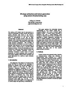
This increase in the number of stripes will increase the pattern frequency. Therefore, the modified technique is more sensitive to changes in surface shape. In this research, a simulated annealing algorithm was employed to find the best shuffling solution in term of the maximum frequency for all patterns. This optimization, applied to 5 image sequences, results in 136 stripes out of a possible 160. In contrast, the traditional scheme results in 31 strips total. The basic idea here is that when given 5 image sequences, we can define 2^5 =32 regions, i.e., for 5 images per sequence there are 5*32 =160 possible regions. This is in contrast to the traditional scheme in which there can be 1, 2, 4, 8, or 16 possible regions. This greatly enhances the feasibility of the algorithm. A statue of Santa Clause (Fig.1) was chosen as the object to work with. The statue is made of plaster and thus has favorable optical properties, including: diffuse reflectivity, white coloring, and non-simplistic features.
interaction to determine the optimal threshold value for each image experimentally. The resulting codeword is displayed in figure 2, and the 3D measurement results are shown in figure 3. We can see that the 3D measurement result contains many bad regions (black holes). This results from the fact that for the modified sequences, the changes in grey level often occur at the same location. The problematic locations for thresholding are the borders where the illumination changes. This causes the modified pattern (i.e., the image sequences with additional strips) to compound the problem by tying the boundary conditions, resulting in significant image degradation. It is not possible to deal with this issue of the modified technique within the thresholding algorithm alone. Additional information must be used in conjunction with the thresholding technique to retrieve the binary code values.
Figure 2. Codeword values before correction Figure 1. Santa’s statue
After capturing all necessary images, the next step is the calculation of the codeword and phase values from said images. It is trivial to retrieve the codeword values from the gray level color images since the coded images were constructed in the binary scheme discussed previously. The difficulty is that there is no perfect image threshold algorithm. There are two types of image threshold algorithms: single value threshold and adaptive threshold. After doing some tests, we found that the adaptive threshold technique is sensitive to local variation of grey level intensity values and thus is not suitable for large region thresholds as is the case here. In this work, a single value threshold algorithm was used in conjunction with user
In this research, a correction technique was developed to correct the bad codeword retrieval results from the threshold algorithm by using the unique information provided by the phase values. This algorithms progresses as follows: 1. Remove noise from the phase value data using neighborhood values. 2. Define the codeword regions using the phase value and maintaining mono-increasing phase values within each region. 3. Validate region integrity by analyzing phase value slope. 4. Identify and remove duplicated codeword values. 5. Recover missing regions through analysis of region relationships, focusing on adjacent regions.
where the result of the modified technique is better than the traditional techniques, such as around the mouth and right hand of the Santa statue. Since the modified technique uses higher spatial frequency and a more balanced illumination across the whole image, it is not surprising that its result is better.
Figure 3. 3D reconstruction result before correction
After the codeword correction, a better result is obtained, as shown in figures 4 and 5. We can see that the correction technique using the phase value information improves the retrieval for the modified technique to a great extent. The identification using phase values are more robust in determination of the codeword values.
Figure 4. Codeword values after correction By comparing these results with the results from traditional binary coded light techniques (Figure 6), we can see that the modified technique produces some improvement on the detailed features, although the general results from the traditional and modified techniques appear similar. We can find several areas
Figure 5. 3D reconstruction result after correction by the modified patterns
Figure 6. 3D reconstruction result by the traditional patterns In figure 5, however, some minor artifacts from both traditional and modified techniques are apparent. The real 3D shape could not be reconstructed in these areas due to the shadows on the source images.
The accuracy of the 3D shape measurement depends on a number of factors: the optical quality of the projector (scene depth and lens quality), the quality of the cameras (resolution, lens radial distortion), the configuration of the cameras and projector (angles between them and baseline, usually long baselines result in better precision but at the cost of a decrease in the viewable area), and the reflective properties of the scanned surfaces (specular surfaces should avoid). Therefore, evaluating the accuracy empirically is not easy. In most cases, the camera calibration accuracy determines the final accuracy. As discussed in section 3, the standard deviation error of the camera calibration is 0.13 mm, so the accuracy of the final 3D reconstruction is better than 1 mm.
[3]
[4] [5] [6]
[7]
4. Conclusion and Future Works A modified binary coded light technique was employed to generate improved results over traditional binary coded light techniques. Additionally, a phase shifting technique was employed to improve the 3D reconstruction in two ways: 1) obtaining a higher resolution result by identifying the pixels inside a region defined by the binary coded light technique; 2) obtaining a more accurate result by providing unique information into a new codeword retrieval correction technique. The phase values are very helpful in the correspondence-solving process. We validated that the phase-shifting technique can be applied to many other 3D reconstruction techniques in order to improve their results. Experimental results from a 3D object verified that the modified binary coded light technique performs worse than the traditional technique if the phase value based correction is not applied. After using this phase value correction during the codeword retrieval, it was shown that the modified technique produces a better result by reducing the artifacts imposed by the traditional techniques on detailed features. Finally, we verified that the combination of the modified binary coded light technique and the phase shifting technique is very effective for solving the 3D construction problem.
5. References [1]
[2]
J. Salvi, J. Pages, and J. Batlle, Pattern codification strategies in structured light systems, Pattern Recognition, Vol. 37, No. 4, pp. 827-849, April 2004. J.-Y. Bouguet, Camera Calibration Toolbox for Matlab, http://www.vision.caltech.edu/bouguetj/calib_do c/
[8]
O. Hall-Holt and S. Rusinkiewicz, Strip boundary codes for real-time structured-light range scanning of moving objects, In Eighth IEEE International Conference on Computer Vision, vol. II, pp.359-366, 2001. S. Rusinkiewicz, O. Hall-Holt, and M. Levoy, Real-time 3D model acquisition, SIGGRAPH, pp. 438-446, 2002. L. Zhang, B. Curless and S. M. Seitz. Spacetime stereo: shape recovery for dynamic scenes. In CVPR, 2003 Z. Zhang, A flexible new technique for camera calibration, IEEE transactions on pattern recognition and machine intelligence, Vol. 22, N0. 11, pp. 1330-1334, Nov 2000. OpenCV from Intel. Inc. http://www.intel.com/research/mrl/research/open cv/overview.htm Q.-T. Luong and O. Faugeras, The Fundamental matrix: theory, algorithms, and stability analysis, The International Journal of Computer Vision, 1(17):43–76, 1996.