www.redpel.com +917620593389
Wireless System for Monitoring and Real-Time Classification of Functional Activity Pankil M. Butala, Yuting Zhang, Thomas D. C. Little Department of Electrical and Computer Engineering Boston University Boston, USA
[email protected],
[email protected],
[email protected] Abstract—The ubiquity of smartphones and their capability to support complex data collection, processing and communications applications is leading to a revolution in personal healthcare. Always ‘on’ and carried, and seamlessly connected to multiple network technologies such as WiFi, Bluetooth, and cellular carrier, these devices can be adopted as hub for aggregating data sourced from custom body-worn sensors. To be effective, however, these devices must balance the diverse design specifications for intermittent smart phone use with the real-time characteristic of health monitoring telemetry. In this paper we focus on the development of sensing devices supporting in-home and community-based health monitoring. We describe the design of a low powered, compact, wireless, and customizable platform for wearable activity monitoring. Of particular importance in this design is the ability to achieve sufficient spatial and temporal sampling resolution for the activity detection mission while meeting battery size and longevity constraints. The sensor design is paired with data aggregation using a WPAN and smartphone to support a body worn network capable of interaction with local telemetry to provide continuous functional activity monitoring, real time activity classification, and notification. Predicted and measured performance data indicate satisfaction of the mission with huge potential gains after optimization of sampling strategies. Keywords- Patient monitoring, accelerometers, wearable sensors, gyroscopes, body sensor networks.
I.
INTRODUCTION
As health awareness increases in society and technology continues to push its boundaries, there is an increasing demand for medical devices that provide around the clock assessment of a subject’s general well being. These self monitoring devices have the potential to dramatically improve a person’s health and productivity; thus improving the individual’s quality of life [1]. Imagine a smart environment enabled with pervasive devices capable of interacting with various types of mobile devices (Fig. 1). One class of these sensors can be body-worn for sensing EKG, pulse, blood oxygen, blood glucose, temperature, gait, limb movement, etc. Continuous monitoring of these parameters is of immense value for patient and fitness characterization, preventative and recuperative feedback, emergency dissemination, and gaming. Data streamed from
Robert C. Wagenaar Department of Physical Therapy and Athletic Engineering Boston University Boston, USA
[email protected]
sensors can be processed locally on a mobile device for rapid detection of events in real time; anomalies and outliers can then be sent over the Internet to a central monitoring station in ‘the cloud’ that is supervised by a healthcare professional. This form of telemedicine is the next generation of personal home healthcare delivery. One application area for this technology is in monitoring the activity of elderly, especially patients with Parkinson’s disease [2][3]. Another application area is in detecting changes in activities of patients following rehabilitation [4]. As the population ages, it has a big effect on health care systems. The bulk of the ‘baby boomer’ generation is approaching retirement age and estimates indicate that about 1 out of 5 people in US will be classified as elderly by 2030 [5]. This in turn underlines a need to enable continuous, minimally-intrusive, remote monitoring of patients to reduce the ever-increasing burden on healthcare providers. Different methodologies are being used for monitoring functional activities of elderly. Some include questionnaires [6], video recordings [7], sonic, magnetic and optical motion capture [8]. Questionnaires, video recordings and motion capture systems have many limitations in terms of reporting errors, privacy, power requirements, and ease of use. Relatively new Micro Electro Mechanical Systems (MEMS) devices in the form of accelerometers and gyroscopes are now proven and deployed in many devices for the analysis of inertial measurement including human motion.
Figure 1. Smart environment enabling personal health monitoring.
978-1-4673-0298-2/12/$31.00 ©2012 IEEE
www.redpel.com +9176205933891
For real time monitoring and classification of functional activities, we require a sensor device that addresses the following needs: 1. 2. 3. 4. 5. 6.
Low powered – able to operate continuously on a small battery. Supporting near field communications – for low power consumption, yet suitably linked to the Internet for remote data collection and monitoring. Customizable and upgradeable for embedding of custom algorithms and their optimizations. Real time event detection and auditory or tactile cueing. Easily mountable on the human body with minimal intrusion. Low cost.
In terms of related work, there are commercially available sensors equipped with accelerometers or gyroscopes or both available in the market for activity monitoring. The GENEA acceleration sensor [9] provides reliable and valid measurements; however it is difficult to mount and has no realtime data transfer and feedback capability. Another similar device [10] provides wireless real-time data; however it is expensive, not power efficient and very difficult to customize for our application. These and other such sensors do not meet all the above criteria and thus there was a need to design our custom sensor device to address these issues. For our application we are interested in real-time monitoring of functional activities. In particular, we have been interested in classification of [2]: Static cases 1. Lying Down 2. Sitting 3. Standing 4. Unidentified Dynamic cases 5. Locomotion 6. Unidentified In this paper we describe our design of a wireless personal area network (WPAN) comprised of three sensor devices, a smartphone (iPhone) and an ANT RF transceiver dongle. The remainder of the paper is organized as follows. In Section II, we discuss the sensor design. In section III, we discuss the WPAN. In Section IV, we discuss the smartphone application. Section V concludes the paper. II.
measured data to the smartphone in a wireless manner. The remainder of this section describes the choice of the components that comprise the developed sensor. Fig. 2 shows a block diagram of the sensor device. A. Microcontroller To meet size requirements, we seek the adoption of a coincell battery supporting the MCU. This leads to a 3V coin cell. Because our sensor must sample measurements at 50Hz [11], we need a timer module to provide accurate timing. We also need I2C and SPI bus modules to be able to talk to peripheral devices. Texas Instruments manufactures 16-bit ultra low power microcontrollers that operate at 3V. The MSP430 series of microcontrollers are widely used in low powered applications. They also provide good tools that accelerate the development process. We use the MSP430F2619 [12] as it is very well suited for our application. B. Accelerometer A tri-axial accelerometer can be used to measure the static orientation of the sensor. We use an ultra low power tri-axial MEMS digital accelerometer [13] manufactured by Analog Devices. Being a MEMS device, it has a very small footprint. It has a built in low pass filter and user selectable range and resolution. We configure the device range as ±2g with a 10-bit resolution. It talks to the microcontroller on a shared I2C bus. It is programmed to sample at 50 Hz. This device is especially attractive in that the three axes are measured in a single small package. C. Gyroscope A tri-axial gyroscope is used to measure angular velocity in three dimensions. We use a low power, low noise three axial MEMS digital gyroscope [14] manufactured by InvenSense. Being a MEMS device, it also has a very small footprint. It has a full scale range of ±2000°/s at a 16-bit resolution. It has an on chip programmable low pass filter. It is connected to the microcontroller on a shared I2C bus and is programmed to sample at 50Hz and operate with a filter bandwidth of 10Hz.
SENSOR DEVICE
The function of our sensor device is to provide real-time classification of the static and dynamic scenarios listed in Section I. These are achieved by obtaining information about the angles of inclination of a person’s limbs to which the sensor(s) are attached. To achieve this goal, we require a microcontroller to execute the embedded application, a triaxial accelerometer to provide the limb orientation measurement, a tri-axial gyroscope to improve the accuracy of our measurements, and an RF transceiver that can transmit the
Figure 2. Sensor Device Block Diagram
www.redpel.com +9176205933892
D. RF Transceiver A wireless sensor can be easily mounted on a subject’s body. It enables the subject to move unhindered unlike earlier activity monitoring technology [8]. Additionally, it enables remote monitoring of a subject’s activities during a daily routine. For our wireless solution, we considered Bluetooth (IEEE 802.15.1), ZigBee (IEEE 802.15.4) and ANT. Studies of ANT, ZigBee and Bluetooth show that ANT can provide significant power gains over the other two for short range, low data rate wireless sensor networks [15] expected in our deployments. Additionally, unlike ZigBee and Bluetooth, ANT-enabled sensors can be powered by a coin cell battery because their peak current requirements are within the coin cell operational range. For our application development, ANT transceivers provide us the physical, data link, network and transport layer wireless solution. We use the ANTAP281M4IB [16] (AP2 module), which is an 8-channel surface mount hybrid package as the RF transceiver for our sensor. A newer ANT11TS33M4IB [17] (AT3 module) is now available which consumes a third of the power of the AP2 module and is pin-compatible to its predecessors. Future versions of our sensor will use this module. The ANT modules talk to the microcontroller on a dedicated SPI bus. They support message rates from 0.5Hz to 190 Hz with an 8 byte data payload. ANT provides a tool to estimate power consumption at different operating conditions. For the AP2 module, the estimated average power consumption is 937 µA at 3V. For the same conditions, newer AT3 module is estimated to consume 323 µA at 3V. Additionally, ANT is being increasingly used by applications in the field of fitness monitoring as the low power, low data rate RF protocol. Various members of the ANT+ alliance manufacture small portable wireless devices for measuring heart rate, bike speed, cadence, weight, location and other such parameters. Using this protocol for our sensor automatically enables interoperability and compatibility with this entire suite of devices and apps tailored for self fitness monitoring. E. Power: CR2032 Coin Cell Our sensor is powered by a CR2032 3V coin cell battery. It has a capacity of 240 mAh. We have tabulated the power consumed by different loads in Table 1 at present operating conditions which do not involve any scheduling to optimize power usage. The average current consumed by the sensor is about 8 mA. From this value we estimate that the sensor will
run for 30 hrs on a single coin cell battery. From the readings we also infer that the gyroscope, when completely active, consumes a large percentage of power in the system (~6.29 mA). To get an estimate of additional power savings achievable under optimization, we consider operating the gyroscope in sleep mode for part of the sampling cycle. If we assume that on average a person will be sufficiently inactive for 12 hrs during the course of a day, the average power consumption by the sensor would then be (7.97+2.76)/2 = 5.105 mA. This gives us an estimated run time of about 47 hrs, yielding a 56.7% increase in run time with sleep control. Thus power savings can be made by transitioning the gyroscope to sleep mode during periods of inactivity and individual sensor axes to standby mode between successive readings. F. Packaging In order to house the sensor printed circuit board, we prototyped an enclosure using CAD tools and build it using a 3D printer (Fig. 7). The back plate of the enclosure has a holder which holds the sensor on a belt once it is strapped. The entire package size is 5.1cm x 3.8cm x 1.1cm. III.
WIRELESS PERSONAL AREA NETWORK (WPAN)
A. Nodes Our WPAN is comprised of three sensor devices and a smartphone acting as the central aggregator. We place one sensor each on the subjects left thigh, right thigh and chest. The subject carries the smartphone with them. Fig. 3 depicts the network block diagram of this arrangement. B. Smartphone For the smartphone, we considered choosing between an Android or an iOS based phone. At present, smartphones do not integrate ANT transceivers; however, Wahoo Fitness manufactures an ANT transceiver dongle for iOS based platforms. They also provide an API to configure, transmit and receive messages to and from the dongle. Thus this dongle can be used as the ANT transceiver solution for the iPhone. An ANT-based dongle is also available for direct connection to a laptop computer.
TABLE I. CURRENT MEASUREMENTS AT VCC=3V, MSP CLK=1MHZ Parameter MCU MCU + ACC MCU + ACC + GYR MCU + ACC + GYR + AP2 MCU + ACC + GYR + AT3 MCU + ACC + GYR (sleep) + AP2 MCU + ACC + GYR (XYZ standby) + AP2 MCU + ACC + GYR (XY standby) + AP2 MCU + ACC + GYR (X standby) + AP2
Value 560 µA 600 µA 6.89mA 7.97mA 7.32mA 2.24mA 2.76mA 4.57mA 6.25mA
All devices are in active mode unless specified. ; MCU: Microcontroller.(MSP430F2619) ACC: Tri-axial digital accelerometer.(ADXL345); GYR: Tri-axial digital gyroscope. (ITG3200) AP2: ANT AP2 module. AT3: ANT AT3 module.
Figure 3. Network Block Diagram
www.redpel.com +9176205933893
C.
Scan and Discovery Protocol To discover sensors, the smartphone sends commands to the dongle and creates a bidirectional shared channel as the master with the parameters as shown in Table 2. On power up, each sensor device creates a bidirectional shared channel as the slave with the parameters as shown in Table 3. Fig. 4 illustrates the discovery of a new sensor and the initial handshake between the newly discovered sensor and the smartphone to establish a dedicated channel over which sensor data is transmitted to the smartphone. On creating the shared channel, the master repeatedly broadcasts ‘discover’ commands until a new slave responds with an ‘available’ message or the discovery times-out. The slave ‘available’ message also contains the slave’s unique device ID. On receiving this message, the master transmits a ‘configure’ message to the slave that contains the unique channel frequency on which the slave must transmit data. Receiving this message completes the discovery phase for the sensor. If the sensor is not discovered, it times out and sleeps for 1 s before repeating the discovery phase. The master runs this scan routine until it discovers the three devices. Once a sensor device receives a ‘configure’ message, it enters the data phase of operation. In this phase, the MCU on each sensor initializes and configures the accelerometer and gyroscope to sample at 50 Hz. The MCU then configures the on chip timer module to generate interrupts at 50 Hz. It then commands the ANT transceiver chip to create a transmit-only broadcast channel as the master with the parameters as shown in Table 4. In each timer interrupt service routine, the MCU reads data from the accelerometer and gyroscope, packages it into an ANT broadcast message frame, and sends it to the transceiver module to broadcast over the data channel. For each device, the smartphone establishes a link with the data channels using the parameters as shown in Table 5. IV.
TABLE IV MASTER DATA CHANNEL PARAMETERS Parameter Channel Number Device Number Device Type Transmission Type Channel Frequency Channel Period
Value 0x00 Unique Device Number 0x01 0x01 Frequency received in configure message 656 (50 Hz)
TABLE V SLAVE DATA CHANNEL(S) PARAMETERS Parameter Channel Number Device Number Device Type Transmission Type Channel Frequency Channel Period
0x00 DevID#1 0x01 0x01 Freq#1 656 (50 Hz)
Value 0x01 DevID#2 0x01 0x01 Freq#2 656 (50 Hz)
0x02 DevID#3 0x01 0x01 Freq#3 656 (50 Hz)
DevID#x is received by iPhone in the ‘Available’ message during scan. Freq#x are pre-determined frequencies that iPhone configures the sensor with in the ‘Configure’ message.
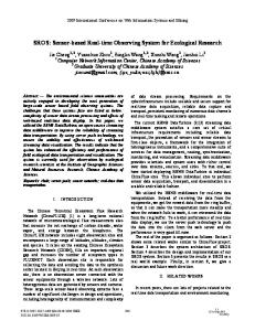
A. Data Aggregation and Analysis The smartphone receives 150 frames/s containing data from three sensors. The app marks each frame with a timestamp before saving data to text file. This is done so that data can be made available offline for algorithm validation and refinement. Algorithms for functional monitoring based on tri-axial accelerometer and gyroscope have been implemented offline in previous work [11][18]. The algorithm calculates static angles for each sensor based on acceleration values and then implements a complementary filter to compensate for the gyroscope drift and outputs the sensor’s angle of tilt with respect to reference axis. Fig. 6 below illustrates lean angle calculation of the sensor on the right leg with respect to the vertical axis. See reference [11] for detailed formulae.
SMARTPHONE APP
We developed an app called ‘Tracker’ using the objectiveC language in the Xcode developer environment for iOS 4.2. TABLE II. MASTER BI-DIRECTIONAL SHARED CHANNEL PARAMETERS Parameter Channel Number Device Number Device Type Transmission Type Channel Frequency Channel Period Scan Timeout
Value 0x03 0x01 0x03 0x03 2520 MHz 3277 (10 Hz) 30 s
TABLE III SLAVE BI-DIRECTIONAL SHARED CHANNEL PARAMETERS Parameter Channel Number Device ID Device Number Device Type Transmission Type Channel Frequency Channel Period
Value 0x01 Unique Device ID between 0x0001-0xFFFE 0x01 0x03 0x03 2520 MHz 3277 (10 Hz)
Figure 4. Left: Flowchart - Master Scan Mode; Right: Flowchart: Slave Discovery Mode
www.redpel.com +9176205933894
Figure 7. Devices comprising the WPAN
Figure 6. a) Acceleration along X-axis b) Acceleration along Y-axis c) Acceleration along Z-axis d) Angular Velocity about Y-axis e) Lean angle calculation of sensor on right leg
To classify static and dynamic activities, the algorithm implements a decision tree. This involves calculating the power spectral density of windowed data. We use the Accelerate Framework to optimally execute vector math and signal processing in our algorithms. We use the AudioToolbox library to provide real time auditory cueing for excessive forward lean alarm. B. Graphical User Interface (GUI) We developed a clean and intuitive GUI on the smartphone to support activity monitoring. On the main view we display the current activity classification and a summary of individual tilts for the chest, left leg and right leg sensors. We also provide options to calibrate (auto-zero) the sensors, scan for new sensors and disconnect detected sensors. V.
[1] [2] [3]
[4]
[5] [6] [7]
[8]
CONCLUSION
In this paper we describe the rational for the design of an activity monitoring system comprised of compact, wearable, low powered, wireless sensors and a smartphone as the central node to collect and analyze sensor data. Key design goals are to support real time 50 Hz data sampling from multiple devices, continuous operation for at least 24 hours, and interconnection to smart communications infrastructure to allow remote data collection and interpretation. The device operation and algorithms will continue to be optimized towards achieving successful event classification with longer periods of operation through clever detection of inactivity. By increasing longevity, the device is expected to have improved monitoring compliance necessary for in-home and community-based adoption. VI.
VII. REFERENCES
ACKNOWLEDGMENT
The authors would like to acknowledge Wallace H. Coulter Translational Research Partnership Awards and The Boston Claude D. Pepper Older Americans Independence Center (OAIC) for partly supporting the work.
[9] [10] [11]
[12] [13] [14] [15] [16] [17] [18]
E. Singer, “The Measured Life,” Technology Review, vol. 114, pp. 3845, 2011. D.K. White, R.C. Wagenaar, and T. Ellis, “Monitoring activity in individuals with Parkinson’s disease: A Validity study.” Journal of Neurological Physical Therapy, vol. 30, pp. 12-21, 2001. D.K. White, R.C. Wagenaar, M.E. Del Olmo, and T. Ellis, “The testretest reliability of 24 hours of activity monitoring in individuals with Parkinson’s disease in home and community,” Neurorehabilitation and Neurological Repair vol. 21, pp. 327-40, 2001. D.K. White, R.C. Wagenaar, T. Ellis, and Tickle-Degnen, “Changes in walking activity and endurance following rehabilitation for individuals with Parkinson’s disease,” Archives of Physical Medicine and Rehabilitation, vol. 90, pp. 43-50, 2009. J.R. Knickman and E.K. Snell, “The 2030 Problem: Caring for Aging Baby Boomers. Health Services Research, vol. 37, pp. 849–884, 2010. F.M. Gloth IIIrd, J. Walston, J. Meyer, and J. Pearson, “Reliability and validity of the Frail elderly functional assessment questionnaire,” Am J Phys Med Rehabil, vol. 74, pp. 45-53, 1995. B. Kopp, A. Kunkel, H. Flor, T. Platz, U. Rose, K. H. Mauritz, K. Gresser, K. L. McCulloch, and E. Taub, “The arm motor ability test: reliability, validity, and sensitivity to change of an instrument for assessing disbilities in activities of daily living,” Arch. Phys. Med. Rehabil, vol. 78, pp. 615-620, 1997. M. N. Nyan, F. E. H. Tay, and M. Z. E. Mah, “Application of motion analysis system in pre-impact fall detection,” J Biomechanics, vol. 41, pp. 2297-2304, 2008. D.W. Esliger, A.V. Rowlands, T.L. Hurst, M. Catt, P. Murray, and R.G. Eston, “Validation of the GENEA Accelerometer,” Medicine & Science in Sports & Exercise, vol. 43, pp. 1085-1093, 2011. IMU 6DOF v4 Sensor Board, SEN-08726, Sparkfun Electronics. Y. Zhang, I. Sapir, S. Markovic, R. C. Wagenaar, and T.D.C. Little, “Continuous functional activity monitoring based on wearable tri-axial accelerometer and gyroscope”, Proc. Workshop on Cognitive Sensor Networks for Pervasive Health (CoSN-PH 2011), Proc. 5th Int ICST Conf on Pervasive Computing Technologies for Healthcare (PervasiveHealth 2011), Dublin, Ireland, 2011. MSP430F2619 Datasheet, Doc. SLAS541I-JUNE2007-REVISED JULY 2011, Texas Instruments. ADXL345: 3-Axis, ±2 g/±8 g/±16 g Digital Accelerometer Data Sheet (Rev C, 05/2011), Analog Devices. ITG3200 Datasheet, Doc. PS-ITG-3200A-00-01.4, InvenSense Inc. www.thisisant.com AP2 RF Transceiver Module Datasheet, Doc. D00001266, Rev 1.7, ANT. AT3 RF Transceiver Module Datasheet, Doc. D00000975, Rev 2.3, ANT Wagenaar, R.C., Sapir, I., Zhang, Y., Markovic, S., Vaina, L.M., & Little, T.D.C. (2011). Continuous monitoring of functional activities in the home and community setting. Proceedings 33rd Annual International Conference of the IEEE Engineering in Medicine and Biology Society (EMBC '11), Boston
www.redpel.com +9176205933895